Purdue Medium Voltage DC Testbed
Purdue’s Medium Voltage (representative) Testbed1 is a voltage and power scaled dc power system with strong architectural similarities to power systems being investigated for future Navy ships. As with any power distribution architecture, there are numerous design considerations which need to be addressed. In the case of medium voltage dc systems, these considerations include the effective paralleling of dc sources, stability in the presence of numerous constant power loads, fault-protection, and grounding. A one-line diagram of the system appears below.
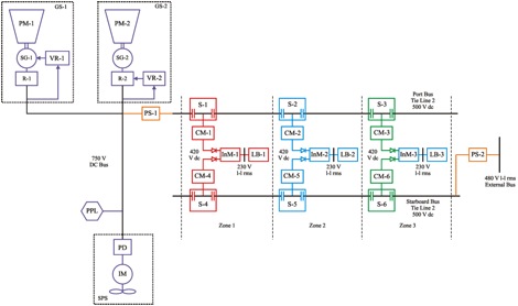
Medium Voltage DC Testbed One-Line Diagram
The system includes two generation systems (GS-1 and GS-2), a ship propulsion system (SPS), a pulsed power load (PPL), as well as lower-power zonal dc distribution system. Generation system GS-1 includes a 59 kW wound rotor synchronous machine designated SG-1 connected to a passive rectifier R-1. Voltage regulator VR-1 adjusts the field so as to regulate the output voltage. Generation system GS-2 is based on an 11 kW permanent magnet synchronous machine denoted SG-2, which is connected to the system via an inverter. The voltage regulator VR-2 controls the inverter so as to regulate the output voltage. Both VR-1 and VR-2 have provisions for load sharing. The nominal output voltage of GS-1 and GS-2 is 750 V. Both generators are driven by four-quadrant dynamometers which will emulate prime movers. These are labeled PM-1 and PM-2 in the figure above.
The ship propulsion system SPS-1 is the dominant load at 37 kW peak power. The second largest load is the pulsed power load PPL, which emulates a rail gun system and draws a peak power of 18 kW. The power supply PS-1 is utilized to step down the 750 V dc to 500 V dc and to distribute the power to the dc zonal systems via the port-side dc distribution bus. Power supply PS-2 provides power for the dc zonal systems via the star-board side dc distribution bus. It is intended to represent the effects of additional generation systems (which are physically not present) supporting the starboard distribution bus. PS-2 receives a three-phase 480 Vll-rms power from the utility grid. Using a line-commutated rectifier and the appropriate control, PS-2 converts the ac power into 500 V dc.
 |
 |
 |
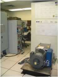 |
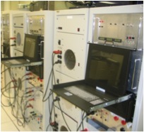
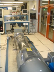
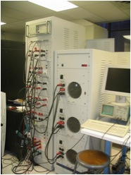
Medium Voltage DC Testbed Hardware
In the dc zonal system, six converter modules CM-1 through CM-6 are utilized to step the 500 V dc down to 420 V dc. These converter modules provide protection to the port and starboard side distribution bus in the case of zonal faults. There are two CMs in each zone. The two CMs operate in parallel to provide power to the inverter module (InM). In the case of a fault to one of the converter module or the distribution bus, the other converter module is able to pick up the load and continue services to the inverter module (InM)-load bank (LB) system. The InMs are utilized to convert the 420 V dc into a three-phase 230 Vll-rms ac, which is the form required by the 5 kW load banks (LB).
Research at Purdue is focused on stability of the interconnected system, generator design, and grounding issues.
1 M. Bash, R.R. Chan, J. Crider, C. Harianto, J. Lian, J. Neely, S.D. Pekarek, S.D. Sudhoff, N. Vaks, “A Medium Voltage DC Testbed for Ship Power System Research,” IEEE Electric Ship Technologies Symposium, Baltimore, MD, April 20-22, 2009.