Burner (Combustor)
The burner receives flow from the compressor, separates some of the flow, mixes it with fuel and ignites it, remixes the flow, and delivers it to the turbine.
| The burner's life is not an easy one. In order to assure ignition, the mixture of fuel and air should be stoichiometric, and not moving very fast. However, far more air passes through the engine than is required for complete combustion of the fuel. Hence, the burner starts by separating out a small portion of the air and decelerates it for combustion in the ``primary zone''. The gases leaving this region are far too hot to be tolerated by current technology turbines. For this reason, the remaining air (sometimes called dilution air) is then mixed with the hot gases from the primary zone to produce a nearly uniform temperature stream entering the turbine. | |
 |
There are several varieties of burner. The earliest was the multiple can burner. This operated by totally separating the flow into eight or so cans, each of which contained a flame tube and also dealt with the flow around it. |
 |
The first major Improvement on this design led to the can-annular burner, which retained the multiple flame tubes of the previous type, but allowed the outer air to flow free around all the flame tubes. Can-annular designs have less efficient combustion, but because of their modular design they are easier to repair or replace. |
 |
Modern combustion chambers are totally annular. The flame tube makes a ring around the entire engine. This results in much higher combustion efficiency- nearly all of the fuel is burned completely. This reduces noxious emissions. Such burners are, however, more difficult to service. |
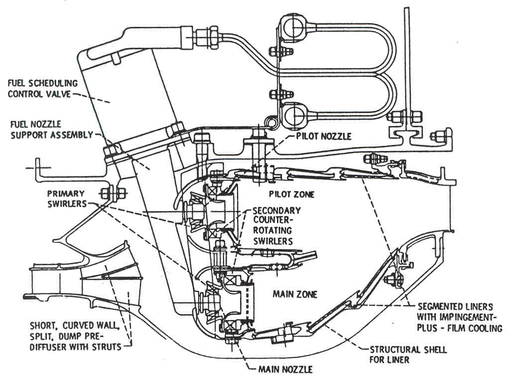
| The next step in burners may be a double-annular chamber, in which there are two concentric flame tubes. Dual annular designs are being pursued in order to lower emissions. By using two rows of burners, the dual-annular combustor can use just a single row during low power (idle, descent) conditions, while both sets are lit under high power (takeoff, climbout) conditions. | |
| Here is a large schematic of a combustion chamber |
 |
![]() Compressor : Turbine
Compressor : Turbine ![]()