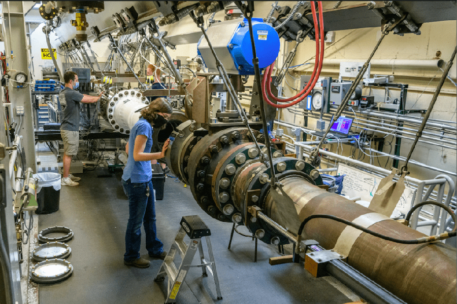
Hypersonics Facilities
Learn MorePurdue Hypersonics Partners
Learn MoreGuidance, Navigation, Control
Learn MoreSystem Engineering, Integration, Command and Control
Learn MoreAerodynamics/Aerothermal Effects
Learn MoreHigh Temperature Materials and Manufacturing
Learn MorePropulsion and Diagnostics
Learn MoreSensors and Atmospheric Effects
Learn MoreEnergetic Materials
Learn MoreOverview: Heeding the Call
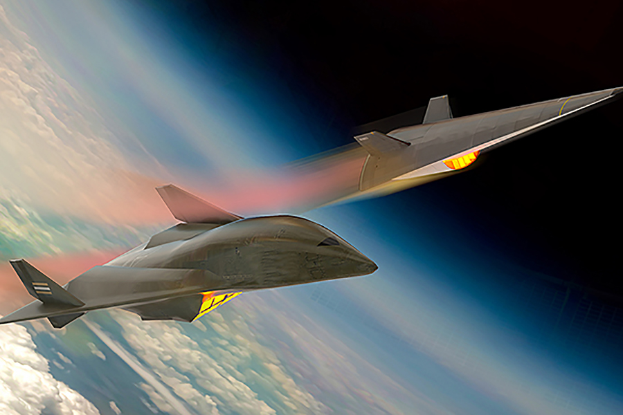
Today’s geopolitical environment is driving intense focus on developing hypersonic systems that meet our nation’s defense and security needs, both now and for the foreseeable future. Given this reality, our nation needs to cultivate the best ideas and harvest resulting innovations from universities to realize the advanced capabilities of these systems.
There is wide agreement on the need for multidisciplinary research that converges state-of-the-art science in aerodynamics, materials, control systems, etc., to create robust hypersonic systems. Universities must collaborate with government and industry to craft multidisciplinary research leading to viable technologies that can be manufactured at scale.
Purdue’s large, interdisciplinary team of hypersonic research experts brings great depth and breadth of experience in basic and applied research for feasibility determination and design of strong, next-generation hypersonic systems. Purdue researchers are advancing experimental methods as well as computational tools in aerodynamics, materials, propulsion and control/trajectories disciplines, systems-level modeling, energetics and rapid verification and validation to reduce the risks involved in acquisition, production and fielding of hypersonic systems.
Research at Purdue that complements the University’s hypersonics work is equally critical to meeting the nation’s requirements. Purdue excels at systems-engineering research, and has demonstrated techniques for systematic integration of multiple technologies amid uncertainty. This advantage is key in achieving rapid innovation and transition to operational use.
Our faculty and students — partnered with their colleagues from universities across the nation — are a powerful “brain trust” for the national teams. We are positioned to solve the most challenging problems through full-scale lab flight tests. Learning from flight must be augmented with simulation models that are seamlessly tied to HWIL in model-based fashion.
Universities also must drive continuous learning. We must unify the science and engineering base to support warfighters and operators of civil systems. Purdue has a comprehensive plan for next-generation workforce (NGW) development from high school through PhD programs and beyond. Key components include internships that seamlessly connect campus-based research with relevant test facilities and mission-application expertise in government labs and industry.
This cycle of continuous refinement of knowledge will lead to quicker transition of technical solutions while simultaneously producing graduates with in-the-field experience that makes them “system-aware” from their first day on the job.
NGW is underpinned by our model-based environment that infuses the new content into the curriculum, especially in ways that reinforce the multidisciplinary, systems-oriented approach that is so critical to our success. Purdue will leverage its extensive partnerships with national/Department of Defense labs and industry in realizing this NGW vision.
Purdue University leadership is committed, at the highest level, to serving our country’s needs in national security and defense at the necessary security levels — and with the speed the nation requires. Purdue is resolute in its determination to answer the nation’s call in hypersonic systems development and fielding. To this end, we encourage prospective partners to contact Dan DeLaurentis and join us in our pursuit of enabling science and technology to give the U.S. defense community a commanding technological advantage in this field.