RTD Temperature Dependence

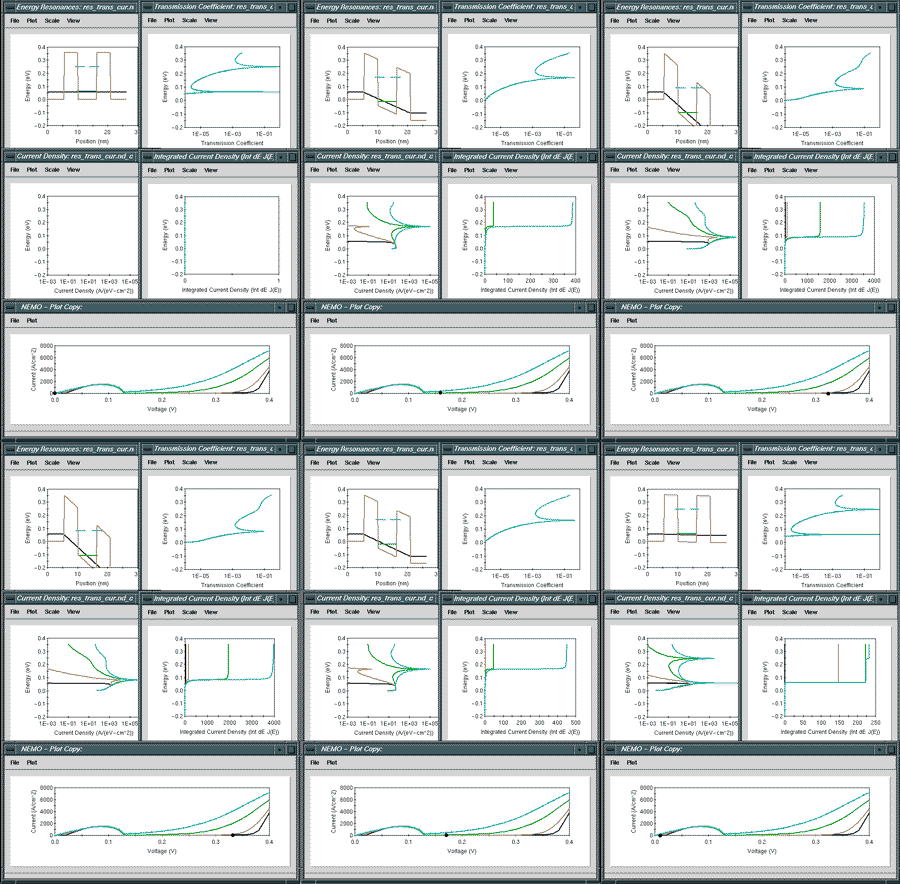
The figure on the left shows five panels: Top Left: Conduction band edge with resonances.Top Right: Transmission coefficient as a function of energy.Middle left: Current Density as a function of energy.Middle right: Running integral of the current density.Bottom: Current voltage characteristic
The electron reservoir or electron sea in the emitter determines the injection of electrons into the central device. Only at very low temperatures is the Fermi sea actually "flat" in the figurative sense that there are "no" electrons above the Fermi level. At higher temperatures electrons are thermally excited according to a Fermi-Dirac distribution.
The effect of the electron reservoir temperature of 4.2 (black), 77 (brown), 200 (green), and 300 (turquoise) degrees Kelvin are depicted in the animation. Notice that the transmission coefficient does not change (we have not changed the lattice temperature in this simulation just the electron temperature). The current density clearly shows the thermal electron excitation trail. For higher temperatures more and more highly energetic electrons make it through the structure. The so-called valley current between the main resonance peak and the second turn-on is raised significantly with an increase in electron temperature.
The "running integral" of the current density shows "where" the current is flowing in energy space by the relative height of the step functions. Two steps can be observed for the the high temperature (300K) curve for voltages below 0.1V - below the main peak. That means that there is significant current flowing through the second resonance on the main peak at 0.1V.
The simulations shown here only illustrate the basic operation of an RTD including some temperature effects. Other modeling caveats such as the treatment of the contacts, charging effects and bandstructure effects are not included here.
