Contact Treatment Comparisons Different Open Boundary Conditions
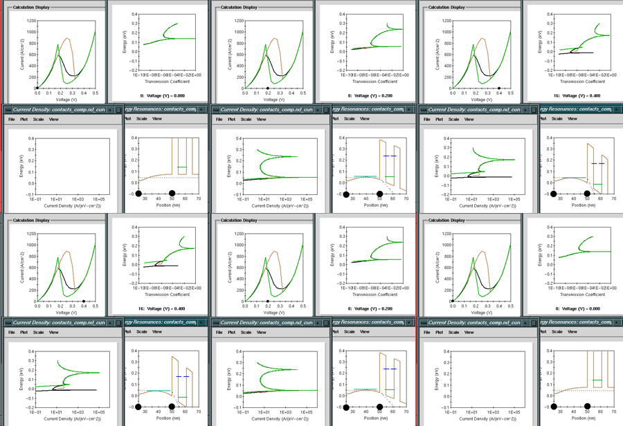
The figure on below shows four panels: Top left: Current voltage characteristicTop right: Transmission coeffcient.Bottom left: Current density.Bottom right: Conduction band edge with resonances

To enable current flow through the structure one has to apply open boundary condistions to the system. For a flat band (no applied voltage) one can compute the incoming and outgoing waves analytically. This analytical solution can be attached to the simulation domain which contains spatially varying potentials. The two "traditional" ways to attach flat band boundary conditions are either to attach them to the very end of the modeled device (green line, left big dot in the bottom right figure) or just to the left and the right of the barriers (brown line, right big dot in the bottom right figure). Attaching the open system boundary conditions immediately outside the barriers eliminates any effects of the emitter quasi-bound states such as charging and resonance enhancements. The emitter quasi-bound states effectively raises the emitter conduction band edge to a higher energy. Without that raise in energy the current turns off at a too high of a voltage.
Attaching the boundary conditions to the very end of the device does not include the filling of the emitter quasi-bound states with electrons and cuts off the current at the top of the emitter band profile hump. In this case the current will be shut off too low in voltage.
A breakthrough in RTD modeling was achieved when open boundary conditions that include the emitter qusi-bound states on equal footing with the continuum states. For more information please see formal publications such as [10,12]. The new boundary conditions include the filling of the emitter quasi-bound states due to scattering and the injection of carriers out of these states into the central device. These boundary conditions have been the key to quantitative resonant tunneling diode modeling, together with charging and bandstructure effects.
The simulations shown here only illustrate the basic operation of an RTD. Effects such as temperature dependence, charging effects and bandstructure effects are not included here.
