Featured Research
Aerocapture Guidance, Navigation, and Control
Rohan Deshmukh
Aerocapture, as shown below, is a promising propellant-saving orbital insertion technique for planetary destinations with an atmosphere. A technology that enables robust aerocapture performance is the guidance algorithm, which autonomously commands the vehicle’s flight control during atmospheric flight to achieve the desired orbit at exit in the presence of significant atmospheric dispersions. Such flight control techniques envisioned for aerocapture vehicles include bank angle modulation (BAM), drag modulation (DM), and direct force control (DFC). Despite the existence of these different techniques, there does not exist a unifying architecture that allows for critical guidance trade studies to be conducted in preparation for future flight projects. Such trade studies are needed to ascertain what vehicle geometries (slender vs blunt body, rigid vs deployable systems), flight control (BAM vs DFC vs DM), and actuator mechanisms (propulsive vs non-propulsive) are needed to best achieve mission success at each planetary destination. The research presented here addresses this limitation through the formulation of a modular aerocapture guidance architecture.
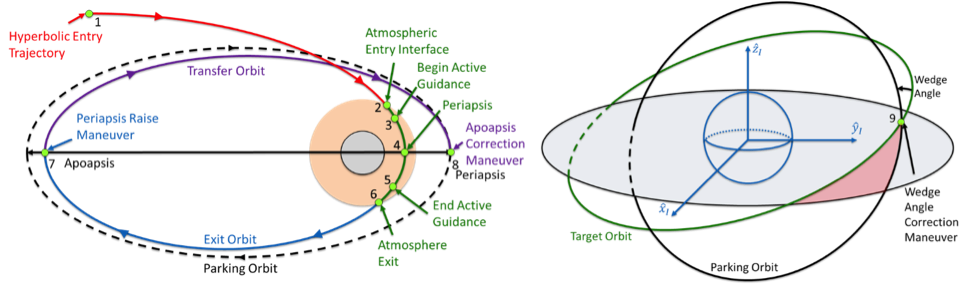
Figure 1. Aerocapture orbit insertion technique. Aerocapture utilizes the planetary atmosphere to capture a hyperbolic entry trajectory to a targeted elliptical orbit. Propulsive burns are used to raise periapsis out of the atmosphere and correct for apoapsis and orbit plane targeting errors
A visualization of the modular guidance architecture being developed is shown below. The design enables the rapid assessment of aerocapture trajectories for a variety of vehicle geometries, flight actuators, flight control methodologies at different planetary destinations.
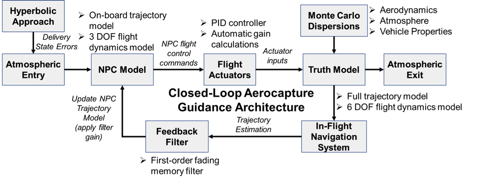
Figure 2. Modular aerocapture guidance architecture flowchart.
Because aerocapture trajectories are influenced by the vehicle’s aerodynamics, an analytical aerodynamics model is formulated using Newtonian aerodynamics. This methodology allows for the hypersonic aerodynamics of the vehicle and aerosurface actuators to be approximated as a function of the flow-field (i.e. Mach number), vehicle geometry (i.e. sphere-cone, biconic), and aerodynamic attitude (i.e. angle of attack, side-slip angle). The figures below show some sample applications of the analytical aerodynamics model to lifting and ballistic vehicles.

Figure 3. Sample analytical aerodynamics model for a 70 deg sphere-cone aeroshell as function of angle of attack (alpha) and side-slip angle (beta). Analytical relations help facilitate the derivation of DFC flight control laws.
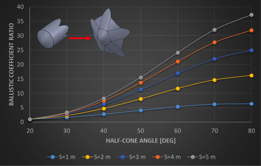
Figure 4. Ballistic Coefficient Ratio vs Cone
Angle deflection for different aeroshell reference lengths (S). A
continuously-varying drag modulation flight control system can achieve large ratios
through an increase in cone angle and reference length.
To achieve trajectories that minimize orbit insertion ΔV, optimal control theory is applied to ascertain the flight control law for each flight control technique. The aerodynamics model facilitates the derivation of “bang-bang” optimal control laws for each flight control technique. This unified control structure enables the application of a numerical predictor-corrector (NPC) guidance algorithm. The NPC commands are dynamically achieved through actuation of the flight control surfaces in a 6 DOF environment. The gains applied to the actuator inputs are automatically computed using a PID controller. The figure below illustrates this process for bank angle modulation.
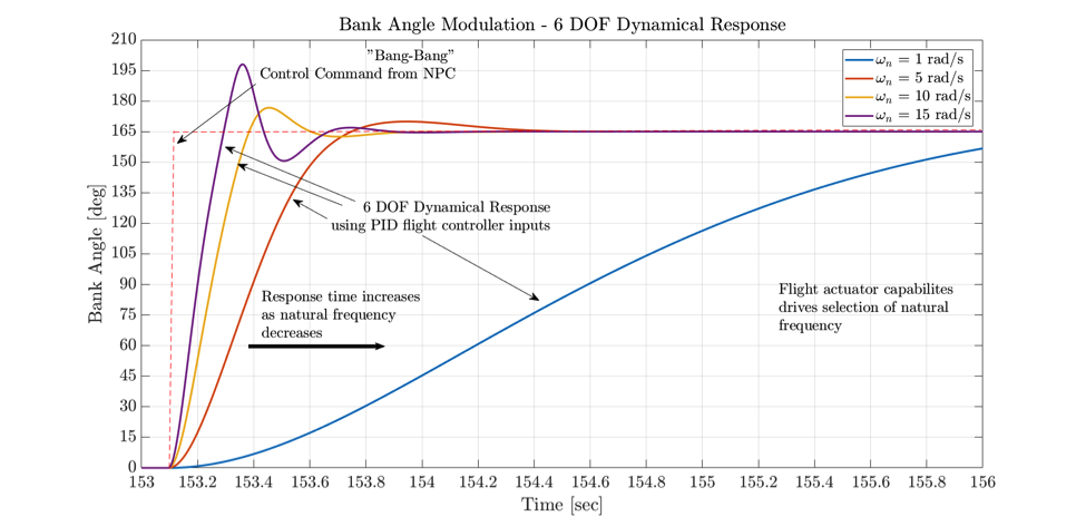
Figure 5. Sample 6 DOF non-linear dynamical response for a NPC bank angle command using PID controller with different natural frequencies. The PID controller utilizes a linear approximation to the non-linear rotational equations of motion for automatic gain computation. The gains are utilized for computing pitch, yaw, and roll RCS thruster inputs
To mitigate trajectory dispersions, such as density dispersions as shown below, the guidance is made closed-loop through the integration of a trajectory estimator. The estimator utilizes on-board navigation measurements with a feedback filter to determine update gains utilized by the NPC algorithm. Monte Carlo simulations using a variety of trajectory dispersions are conducted to assess their cumulative effect on the aerocapture orbit insertion performance.

Figure 6. Sample Mars atmospheric density profiles simulated using MarsGRAM 2010. Density perturbations can cause significant errors in aerocapture trajectory. A feedback filter can help to improve the on-board knowledge of the atmosphere given sensed data measurements.
A sample BAM Mars aerocapture simulation is presented to illustrate the use of the architecture. The video depicts a Mars Science Laboratory-derived aeroshell targeting a 400 km circular orbit at 30° inclination as simulated in a 6 DOF nominal environment. The NPC guidance algorithm actively computes each guidance cycle both the bank angle magnitude needed to minimize the orbit insertion ΔV and the bank angle sign to manage the orbit plane.