Aerospace Thermal Management
Avionics Cooling
Cooling of avionics onboard modern military and commercial aircraft is achieved inside a rectangular avionics enclosure that serves the multiple purposes of mechanical mounting of circuit boards and electrical interconnect, in addition to the cooling. An avionics enclosure contains several closely packed modules that contain the circuit boards. In the majority of today’s avionics, each module houses two circuit boards mounted back-to-back against a thermally conducting substrate. The substrate routes the heat dissipated by the circuit boards to the top and bottom heat exchange walls of the avionics enclosure, where the heat is rejected to air bled directly from the engine’s compressor or bypassed from the engine’s fan.
Because of the ‘long’ thermal path from device to cooling air, cooling rate of a conventional 5.38 in x 6.41 in x 0.59 in edge air-cooled module is limited to no more than 40 W. However, by the early 1990’s, device and packaging developments in military aircraft resulted in substantial increases in heat dissipation at the module level. Edge air cooling was replaced by a new generation of indirect liquid cooling modules, where the conducting substrate was replaced by a hollowed, liquid-cooled metallic frame. Using polyalphaolafin (PAO) as single-phase liquid coolant, the heat dissipation capability per module increased to about 200 W.
Open cavity Module C1 - Two effective means to improving the cooling performance of an avionics module are to allow the coolant to make direct contact with the device, and to undergo phase change (boiling). Our team developed a clamshell-type module, Module C1, which features an open inner cavity inside which two circuit boards are attached to the module’s inner walls. Dielectric coolant FC-72 is supplied into the cavity and allowed to flow undirected at very low speed before exiting the module to an external conditioning flow loop. We demonstrated this module could dissipate over 820 W, four times the cooling rate of the PAO module.
Micro-channel Module C2 - Our team later incorporated two-phase micro-channel cooling to further enhance the thermal performance of their earlier clamshell module. The newer Module C2 houses two circuit boards that are separated by a flow distribution plate. The coolant passes through parallel narrow micro-channels formed between the distribution plate and surfaces of the devices. Capitalizing upon the merits of micro-channel flow boiling, Module C2 was demonstrated to dissipate over 3000 W using FC-72, corresponding to a mild flow rate of 0.051 kg/s (0.50 gpm), 40.5°C subcooling, and a pressure drop of only 2.8 kPa (0.41 psi).
Jet impingement/micro-channel Module C3 - Another important advancement in two-phase avionics cooling is our team’s Module C3. This module is double-pitched, meaning it is twice the thickness of Module C1 or Module C2, ensuring electrical and fluid connection compatibility with standard avionics enclosures. Module C3 employs direct jet-impingement of FC-72 upon the device surface, and fluid from the impingement zone is expelled though two micro-channels formed between the flow distribution plate and device surface. Module-C3’s performance exceeded 12 kW, 60 times that of the PAO module. Device heat fluxes as high as 255 W/cm2 were achieved within this module.
Following are important lessons learned from the development the three clamshell modules concerning enhancement of avionics cooling:
- Replacing air cooling and indirect liquid cooling with direct-immersion cooling.
- Capitalizing upon the merits of phase change (boiling).
- Enhancing cooling performance through more effective liquid interaction with the surface using such configurations as micro-channel flow and jet impingement.
- Greatly increasing coolant subcooling at the module’s inlet to (i) reduce vapor production within the module, (ii) increase critical heat flux (CHF), and (iii) condense bubbles before they exit the module. Bubble condensation offers the benefits of both simplifying coolant conditioning external to the module, by employing essentially a single-phase liquid loop, and reducing coolant flow sensitivity to large body forces encountered in military aircraft.
Cryogenics Thermal Management
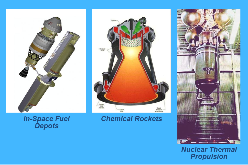
Cryogenic fluids are employed in many industries, and play crucial roles in space applications, including liquid helium chill down of Earth-orbiting telescopes and satellites, and liquid hydrogen rocket fuel transfer system prechill and propellant transfer for thrust. Due to the ultra-low boiling point of cryogens, phase change is inevitable in these systems, which leads to complex two-phase flow boiling behavior. Our studies are focused on hydrogen flows in nuclear thermal propulsion (NTP) systems, which promise appreciable enhancement in performance and decrease in transit time for future manned missions to Mars and beyond when compared to standard chemical propulsion systems. In this application, the hydrogen is stored in the propellant tank in subcooled liquid state, but begins to flash and boil while being transferred through the feed system before entering the reactor in superheated vapor phase. It is within the feed system that accurate knowledge of local two-phase pressure drop and heat transfer coefficient is desired.
Another goal of our study is to develop accurate predictive tools for cryogenic fluids to be incorporated into NASA’s multi-node codes to enable design and sizing of NTP propellant feedsystem. This work is also expected to extend beyond NPT systems, by providing design tools for LOX/LCH4 ascent and descent stage feedlines, LOX/LH2 transfer lines for in-space fuel depot, and LHe transfer lines that cool space experiments.
Spacecraft Hybrid Thermal Control System
As space missions increase in scope, size, complexity and duration, so do both power and heat dissipation demands. This is particularly the case for future missions to Mars and asteroids. Paramount to the success of these missions is the ability to reduce size and weight, including those of thermal management sub-systems. One means to achieving this goal is to transition from single-phase to two-phase thermal management. By capitalizing upon the merits of latent and sensible heat rather than sensible heat alone, two-phase systems can yield orders of magnitude enhancements in evaporation and condensation heat transfer coefficients compared to single-phase systems. These improvements are evident from recent NASA workshops that culminated in critical recommendations concerning implementation of flow boiling and condensation in a variety of space sub-systems such as Rankine cycle power conversion, cabin thermal management, and advanced life support.
The Thermal Control System (TCS) plays a vital role in life support in space vehicles and planetary bases. This system is responsible for controlling the temperature and humidity of the environment. With increased duration and complexity, future space missions will demand TCS architectures with significantly reduced power input, mass and volume. The TCS must tackle three primary tasks, heat acquisition, heat transport and heat rejection. Heat acquisition components acquire energy from a heat-producing source and transfer it into the TCS. Heat transport components move the energy from the heat acquisition source to heat rejection hardware. The heat rejection components reject the heat from the TCS to the outside environment.
The TCS must tackle heat removal from a variety of sources while maintaining all individual spacecraft components within their required limits. There are several sources of heat input, including solar radiation, albedo, radiation from planets, and heat generation from internal equipment and crew. Both passive and active TCS architectures have been used in the past. The advantage of passive TCS is absence of moving parts or reliance on electrical power input, however passive systems are intended for low heat loads. Crewed missions involve high power input and demand operation within a narrow temperature range with a quick response time, which require an active TCS that includes pumps, heaters, and moving parts with electrical power input.
Active systems used in both the retired Space Shuttles and the International Space Station (ISS) rely entirely on single-phase operation. NASA studies have shown remarkable benefits to transitioning from single-phase to two-phase active systems, especially with the projected high increases in heat load. A key reason behind difficulty using active two-phase TCS is limited understanding of two-phase flow behavior in reduced gravity.
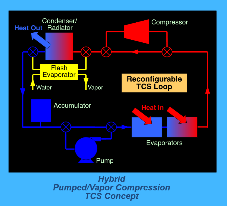
One source of difficulty in TCS design is the need to operate in both cold and warm environments, which complicates heat rejection from the spacecraft. For cold environments common to most crewed missions, the heat is rejected by radiation to the colder environment. On the other hand, warmer environments (e.g., Lunar missions away from the polar regions) require a heat pump system to raise the coolant temperature above ambient. To accommodate both cold and warm environments, a ‘hybrid’ active TCS architecture is being investigated by our team, which can be reconfigured during the space mission, to respond to, not only ambient temperature, but varying heat input as well.
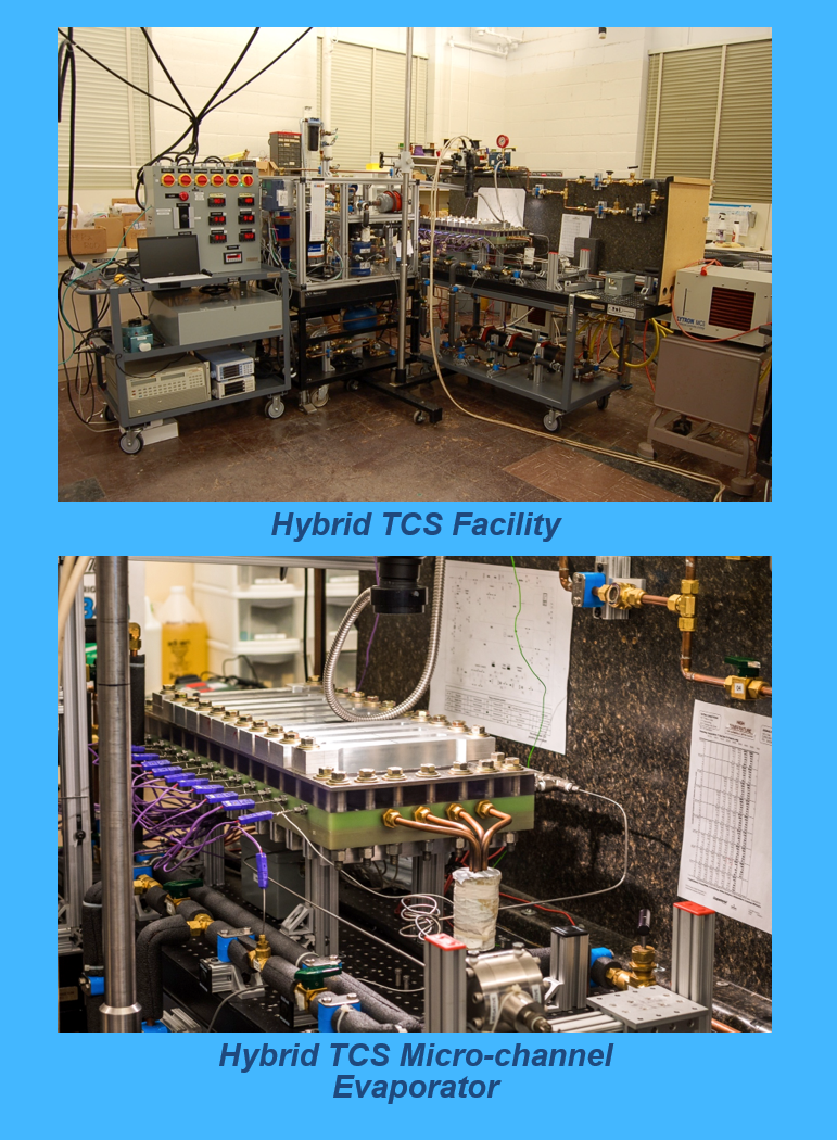
The hybrid TCS is essentially a closed loop cooling system modified with bypass heat pump and flash evaporation/sublimation sub-systems. This system can be reconfigured upon demand by operating either as a pumped two-phase loop or vapor compression loop. For cold environments, the heat pump subsystem is bypassed and the loop consists of an accumulator, pump, evaporators (cold plates), and condenser/radiator. The same loop can operate either in single-phase mode for low power input or two-phase mode for high power input. For warm environments, the coolant vapor exiting the evaporators is routed through a compressor to raise its temperature above ambient and facilitate heat rejection through the condenser. The liquid exiting the condenser is passed through an expansion device to reduce its temperature before entering the evaporators.
Rocket Engine Cooling
The walls of thrust chambers in modern liquid rocket engines encounter very high pressures and temperatures. In hydrogen/oxygen liquid rocket engines, the walls are cooled by hydrogen flowing at high flow rate through rectangular micro-channels. Wall cooling effectiveness is of paramount importance to the thrust chamber’s life, which can be nearly doubled if wall temperature is reduced by 50-100°C.
High cooling performance can be achieved by using a large number of closely spaced thin walls, provided flow in the channels is not severely restricted. A high channel height-to-width ratio both enables maximum utilization of the wall’s fin effect and helps prevent high pressure drop in the cooling channels.
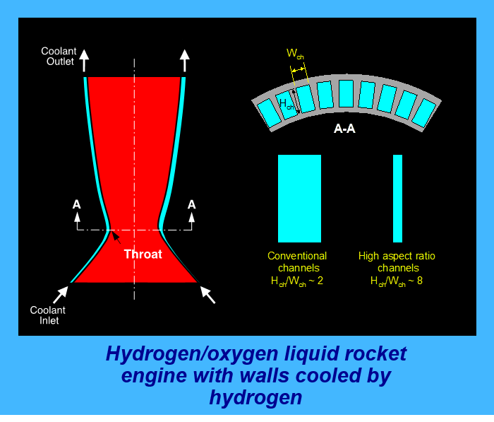
Depending on type of coolant and operating conditions of the rocket engine, flow boiling may or may not be desired. Flow boiling does offer the advantage of greatly enhancing cooling performance and reducing wall temperature. However, critical heat flux (CHF) inside the cooling channel is a primary concern and must be ascertained and prevented. Flow boiling CHF in this application is complicated by the channel’s rectangular shape, high aspect ratio and, most importantly, curvature.
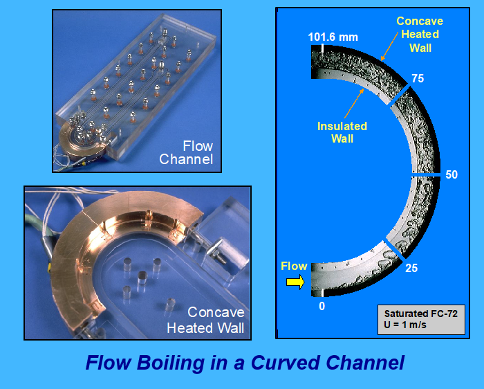
Curvature is known to enhance flow-boiling CHF from concave heated walls. Our team performed photomicrographic studies of vapor coalescence along the concave heated wall of a rectangular channel. These experiments showed centrifugal force pulls vapor inwards (away from the heated wall) and push liquid outwards (towards the heated wall), which serves to prevent vapor blanketing especially near the channel inlet. Farther downstream, vapor is removed from the concave wall, fragmented, and distributed throughout the cooler bulk flow, where it is better able to utilize the bulk subcooling. CHF is enhanced by up to 60% for a centrifugal force equivalent to 315 times Earth gravity.
High Mach Propulsion
Supersonic gas turbine engines pose unique thermal management challenges not encountered in subsonic engines. In both cases, compressor bleed air is used to cool various downstream engine components such as turbine blades and afterburner walls. In subsonic engines, compressor bleed air is cool enough to be used directly for downstream cooling purposes. However, in supersonic engines, compressor bleed air temperature is quite high and therefore a heat exchanger is needed to precool the air before it can effectively cool the downstream engine components.
Compressor bleed air can be cooled by rejecting heat to either engine fan’s bypass air or fuel. In some cases, depending on engine cycle requirements and thermal management architecture, using fuel as heat sink may allow a more compact and lightweight heat exchanger design than using air.
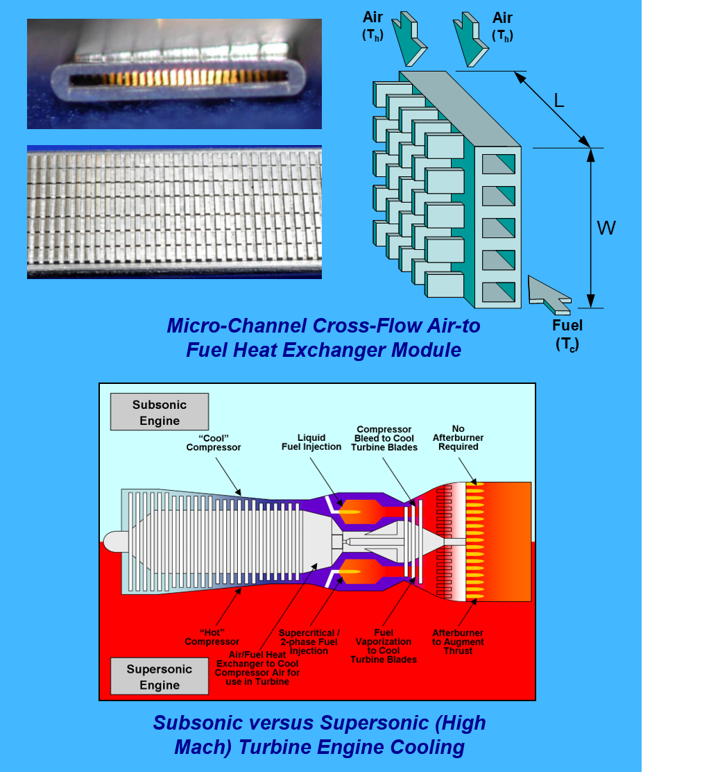
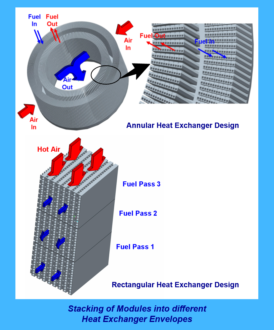
Our team recently developed an air-fuel heat exchanger that is more compact, lightweight and thermally effective than current designs. The new heat exchanger is comprised of many small modules that can be integrated in different ways to suit a variety of engine envelopes. Within each module, fuel is routed through a series of parallel mini-channels formed in a thin monolithic metallic structure. Aside from highly compact and lightweight design, these modules greatly increase both heat transfer area to volume ratio and fuel-side heat transfer coefficient. The module design also enhances heat transfer on the airside with the aid of short rectangular fins. The fins are formed in rows and aligned with the airflow but perpendicular to the direction of fuel flow. The fins enhance airside heat transfer by greatly increasing heat transfer area. More importantly, by using a series of short fins as opposed to continuous fins, they produce large heat transfer coefficients by capitalizing on thin leading edges of multiple airside boundary layers.
Another key advantage of the module design is allowing the air-fuel heat exchanger to be configured in variety of design envelopes, such as annular or rectangular, depending on volume, weight or packaging constraints set by the engine manufacturer.