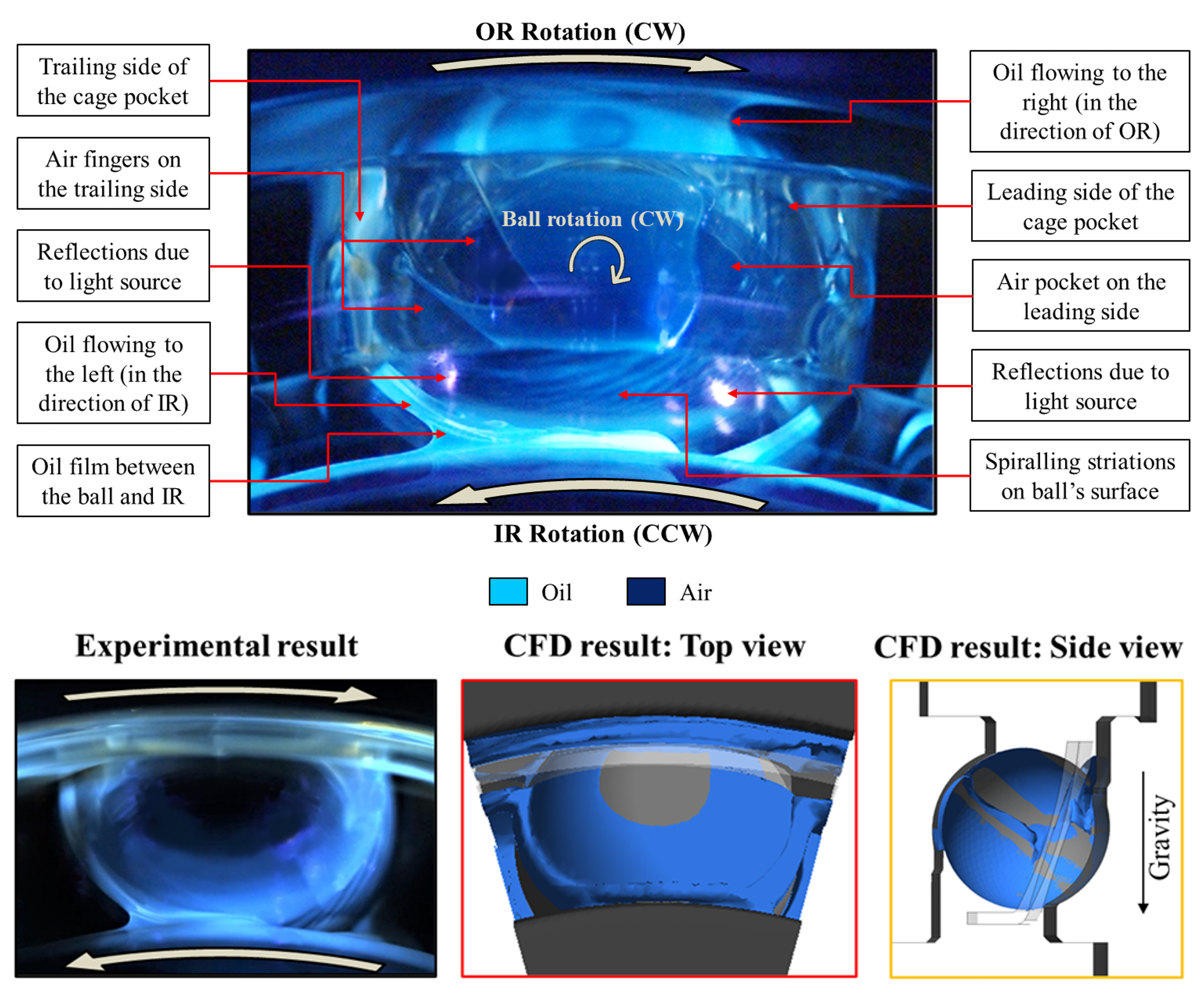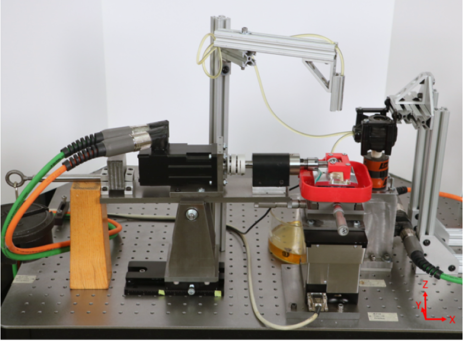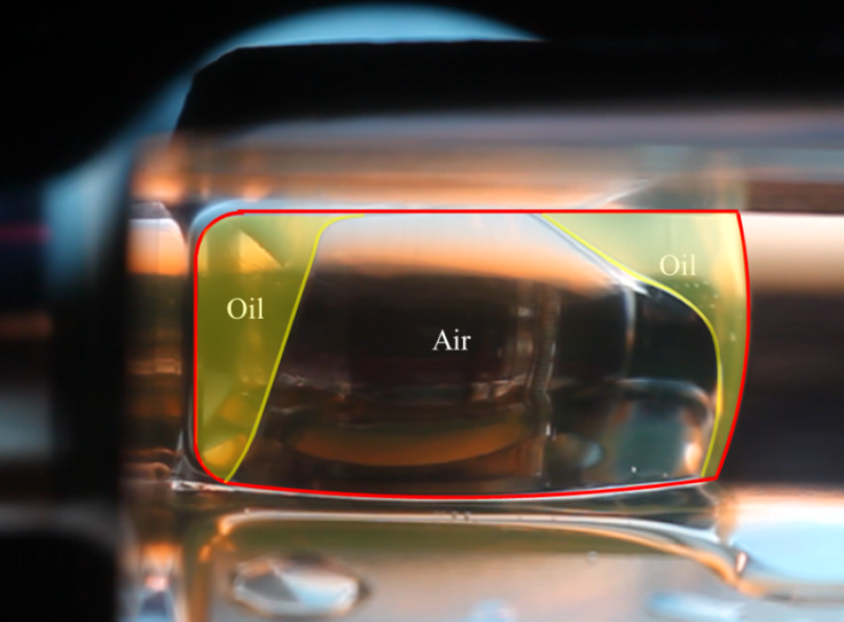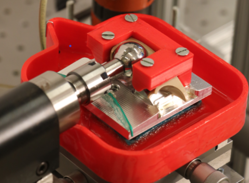

The Counter Rotating Angular Contact ball bearing Test Rig (CRACTR) enables simultaneous rotation of the inner and outer raceways while the cage remains stationary, facilitating the visualization of oil flow in the cage's reference frame. The test bearing's inner race is affixed to a through-hardened steel shaft connected to the upper servo motor, while the outer race is mounted on a shaft/housing assembly serving as both mechanical support and an oil reservoir, linked to the lower servo motor via a spline coupling allowing axial displacement under load. Axial load application is achieved through a lever arm and dead weight system.
The test rig featured proximity probes and load cells to measure 3D cage whirl motion and ball-cage contact forces for an angular contact ball bearing (ACBB) under varying loads and speeds. It was also equipped with a Photron high-speed camera for visualizing motion of aerated bubbles using the innovative Bubble Image Velocimetry (BIV) technique. The rig was also utilized to investigate the influence of operational parameters on oil-air striation patterns and analyze in-situ lubricant distribution within different ACBB cage configurations.
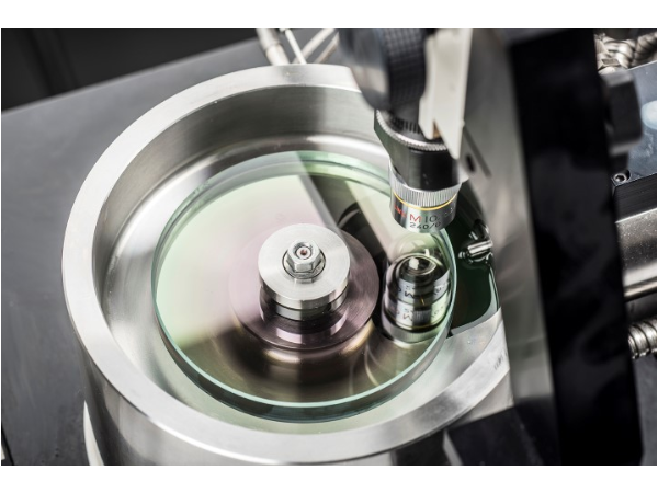
The Bearing Cage Friction Test Rig (BCFTR) was designed and developed to directly measure the friction between the cage and rollers of a variety of ball bearings. The rig features a high precision ATI MINI 40 load cell that measures forces and torques about the X Y and Z axes. The load cell is mounted onto manually controlled X and Y stages that allow for positioning and loading of the ball in the cage. Results from the load cell are used to determine the friction coefficient of the ball - cage contact. The ball is driven by a servo motor and can roll on a spinning glass disc. The disc is also controlled by a servo motor, allowing the rig to simulate a variety of slide to roll ratios. The ball to cage contact region is drip lubricated from oil tank above. Optical measurements of film thickness can be taken through the glass disc to further characterize the state of lubrication in the system.
Bruker UMT Tribolab Pin on Disk (POD) test rig can be used for fretting wear, sliding wear, and friction measurements of different configurations such as ball-on-flat, flat-on-flat, and cylinder-on-flat. Several dual-axis force sensors are available to measure the friction force and the normal force simultaneously. The force sensors can measure a load in the range of 0.5–200 N. There is a reciprocating linear drive with an adjustable stroke length ranging from 30 µm to 25 mm with a frequency of up to 60 Hz for room and high temperature tests. An ultra-high temperature chamber allows testing up to 1000 °C during the process with a controller resolution of 0.1 °C. There is another rotational drive for performing sliding wear test at room temperature.
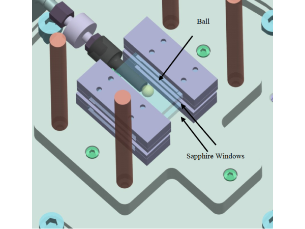
A modular fretting test rig is designed and developed to measure friction and wear for various contact geometries. The test rig is mounted on a machine base and operated using a computer equipped with a data acquisition card and the LabView virtual instrument software. The actuator used to reciprocate the various contact configurations and can operate from 0 to 1000 Hz and achieve a peak to peak displacement of 250 µm. A tension–compression load cell with a 222 N capacity is used to measure the frictional force. A position sensor is used to measure the displacement of the fretting contact. Different configurations are designed including: crossed cylinder, ball on flat and flat on flat. A microscope equipped with a high speed camera can be used to observe the fretting contact of the ball on flat configuration. Both partial slip and gross slip regimes in fretting wear can be obtained using this test rig.
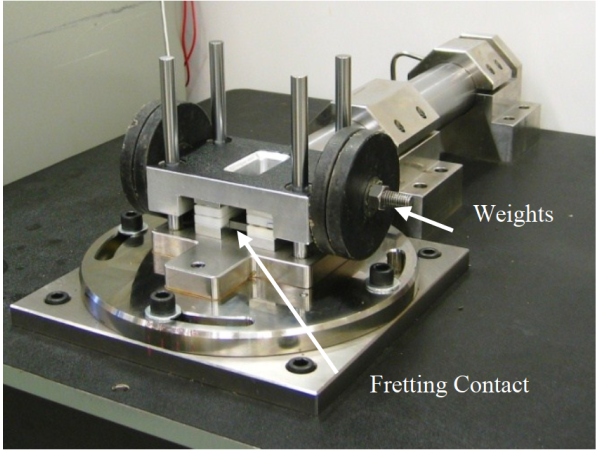
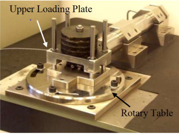
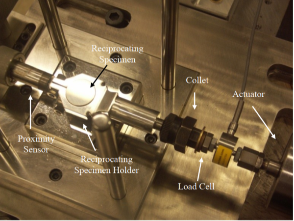
Gas turbines undergo material loss due to wear at the interface of transition inlet ring and spring clip. The MTS Fretting Wear Test Rig was designed and developed to measure friction and wear of these full- scale components at elevated (upto 500 C) temperature. The actuator of MTS axial fatigue tester is used to induce small amplitude reciprocatory motion at the contact. Dead weights are used to apply normal loads upto 800N and the lower load cell of the MTS is used to measure friction force. A thermocouple measures temperature of the parts and sends feedback to the temperature controller. The test rig uses a proximity sensor to measure in-situ variation of wear depth for different coated components, thereby helping select the best material combination with minimum wear loss.
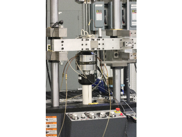
The MTS torsional fatigue rig is composed of a hydraulic torsional actuator capable of applying torques > 2000 in-lbs and a 5000 in-lbs torque cell. Specimens are secured in custom grips between the two and are subjected to static or fatigue strength testing. The system is often run using fully reversing shear loads at 30 Hz.
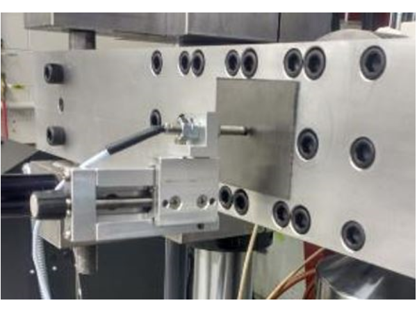
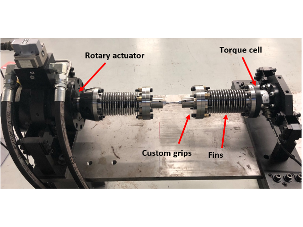
Additionally, a modified MTS torsional fatigue test rig can be used to experimentally measure the S-N behavior of different alloys at elevated temperature. This test rig can achieve a total angular displacement of 90° ( ± 45°) with a resolution of 0.001° measured by an angular displacement transducer. The in-line MTS torque cell with the capacity of ± 565 Nm is used to measure the torque applied to the specimen. The rotary actuator and the torque cell are mounted on a rigid flat base with the rotary drive fixed to the base at one end and the torque cell mounted on a slider attached to the base such that allowed for different size specimen. Two customized cooling fins are designed, developed and attached on both ends of the grips to dissipate heat and prevent heat conduction to the actuator and torque cell. In order to apply torque to a specimen accurately and repeatedly at high temperature, custom grips are also designed and machined which secured the specimen from any rotation and/or slip during the tests. A customized heater can be used to perform the test at high temperatures up to 1000 C.
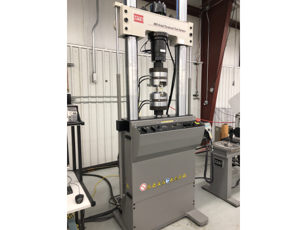
New to the lab in November 2019, the MTS axial torsional fatigue rig is composed of a hydraulic linear and torsional actuator capable of applying loads and torques of 100 kN and 1100 N-m respectively. Additionally, specimens are secured in custom grips.
Material behaviors for metals such as plastic flow and yield strength are known to vary due to applied hydrostatic pressures (Bridgman (1935), Crossland, B. (1954)). Futher, Burns et al. (1964) performed torsional fatigue on solid and hollow steel specimens while inside a pressurized oil. Their results demonstrated an improvement in fatigue life as the material is subjected to higher fluid pressure. In Rolling Contact Fatigue (RCF) high pressure are applied at the contact surface and this results in large compressive principal stresses in the material. Differences between the principal stresses results in high shearing stresses in the material. Crack initiation and ultimate failure is a result of the shear stress in the material. Therefore, the addition of the axial-torsional fatigue test rig to our capabilities will allow us to investigate the effect of hydrostatic pressure on bearing steels subjected to torsional fatigue.
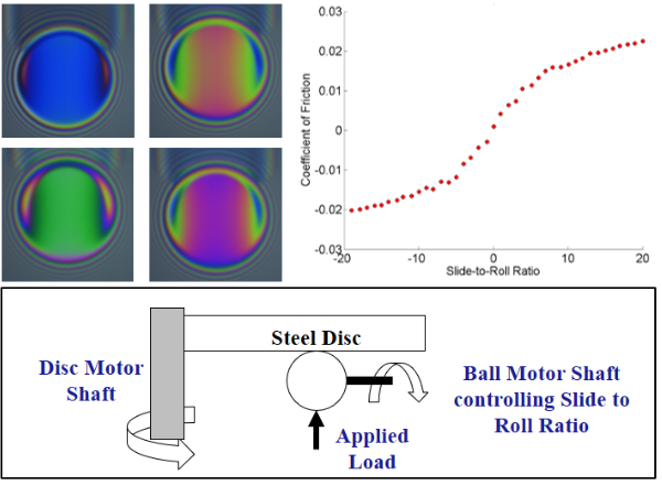
Measures thin films produced during elastohydrodynamic lubrication through the interferometry. An RGB camera captures images of sphere in contact with a flat glass or sapphire disc. These colors are then used to calculate nanometer film thicknesses occurring under the contact. Measure the coefficient of friction as a function of temperature, load, speed, and sliding.
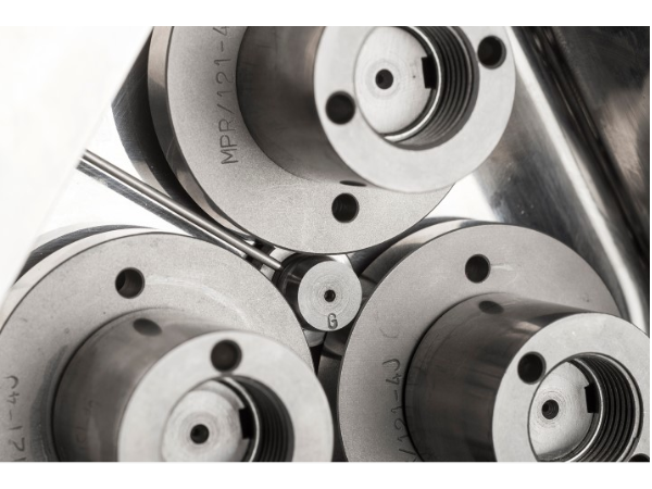
The MPR allows for easy access to monitor specimens subjected to RCF. The system includes two independent electric motors which are attached to the specimen and contacting rings, respectively. This enables precise control over the slide to roll ratio to investigate the effects of sliding on surface deterioration. The rig is also equipped with sensors to measure temperature, wear, and friction during the test.
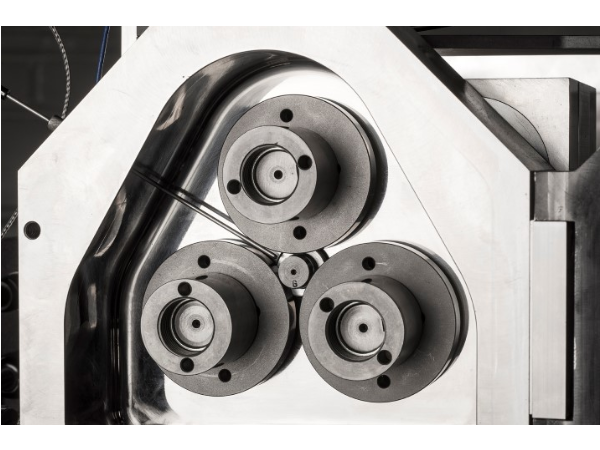
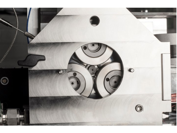
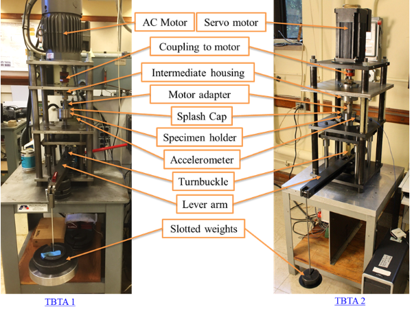
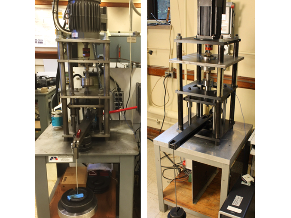
A thrust bearing test apparatus (TBTA) was designed and developed to study the rolling contact fatigue of different materials. The design of this test rig was influenced by the five-ball fatigue tester developed by Zaretsky. The TBTA consists of a five horsepower AC motor used to rotate a shaft that retains an upper race of a thrust ball bearing. The load was applied on the flat specimen through the specimen holder using a dead weight system attached to a lever arm. In this mechanism, the load is applied to the specimen holder by a turnbuckle which distributes the load uniformly to all of the balls. The lower race of a thrust ball bearing was replaced with a flat specimen which was then subjected to fatigue. The flat specimen was fixed in the holder while the upper race was connected to an adapter rotated by A.C. motor. An accelerometer was attached to the specimen holder to detect critical bearing faults such as spalling. In this set up, when the vibration level exceeded a threshold level the test was stopped using LabView software.
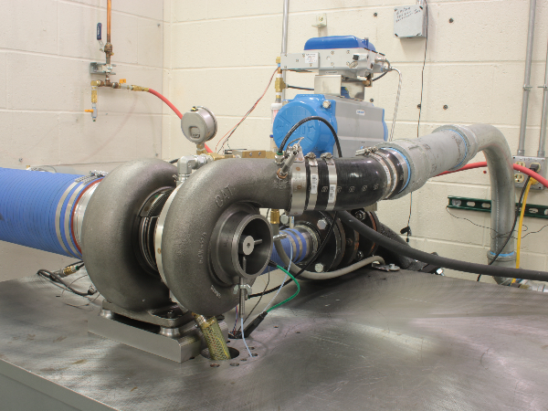
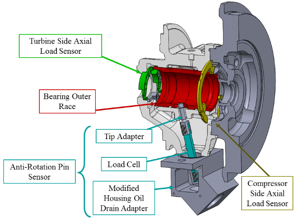
The turbocharger test rig (TTR) is a cold gas turbocharger test stand developed for characterization of the bearing system in ball bearing turbochargers. Ball bearings are replacing journal bearings in turbochargers due to their low friction characteristics which not only increase overall efficiency of the powertrain but also reduce turbocharger lag. To support the rotating assembly of a turbocharger, two opposed angular contact ball bearings are integrated into a single cartridge and supported on a squeeze film damper. Air to drive the turbocharger is provided by a diesel air compressor while oil for lubricating the bearings is supplied from an external heated reservoir. Two proximity probes are positioned 90° apart in the compressor housing and measure shaft whirl from the compressor wheel. In the turbocharger the bearing cartridge supports both axial and frictional loads. Strain gage sensors were designed and machined to fit within the geometry of the turbocharger on either side of the bearing cartridge to measure axial loads. The anti-rotation pin, which typically supports the frictional load on the cartridge, was replaced with a beam load cell and adapters to simulate the geometry of the pin.
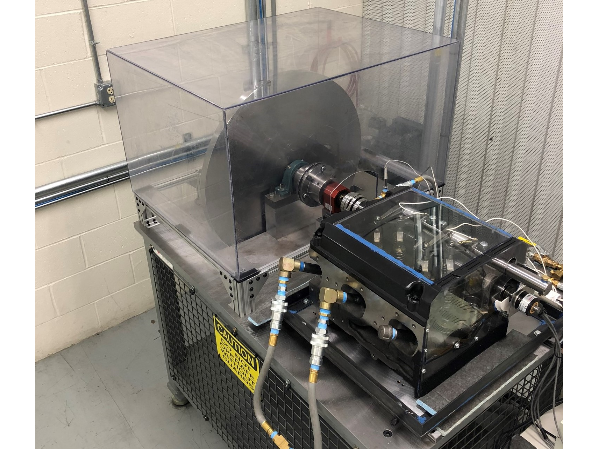
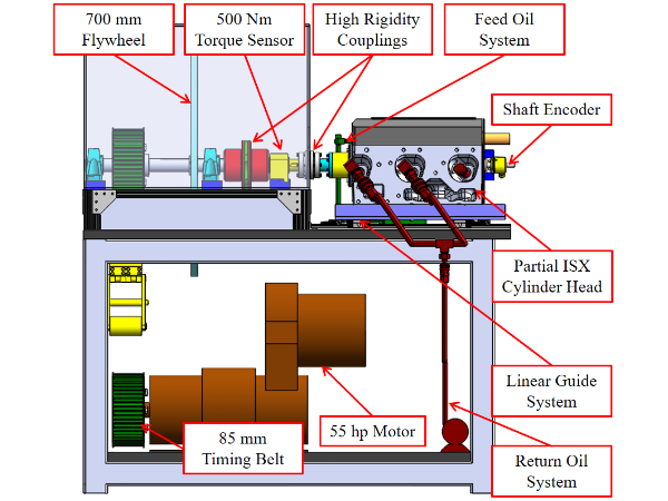
The cam and follower valve train test rig (VTR) was developed to measure the individual angular speed of the intake and exhaust rollers. The camshaft is driven by a 55 horsepower electric motor through a timing belt configuration. A 700 mm flywheel is attached to the drive shaft for stability purposes. High rigidity couplings allow for in situ torque measurements of the camshaft. Equipped with sponsor proprietary speed sensors, the VTR measures the angular speed versus angular position of the cam. Since the VTR cams are non-circular, the speed of the roller followers does not remain constant, the choice of measuring the roller speed versus angular position was clear. To relate the sponsor’s speed sensors to angular speed, a LabVIEW code was developed to take full advantage of the 40 MHz clock onboard a compactRIO and within the FPGA layer. The measured roller speed data is compared to the theoretical roller speed profile, which is developed from cam and follower kinematics. Differencing present between the measured and theoretical data is utilized to characterize the slipping and skidding of the system.
The cam follower test rig (CFTR) is a custom built test setup for characterization of follower performance in cam-follower designs. The CFTR uses a circular cam profile to maintain a constant input speed and load during the cam rotation. A constant normal load is applied on the follower using a hydraulic actuator. The torque and the coefficient of friction developed in the system is measured using a rotary torque sensor. The test setup is mainly used for:

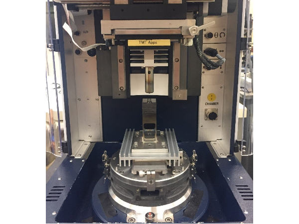
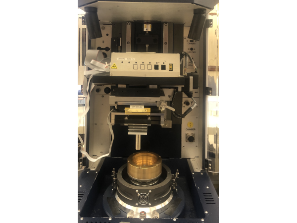
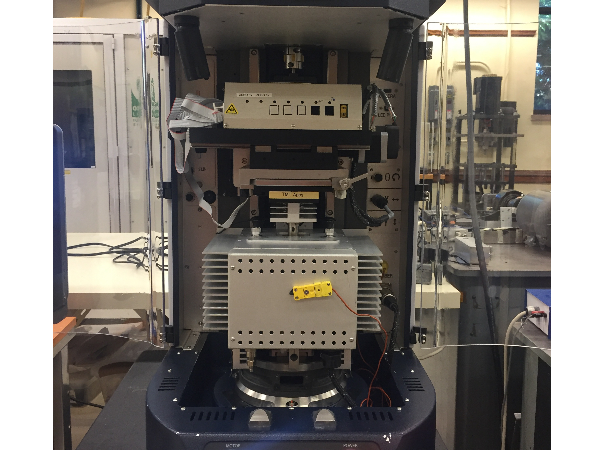
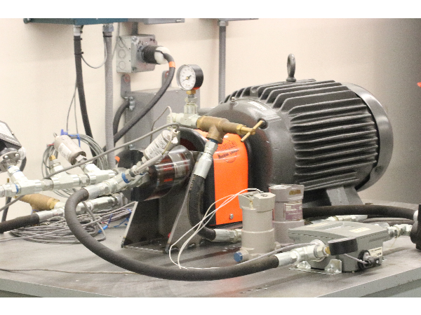
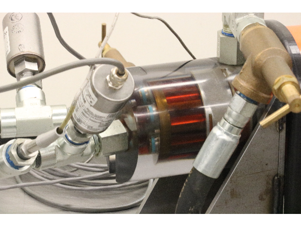
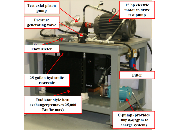
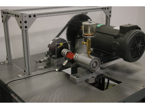
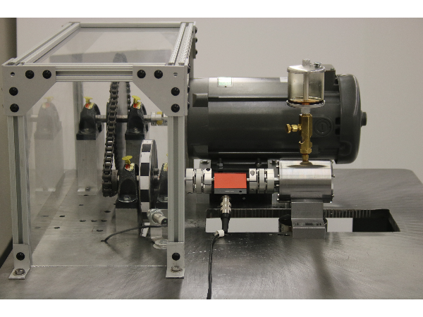
An axial piston pump test rig was designed and developed to operate pumps and measure the lubricating gap between the valve plate and cylinder block. The hydraulic circuit used is based on a general design for steady state testing of axial piston pumps commonly used in industry. The APPTR is instrumented with flow meters pressure transducers and thermocouples to measure and control the desired pump. A series of pressure relief valves are also used to control the pressure in the hydraulic lines and generate a hydraulic load on the pump. The axial piston pump is driven by a variable speed 15 hp electric motor which can operate at up to 3600 RPM. Through the use of 3 non-contact proximity probes mounted in the pump housing the valve plate motion and film thickness between the cylinder block is measured. This test rigs allows for a better understanding of valve plate motion and film thicknesses in axial piston pumps.
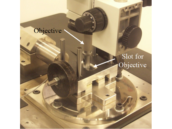
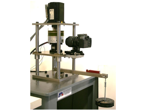
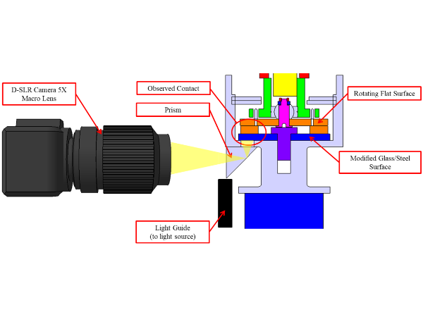
A pocketed thrust washer test rig (TWTR) was designed and developed to experimentally measure the cavitation and shear driven cavity flow inside of surface modifications using optical measurement techniques such as Particle Image Velocimetry(PIV). Any desired lubricant can be used in the reservoir as well as any desired pocket geometry or orientation. An encoder is used to measure and control the servo motor speed. The rotating runner is coupled to a ball and socket joint and attached to the servomotor. The ball joint configuration allowed the runner surface to adjust and remain parallel to the bearing surface. A 10:1 load arm is employed to apply any desired load onto the bearing. Using the camera mount on the front of the test rig, the flow inside of the pocket geometry is then visualized through the use of a prism and a glass sight.. This test rig allows for a better understanding of the recirculation and cavitation effects that occur when using surface modifications on bearing surfaces.
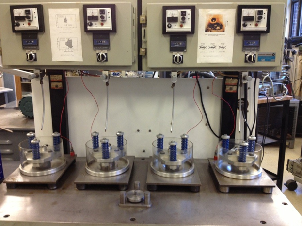
A simple but effective rig for running large amounts of RCF specimens to produce material specific Weibull life distributions. Two machines with 4 heads each are composed of electric motors with a specialized collet pressed onto the shaft for securing specimens. An apparatus is placed over the specimen putting three balls in contact with the rod specimen. The test is run until the vibrations become to large, indicative of surface degradation or failure.
The Four Bearing Test Rig was designed and developed to measure frictional torque of rolling element bearings under different load and speed conditions for various lubricants and lubricant fill levels. An inline torque sensor is used to measure the frictional torque of a four bearing system under axial load over inertially controlled rundown tests driven by a flywheel. Speeds up to 6000 RPM are achieved before the electric motor which drives the system is disconnected to initiate the rundown tests. Radial loads up to 300 lbs can be applied to the system of four rolling element bearings, which are loaded in a double-shear configuration. Bearings which have been tested include radial needle roller bearings and deep groove ball bearings. Lubricant fill level and circulation can be observed through and acrylic end-cap on the four bearing housing.
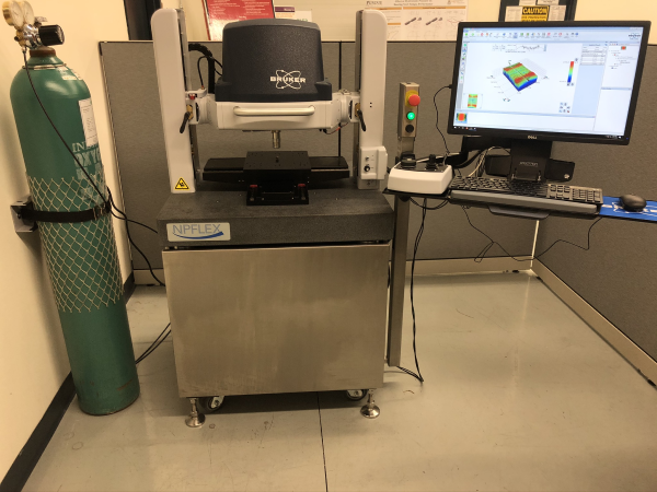
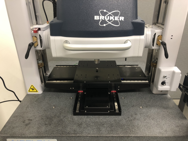
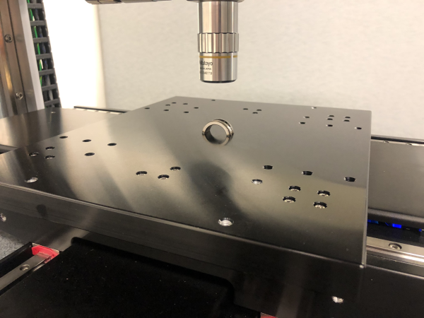
The examination of tribological surfaces is a critical issue in the field of tribology. Especially in lubrication, we commonly encounter film thicknesses that range from 1 micron all the way up to 10 microns. Thus it is very important to be able to understand and measure the surfaces we interact with. As the name suggests, our optical surface profilometer is a non contact, optical measurement device. The profilometer makes use of the reflecting light of a given surface to calculate the intensity and subsequently the height of the surface. Our Bruker NPFLEX optical profilometer, new to the lab in November 2019, can measure the surface profile of objects with a resolution to less than 0.1 nm. It features a fully automated XY stage with ~250 millimeters of working area and the ability to give the surface roughness of the specimens at different magnifications, such as 2X, 5X, and 10X, with crash mitigation assembly. The open gantry measurement head design allows for the lens assembly to be raised to up to 13 inches above the XY stage. The associated Vision64 software is capable of stitching up to 2500 individual scans together to create one large, detailed image of a surface.
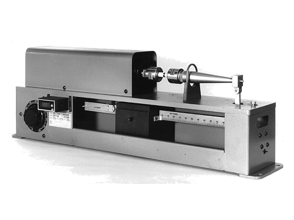
The bending fatigue testing machine examines the classical bending fatigue phenomenon. Once a cylindrical test specimen has been placed into the machine’s bearing, load is applied to the specimen. This rig utilizes hanging weights to place the cylindrical test specimen in bending. Once secured, the bending fatigue testing machine rotates the specimen. Since the specimen is under load, a stress reversal is produced, which induces bending fatigue.
MECHANICAL ENGINEERING TRIBOLOGY LABORATORY
Purdue University, West Lafayette, IN 47907 USA, (765) 494-4600