Adam Boeckmann - Senior Design - Fall 2008 - Group 2
Week 01
Met as a team prior to class to discuss preliminary project proposal. Decided that the workout buddy should not include an mp3 player but should instead give an auditory cue during and after exercises. We also decided that it should be able to monitor and report on your heart rate, distance run, and number of repetitions for various routines. The following is a summary of the basic feature set we'd like to implement.
- be able to count/monitor/record exercise movement repetitions
- record stride/running information
- record/monitor heat rate and calories burned
- interface with a PC for workout "play lists" and to track/plot data
- record movement data for use with other software to display body movement for training purposes (such as rifle shooting and golf swings)
- be able to create new exercises on the fly and "add" them to the library of exercises
- use accelerometers to gather data. Must be removable (ie can be used on wrist or ankles, but not at same time)
- use a rechargeable battery (possibly charge over USB) in the main unit
- accelerometer monitor should be wireless
In the evening I setup the web site, including the template design and notebook layout. I changed the password for the group account and notified all members of the changes.
I submitted the team building and project idea:
I created the lab notebook directory and updated the lab notebook templates.
Accomplishments: Submitted preliminary project proposal and have a good understanding of what we want to accomplish on the project.
Weekly Work Total: 6
Project Work Total: 6
Week 02
Met as a team after class and reviewed proposal PSSC comments. Decided we would not use GPS, as the unit will primarily be used indoors. We also decided to focus most of the features on the device around the use of the accelerometer.
In the evening I created a power point presentation for our PSSC presentation on wednesday.

We met to discuss our pssc's and finalize our design features. The Workout Buddy will consist of three units. The main unit will be belt or arm worn and will have a LCD screen, a scroll wheel and buttons, a small speaker and a USB connection. Using this main unit, the user will be able to select and create exercises and exercise routines through a GUI. The unit will provide feedback via the speaker on exercise progress.
Our proposed PSSC's are as follows:
- An ability to give the user audio cues during exercise routines
- An ability to transmit data from accelerometers through a wireless protocol
- An ability to learn new exercises based on user movement
- An ability to navigate GUI through LCD display using external mechanical interface
- An ability to recharge and upload statistics via USB
Our Proposed PSSCs as well as our initial block diagram and team member duties can be found in our homework 2 hand in below. The projected cost of our project should fall somewhere between 200-300 dollars.
Accomplishments: The pssc's were finalized and an initial block diagram was created. Individual duties were assigned and an initial project cost was created.
Weekly Work Total: 5
Project Work Total: 11
Week 03
Reviewed PSSCs and feature set. Looked at parts to get an idea on what is available. Will meet with group on sunday to discuss and decide on parts.
We met to discuss, review, and decide on parts. However, the topic of Villanova came up and we decided to talk with Prof. Meyer before going any further.
Accomplishments: Not much accomplished this week as we want to talk with Meyer in regards to Villanova as there is interest within the group on that project
Weekly Work Total: 2
Project Work Total: 13
Week 04
Drew, Michael, and I met with Prof Meyer and Prof Johnson today to discuss Villanova. Many of our questions where answered on how deadlines would work as well as other standard 477 requirements. We decided to discuss it over and get back to Meyer with a decision.
After talking it over with group members we decided to shift gears and take on the Helmet project with Villanova. Johnson was notified and now we are waiting on contact information for Villanova
I read over the email sent from Prof Dougherty from Villanova and discussed a response with the group. We sat down and replied before class today. We'll be waiting for the actual group contact information so we can get started. A copy of the initial email and the response can be seen here.
While we haven't come up with a formal set of PSSCs, we do know what functionality we want our design to include. A summary of those abilities are as follows:
- Use accelerometers to measure the force of impacts on the head.
- Record impact data on a removable memory card
- Use Lithiom-ion batteries w/ a fuel gauge indicator and be able to recharge it from within the helmet
- Send alerts to the sideline whenever a hit is received that is above a threshold indicating a possible concussion
With those features in mind, we can begin the selection of parts. Here is what I found on my initial search:
Accelerometers
- An interesting document on accelerometers can be found here. It goes over what they do, how they work, and most importantly what all the specifications mean.
- According to wikipedia it takes on average around 70g of force to cause a concussion, however this varies based on the person and other factors.
- According to here around 95g of force is an almost guaranteed concussion (equivalent to a 35mph car wreck).
- The accelerometers that Villanova gave us (found here) in their parts list only measures up to 3g. this isn't enough to detect a concussion.
- I recommend these as they measure up to 250g, but can be tuned to measure up to 120g with higher accuracy. They are only single axis, but are cheap and only cost 8$ each.
Wireless Transceivers
- I had a hard time finding any wire-to-wireless converters that were small enough to fit into a football helmet. I found two that look promising, but are expensive
- Wiport - around 120$, security enabled, embedded web server.
- Matchport - around 75$, security enabled, embedded web server.
Battery Charge & Indicator Systems
- All of the systems I found were very affordable (under 3$ each)
- I'm not sure how the fuel gauges or charge controllers wire together. More research is needed here.
- ADP2291 - Charge Controller w/ charge indicator. I liked this one as it accepts up to 12v as input.
- MCP73828 - Charge Controller w/ charge indicator. The one meyer mentioned in class.
- MAX8856 - Charge Controller w/ charge indicator. This one supports up to 14v as input and is certified for USB power. I have several Wall AC to USB power cords laying around (5V, 550mA).
- DS2784 - fuel gauge indicator. This shows charge level but IS NOT a charge controller.
Microcontroller
- Would like one with an integrated Ethernet controller.
- Having one that can accept analog inputs would save the need for AtoD converters for the accelerometers.
To Do: .. research memory card interface controllers and solutions, Speak with chuck on monday for wireless recommendations in case he is aware of a better solution. We need to get a parts list to Villanova before monday!
Had a meeting with the Villanova team over AIM and discussed the feature set our helmet will include:
1. Use of a Lithium Ion battery in combination with a charge gauge.
2. Ability to alert sideline personnel in the case of a major impact.
3. Monitoring of impacts through the use of accelerometers.
4. Record the data on a removable device on the helmet.
A copy of our first conversation can be found here.
Accomplishments: A lot was accomplished this week. We got an initial parts list put together with a few options. We narrowed down the feature set with Villanova. The next thing we need to do is solidify our parts list.
Weekly Work Total: 9.5
Project Work Total: 22.5
Week 05
We had a chat meeting with Villanova over Google chat today and discussed parts. We were able to narrow all the parts down fairly easily with the exception of the processor. Villanova wanted to use the ARM Xpress processor. Here is a list of what we chose:
Accelerometer : (MSP1004 / MSP1005)This was the only 3-axis accelerometer we found that was sensitive enough to measure impacts at the levels we needed. The only concern here is availability.
Wireless Transreceiver : (Matchport) We chose this because it was cheaper than the Wiport, had the exact same features, and had a wide variety of antenna mounts.
Microcontroller : (PIC16) We chose this family as it has all the options we need. Several ATD channels, low power consumption, cheap, and easy to work with. We convinced Villanova to use this processor as it is much better suited to the application than the ARM Xpress Micro.
Battery : (LIR18650) We chose our battery based on a power estimate we drew up. We'll need roughly 2200 mAh to power our device. This battery fits the bill and is a rechargeable Lithium Ion.
Battery Management :(Not Specified) We've decided to go with the Maxim brand battery management circuits because they have carry both the charge management and fuel gauge indicators. Both of which, have been used in prior senior projects on a wide variety of Lithium Ion devices.
We gave our design constraint presentation today during class and received some good feedback from classmates. We didn't take into account that more than 1 accelerometer might be needed to accurately read collisions. Since the head can rotate during a hit, an accelerometer might not measure the extra force generated by the rotation. It would take at least 3 accelerometers to provide an accurate reading in this situation. I shot an email out to my group mates about this. Unfortunately I will be out of town until Sunday.

Accomplishments: We narrowed down our parts. This was a big accomplishment because now we can work on design and packaging without having to work real closely with Villanova. This will allow us to catch up with the rest of the class.
Weekly Work Total: 5.5
Project Work Total: 28
Week 06
I met with Michael and Drew and we discussed using more than 1 accelerometers as was suggested by a classmate. We decided that it would indeed be a good idea to use more than 2. Since it takes 3 points to form a plane, it would take three 3-axis accelerometers to measure rotation and overall acceleration.
It's worth mentioning that the field of concussion in sports is under ongoing research and there is no set in stone parameters for detecting concussions. This is another reason we decided to implement 3 accelerometers.. to allow for measurement of rotational force.
We also decided to upgrade our processor to another pic16 with more I/O pins and ATD converters. After looking over the PIC processor options, we've settled on the PIC16F887, as it has 14 ATD channels, plenty of I/O pins and the most RAM available of the series.
Later that night, I started working on the packaging presentation for wednesday. I looked for competing products and found the Riddell Revolution IQ HITS helmet. It costs $1000 and has 6 accelerometers. The packaging on the helmet was rather interesting. It breaks its PCB into several smaller PCBs enabling them to fit into the helmet better.
I also did a bit of brainstorming on the WIFI connection we're using. I read over the spec sheet a bit more and came up with the idea to use the built in email notification of the matchport to alert sideline personnel over email (or pagers if able).
A lot of stuff got accomplished today. Parts are almost finalized. We met after class to discuss Kevin's report, my presentation, and to put together a part order list. We reviewed Kevin's report and made some suggestions. Then we talked about my presentation and decided to use the email notification feature as the means of notifying sideling personnel.
Then we started putting together the parts list and when we called Digikey we found out that the accelerometers we were planning on using (MSP1004) were no longer manufactured. We contacted Villanova since we thought they had already ordered parts. After talking with Francis, we found that they had encountered the same problem. He recommended using the 3g accelerators that they initially suggested or using pressure sensors instead of accelerometers. After crunching a few numbers it was decided that neither would be sufficient to get the data needed to adequately determine impact severity. A copy of our conversation can be found here.
We spent the next few hours going through web site after web site looking for replacement accelerometers. We called a lot of suppliers and no one had any available accelerometers that were in stock and under 700$. Finally Drew found some that were available from Freescale. However, instead of going with single 3-axis accelerometers we have to go with three 1-axis accelerometers. The accelerometers we will be going with now are the MMA2301 and the MMA1212. They both share the same electrical characteristics, but the 1212 measure the z-axis and the 2301 measures the x-axis. They are small enough that we can easily mount 3 per location (3 locations total) inside the helmet.
Later I finished up my packaging presentation for wednesday. I also spoke with Drew later that night and we made the decision to upgrade our processor to the PIC18F45K20. It has just as many ATD channels, same number of I/O pins, but more on board memory to handle the C compiler and stack routines. It is also the same price as the PIC16s.
Drew also found this piece of hardware. It's interesting and definitely worth looking into when we build the power circuit.
I updated the web site with a documents page to keep all our reference material, homework, and presentations. I also spoke with Kevin and he strongly suggested using only 1 accelerometer. At this point I don't see a reason to change our design yet again. There is nothing you can do with 1 accelerometer that you can't do with 3. Three accelerometers will be more accurate in measuring both overall acceleration and rotation of the head.
I also updated my presentation to include our new changes as well as an overall update on our progress. I feel since we've only been at this new project for 2 weeks now and we've had significant changes in our design and parts selection since last week, I should present it to the class and get more feedback on our direction. Below is a link to our packaging presentation:

I spoke with Louis from Villanova for a quick parts update on the accelerometers and microcontroller changes. Villanova is going to meet later and go over parts and look at the power circuit. Our chat can be viewed here.
I worked on the paper and got most of the sections done. We also reviewed parts and realized that several of our power components were the wrong packaging. After a bit of searching, we came up with a new charge controller (MCP73838). It is a simple 1 cell battery controller and has less pins than the previous. It also comes in a compatible package. Another fuel gauge was chosen, however it was later changed.
Afterwards, Michael and I drove around to several sporting good stores and checked for football helmets. Unfortunately no stores in town stock helmets at this time of year.
I spent a few hours working on the paper. I had Jen proofread it for grammar and the rest of the group check it for content. I made a few changes, mostly grammatical, and turned in the paper. We also sat down and updated the schematic. Drew got all the microcontroller pins figured out and assigned. All of the schematics are now finished with the exception of the power.
I updated the reference and documentation page to reflect out new components. I also got all of our data sheets downloaded and placed on our web site for easy access along with links to the product pages. The schematics were turned in. However, as was mentioned earlier, the power schematic is not finished. We plan on talking to Meyer during his office hours on Tuesday to get some advice on how to interface the various parts together. As it stands now we are using power mosfets to switch power supplies between the wall wart and the battery.
Accomplishments: A lot was accomplished this week. We got components nailed down, schematics done, and an almost complete power circuit. After talking with Meyer on tuesday we should be able to finish the power circuit and move onto the PCB.
Weekly Work Total: 32.5
Project Work Total: 60.5
Week 07
We met and talked with Meyer today. He recommended using zeener diodes to select the power source. He also pointed out that the battery monitor uses I2C and we do not have an available I2C interface on our microprocessor. So after searching for another fuel gauge, we came up with the DS2740U. It uses a single wire Dallas64 protocol. We should be able to use it to talk with the micro.
I sat down with Karl and went over the power circuit. He helped me do a VERY conservative power estimate. We chose power parts based off this estimate. Here is a picture of that estimate:
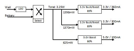
As per above, we started with the required voltage/current of each device and then worked backwards. I factored in efficiencies at each voltage/current conversion (LDO, Buck-Boost, Boost). Using the current and voltage requirements at each step we were able to find relevant parts on digikey. The parts we chose for the components above are as follows:
- 3.3V Buck/Boost - LTC3440
- 5.0V Boost - LT1303
- LDO - TPS75733
We also got the power schematic finished. In the evening I looked at the reset system. I think the easiest way to do this will be to use a flat jumper. This will eliminate the chance of accidental reset during use. It also appears the only two components needing to be reset will be the Matchport and the microcontroller. I passed this information along to Drew and Kevin.
I spent a few hours this morning going over connectors for our PCBs. I want something slim and flat, as height on our pcb is something we need to keep to a minimum. I found these 100mil pins and connectors in the Mouser catalog:
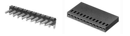
These connectors are ideal, because they lay flat against the PCB and don't take up much space. They come in a variety of input number... from 2 to 12. I gave the specs and information to Drew for his presentation today.
After Drew's presentation, I played around with Orcad Layout. I figured out how to make pads, footprints, and PCB outline. I also spoke with Drew and Mike and got them to break up the schematics into different designs, so that we can get each schematic on a different PCB. I also added bypass capacitors and conductors to the Accelerometer PCB.
I e-mailed Villanova with our updated progress. I also got much more familiar with Orcad layout and fixed all our footprints. I also figured out the spreadsheet system it uses. I got the accelerometer PCB done with no errors and converted into a gerber file. I also did the SD micro with Michael and reviewed a portion of Drew's homework six.
The dimensions of the above board are 1.4 inches wide, by 1.1 inch tall. The schematic and layout files can be found in the reference section of our web site
I helped Michael get all the files together for submission and I threw together our parts list with ordering information for Chuck. All of our rough draft PCB's are done with the exception of Drew's microcontroller PCB.
Accomplishments: Orcad footprint library's were all created, all the schematics were broken up into separate designs. All PCBs are now in a rough draft version. A parts list was created and given to Chuck for ordering. Next we have to work on finalizing the PCBs, by getting feedback from Karl and Meyer. I know grounding planes need to be added.
Weekly Work Total: 27.5
Project Work Total: 88
Week 08
I re-routed the accelerometer board after fixing several footprint errors that we caught over the weekend. Pads on each footprint are now surface mount and don't extend all the way through the board.
I also updated the web site with our schematic and layout files.
Today we had our progress briefing. Mark Johnson and Karl reviewed our PCBs and gave us feedback on them. Most of the feedback consisted of capacitor placement and trace angles. I spent the rest of the evening preparing my section of the design review.
Today we had our design review. It went well and we got lots of valuable feedback. Here is our presentation:
We've decided to combine our SDcard, power supply, and MCU board into one PCB. We also need to re-look at our capacitors and differentiate between polarized and non-polarized as well as give them values.
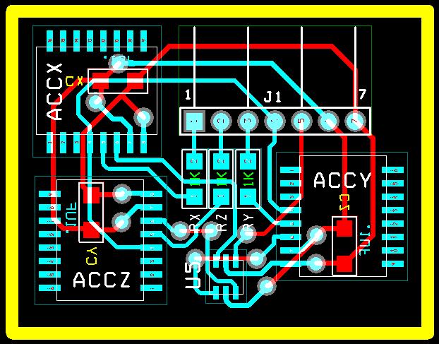
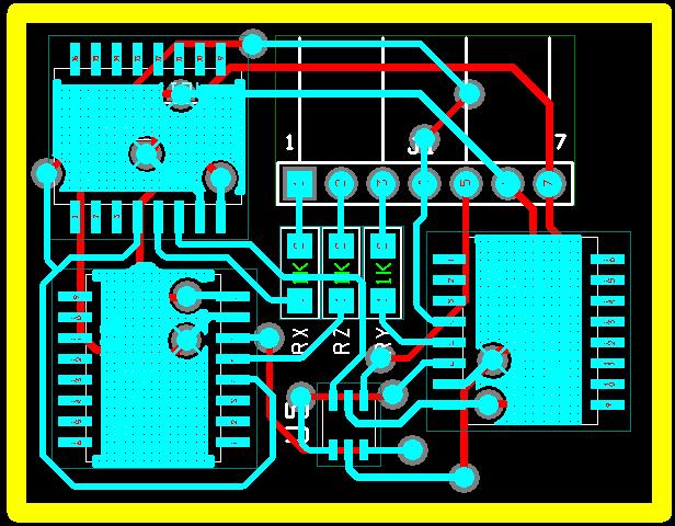
Later I finished the accelerometer PCB by adding the grounding planes and fixing the trace routing. All of the angles are fixed and pads are entered and exited at right angles. Here is a picture of the finished PCB (Top Layer Only):
Here are the notes we took during the questions part of our progress briefings:
- We forgot to add the 100mF electrolytic polarized capacitor on SD card PCB.
- Many capacitors need values, and checked for electrolytic/polarity.
- Electrolytic/polarized on 3.3 V reg on micro PCB
- Wi-Fi polarized vs un polarized capacitor mix up
- Can we remove led from Wi-Fi monitor to save power?
- We need part #'s on regular diodes in the power schematic
- Should change "header" on power to actual header
- Check AND gate vs. OR gate on accelerometer schematic.
- Can we put SD Card onto Wi-Fi
After meeting with Karl we've decided to merge the Power PCB, MCU PCB, and SDmicro PCB into one board. This should cut down on product size by eliminating header spacing, and 2 boards. The Wi-Fi board and Accelerometer boards will remain separate, however. We also plan on addressing many of the above issues over the weekend.
I met with Michael and Kevin. While Kevin worked on the Matchport PCB and Michael worked on the MCU PCB, I familiarized myself with the PCB submission process. I updated the accelerometer PCBs with the correct borders, generated the necessary gerber files and submitted it to the freedfm web site for approval. It came back with no errors.
I also double checked the and/or gate for the accelerometer circuit. We were indeed correct in our use of an or gate because the accelerometer only outputs high if there is an error. By or'ing them together, we can detect when any of them do not work. I also changed the header on the power schematic to more accurately represent a connector.
Accomplishments: The accelerometer PCB is done and ready to be submitted. Our Wi-Fi and MCU PCBs still needs a bit of work. We eliminated our power and SDMicro PCB by moving those parts onto the MCU PCB. Our MCU layout still needs a lot of work and that should be the big priority next week.
Weekly Work Total: 20
Project Work Total: 108
Week 09
I re-routed parts of the Wi-Fi board to better place critical capacitors and inductors closer to their respective pins. Then I started finding some part numbers and footprints for some of our larger capacitors. Here is what we picked out:
Part |
Package |
DigiKey Part No |
MCU |
WiFi |
Accel |
TOTAL |
3440 capacitor (10uF) |
805 |
587-1943-1-ND |
1 |
1 |
0 |
2 |
3440 capacitor (22uF) |
1210 |
587-1384-1-ND |
1 |
1 |
0 |
2 |
LT1303 inductor (22uH) |
Custom |
308-1445-1-ND |
1 |
0 |
0 |
1 |
| 3440 inductor (10uH) |
Custom |
308-1541-1-ND |
1 |
1 |
0 |
2 |
Drew and I worked a bit on our MCU PCB and schematic. We made a lot of minor changes including:
- We dropped the zener diode and USB input on the charge controller as well as the zeener diode on the wall wart PSU since there is no USB power.
- We changed the zeener diodes to regular diodes in the PSU selector circuit because we will not be running them in reverse bias.
- The fuel gauge had no units on its spec sheet for any discrete components, so we fixed this.
- The thermistor in the monitoring circuit was changed to a resistor as per the data sheet (thermistor was optional).
- We removed the redundant bulk capacitor (C19) on the MCU board.
- We updated the LED's to through hole footprints for the charge indicator.
- We updated the debug header to 5 pins as per the MCU development board instructions.
- I fixed the number of pin outs on the MCU board to 9 from 12 so that there are no unused pins.
I finished routing the MCU board. I had to update several footprints in the process. I have not double checked all the footprints on the discrete components. However, I did fix a few diode footprints to through hole. I left a note for whoever came in the next day to start checking the discrete components for part numbers, values, and footprints.
I also reviewed Villanova's circuit schematic and gave them feedback. The major thing I noticed was in their ATD conversion process. The accelerometers run at 0-5V while the MCU ATD channels run at 0-3V.
We had our progress briefing today and there were no large problems seen by Karl, Prof Meyer, or Prof Johnson. I looked over a few corrections noted by Drew and Michael and went through the PCB and widened traces. I tapered small pads out into larger traces where possible. This board is now ready to be submitted to freedfm. However, since the computer in lab crashes every time we so much as sneeze at a zip file, I've had to move the files onto a USB drive. I sent these files to drew for submission to freedfm.
Today was PCB day and we got all of our board submitted. None of our boards came back with any errors from freedfm. We also got several of our parts in.
Accomplishments: All of our PCB as done! Software is next. We'll be going over the development kit next week and come up with a software approach for our design. Hopefully we'll begin coding soon.
Weekly Work Total: 29
Project Work Total: 137
Week 10
We started going over the discrete components in our circuit and building a parts list to submit to chuck for ordering. I also updated a few minor data sheets and references on our web site.
We finished the discrete components list. Here is what we need:
Part |
Package |
DigiKey Part No |
MCU |
WiFi |
Accel |
TOTAL |
| 3440 inductor (10uH) |
Custom |
308-1541-1-ND |
1 |
1 |
0 |
2 |
| 3440 capacitor (10uF) |
805 |
587-1943-1-ND |
1 |
1 |
0 |
2 |
| 3440 capacitor (10uF) |
1206 |
PCC1894ct-ND |
4 |
2 |
0 |
6 |
| 75733 capacitor (47uF) |
1206 |
511-1452-1-ND |
1 |
0 |
0 |
1 |
| 3440 capacitor (22uF) |
1210 |
587-1384-1-ND |
1 |
1 |
0 |
2 |
| LT1303 inductor (22uH) |
Custom |
308-1445-1-ND |
1 |
0 |
0 |
1 |
diode for LT1303 |
Do41 |
497-4547-1-ND |
1 |
0 |
0 |
1 |
| battery connector |
Custom |
455-1127-1-ND |
2 |
0 |
0 |
2 |
| power-wall connector |
Custom |
455-1165-ND |
1 |
0 |
0 |
1 |
We went over the software design and discussed the formulas and coding approaches. We came up with a rudimentary flowchart and decided to use a loop/interrupt mixed approach.
If we run the MCU at 8Mhz and sample at 400Hz, that gives us 8,000,000/400 = 20,000 clock cycles between samples. This should be more than enough to read in the ATD data, do impact calculations, and initiate any store or notify functions.
Today we gave our software design presentation. Before class, I reviewed it and gave a few small recommendations:

Accomplishments: Unfortunately I got sick on Wednesday and was unable to meet with my group on Thursday or Friday. I'll look over their software progress on Monday and that will determine what our priorities are next week.
Weekly Work Total: 6.5
Project Work Total: 143.5
Week 11
We got our MCU PCB in today. Kevin and Michael inspected and tested it to make sure the necessary pins were connected and there were no shorts or mistakes in the routing. I spent the majority of the day working on the Patent and Liability TCSP.
I found a number of patents from www.freepatentsonline.com that pose a potential problem for our product. The Riddell HITS helmet only holds one patent on its electronics (US6826509). This patent covers the positioning of its accelerometers and the algorithm needed to calculate the impacts. Both of these can be averted with our device, so there shouldn't be any problem here.
The second patent is one that governs the use of a mass memory device to log data from head movements in real time, for later study (US5978972). We can subvert this patent as well by removing our 'record' threshold and use our memory card as an 'event log' were it only records notifications and their relative data.
The last patent of interest involves LEDs mounted on a helmet to notify when a dangerous impact occurs (US5621922). This one is a bit iffy as we're not using a 'perceivable' signal. I don't think there would be any problems here, but the potential for argument does exist.
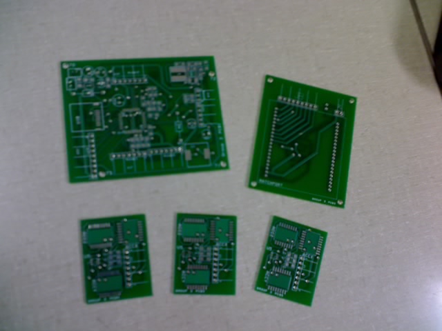
The rest of our PCBs came in today, I checked and confirmed that the board connectors fit:
I polished up the Patent & Liability TCSP before giving it in class today. Meyer gave me some great feedback on what to look for in the patents. I need to re-evaluate the Riddell and mass memory patent as I didn't pay enough attention to the claims.

The rest of our PCBs came in today, I checked and confirmed that the board connectors fit. I spent the rest of the day working on the Patent & Liability homework. I made a number of tweaks from my original analysis based on Meyers feedback.
After studying the claims of the Riddell patent (US6826509), it turns out that there are 3 ideas that must be met to violate any claims.
- The first is non-orthogonal placement of the accelerometers from each other.
- The second is the orthogonal placement of the accelerometers from the body surface.
- The third is that impact direction and magnitude must be calculated.
We violate the first two, but we calculate the magnitude and type of head acceleration not the direction and magnitude of the impact force.
The mass memory patent (US5978972) is very similar to the Riddell patent except its ideas are as follows:
- The first is orthogonal accelerometer placement from each other.
- The use of a mass memory device to record data from the accelerometers.
We violate the second idea. The first idea is open to debate. We use a cluster of single-axis accelerometers to replicate a three-axis accelerometer. While these clusters are non-orthogonal to each other, the accelerometers that make up each cluster are orthogonal to themselves. We can bypass the gray area, but using true 3-axis accelerometers instead of these clusters.
My analysis of the third patent was initially correct. Here is a copy of the Patent & Liability paper:
Michael and I met in lab. He worked on some code examples while I updated our web site. I cleaned up and organized or files and references. I had to fix some links, but the net result is a file structure that doesn't cause a headache every time I look at it.
Michael, Drew, and I met in lab. I wrote an email for villanova and sent that off. I helped Drew with getting the correct components for our accelerometer PCB so that he could solder them.
Accomplishments: We didn't get as much progress on software as I would of hoped. We did figure out MPLab and get some examples working. We got our PCBs in and started soldering. Next week our priority should be on coding.
Weekly Work Total: 25
Project Work Total: 168.5
Week 12
Unfortunately I flipped the silkscreen on all of the Z accelerometers. This resulted in Drew soldering 3 of the 9 accelerometers on backwards. We realized this after testing the finished (ie soldered) boards. Chuck showed us how to remove and clean the components. Drew and I fixed the accelerometer PCB boards and we'll be testing them again tomorrow.
I reviewed Mikes presentation.
Accomplishments: The accelerometer boards are completely soldered and working. WiFi power components are soldered now. Due to limitations in resistor choices, our Boost/Buck output is 3.24V instead of 3.3V According to both the WiFI and MCU data sheets, this is acceptable. Next week we'll get more power components soldered and more progress on software.
Weekly Work Total: 4
Project Work Total: 172.5
Week 13
Drew and I soldered some passive components onto micro controller board for the power circuit.
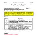
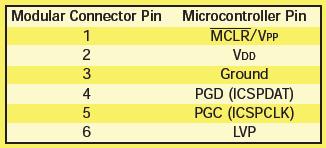
Today I ran around to radio shack to gather some needed supplies. I picked up a 6 wire RJ-6 cables for the programming cable. I cut the wire to a length of 3 feet and crimped the ends. I made sure to stick a 10K Ohm resister between the VDD and MCLR line as per the spec sheet:
We all met in lab today. I got the rest of the MCU board soldered up. After testing the power circuitry we found a problem. Our power selector diodes have ~.7V drop across them. This means that once the battery drop below 3V the buck/boost stops working and the circuit fails. We need to talk to Karl or Meyer about this next week.
I started working on the ethernet cords test software on our device.
I soldered the microSD card and microcontroller as well as the rest of the components onto our main board. However, voltage levels did not appear to be what we wanted. At higher voltage ranges 3.6+ volts, the battery and wall connectors works, but at the lower battery ranges the battery (2.4 - 3.5 volts) the voltage on the micro and other components fell to sub 2V ranges and failed to power anything.
Accomplishments: The micro board is mostly soldered as are the majority of the connecting cables. Next week is thanksgiving.
Weekly Work Total: 17
Project Work Total: 189.5
Week 14
Kevin and I worked on getting the MPLab programming the MCU. I checked the connectors on the cable and they are all ok. The pull up resistor on the MCLR line is also connected correctly. Kevin found some possible solutions on the microchip troubleshooting site. I cut the cable down to 8 inches and stripped the connections. Kevin spliced them.
Accomplishments: Turkey!
Weekly Work Total: 2
Project Work Total: 191.5
Week 15
We all met in lab today and Kevin brought us up to speed on the debugging he preformed last week. However, I disagree with his analysis of the faulty power circuit. I think the reason the Matchport fails on heavy load is due to a voltage drop across the diodes. After measuring and testing this we found that to be the true source of the WiFi power outage.
As a work around to the power problems, we decided to remove the Wall wart LDO and disconnect the wall wort from everything except the battery charger. The plus side of this is that the selector diodes can be completely removed. The downside is that the unit will not work when plugged in to the wall, but will instead charge the battery.
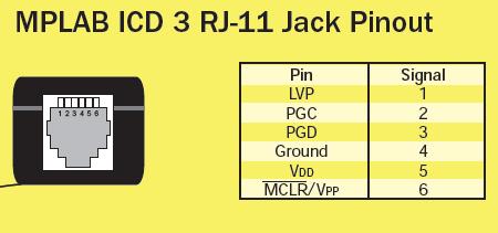
After Drew and I removed the LDO and corrected the circuit as discussed above, we worked on packaging. After brainstorming we came up with the idea to create an 'envelope' out of vinyl and secure it to the helmet with velcro. We also want to use some sort of plasticard material (similar to what credit cards are made from) to keep the shape of the envelope.
This allows us to install the PCBs in a non-permanent yet sturdy way. We can removed the PCBs for debugging purposes but still program it from inside the helmet. After running to Hobby Lobby I was able to pickup all the necessary materials to install the PCBs into the helmet. The Glue takes 12 hours to set fully, so after gluing all the velcro and plasticard, I left for the night to let them dry.
I came in early and checked the glue.. it had set so I finished installing the parts into the helmet. I still haven't glued the velcro to the helmet as I'm waiting to check with Mike and Kevin to make sure the placement of the accelerometers are ok. Once they give me an 'ok' I'll glue the velcro down making it more permanent.
We looked at the MCU / MPLab software and tried to figure out why it isn't running any programs. The MCU appears to be receiving the program from MPLab and I was able to confirm this by pulling up the program memory from within MPLab. Next I looked at configuration registers. I looked over some sample code from online tutorials and it seems that the configurations are set correctly (Watchdog timer, Oscillator, etc...). I did notice that the ports we're trying to output on are flagged as inputs. We changed this but it didn't solve our problem. After reviewing the oscillator settings again we changed it the internal oscillator and we are now getting output on pins.
Today I worked on the user manual. We needed pictures of the web server interface and product packaging for the user manual so our priority today was getting the Java applet up and running as well as the ethernet cables and vinyl envelopes done. I spent the majority of the day on the cables and envelopes as well as mounting them into to helmet. The positions of the PCBs were marked out from when I worked on them a few days ago, and Kevin and Michael were ok with the accelerometer placements, so I glued in the velcro and finished cutting the vinyl. I marked out the pin layouts of the headers and wired the ethernet cables accordingly.
I then spent an hour and created the HTML code for our Java applet. I matched the colors and made it blend in with Michael's java applet:
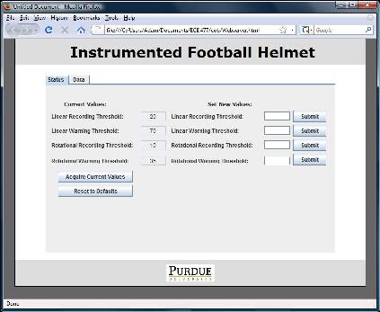
After getting the Web server HTML interface finished, I started on the actual user manual. I wrote up the marketing style introduction which took about a page. Then I wrote up the setup and usage section with pictures and a how-to guide to connecting and configuring the web server Michael wrote up and sent me the troubleshooting guide. I merged them proofread and submitted it.
This morning I spent 45 minutes going over the user guide and fixing a few errors as well as polishing it up a bit. Afterwards I talked with Chuck about our reset circuit and voltage divider. He confirmed my idea for reset works:
This allows us to set a jumper on pins 1 - 2 for runtime, and 2 - 3 for programming. Chuck also recommended I use a total of 10K ohms for the voltage divider circuit. He also said I shouldn't worry about current flowing into the port pins as they typically have an input impendence on the order of mega ohms. We'll just have to make sure we configure the pins correctly.
Our battery connector came loose on our board again. Rather than attached another one to the board, I attached two cables on the board and then placed the battery connector on the end of the cables. This will let help prevent another connector from coming loose from constant connecting/disconnecting of the power supply.
I played with the accelerometer clusters to try and determine why they are drawing 100mA of current instead of the 20mA the data sheet says they should. After re-reading the data sheet and playing with a power supply and extra accelerometers I think I found the reason. The accelerometers enter a self test on boot up and unless the self test line goes high for at least 1us and then drops low, the accelerometers don't leave the self test and draw lots of current. Once Kevin and Michael implemented a boot up self test function, each accelerometer drew less than 30mA.
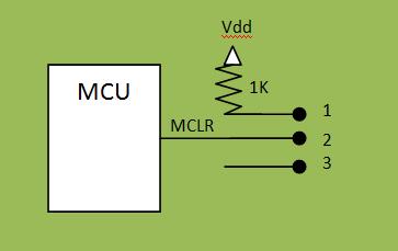
I came in early today so I could work with the micro and not conflict with Michael or Kevin's programming. I reviewed the MCLR line and reset information from the MCU data sheet and found that the master clear line can be configured to be used as an input line instead. This solves our problem as I can tie it to ground without any major fly wiring. Here is the solution:
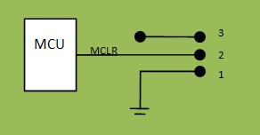
This allows the jumper to be placed in position 1-2 for operation and 2-3 for programming. Next I worked on the voltage divider circuit. My original calculations of 1k, 8k, 1k resistors were accurate for 4.5V and 5V, however it turns out that the vref limits of the pic18 are Vdd + .6V (3.84V) for Vref+ and Vdd - 3V (.24V) for Vref-. This will allow us to read up to +130g and -200g. This just means we'll have to limit our readings to +/- 130g... acceptable. I recalculated the needed resistors for those values and came up with the following values: 2320, 7200, 480 ohm. However, since those resistor values do not exist, I created the following excel spreadsheet to calculate different voltages using available resistor values:
Calculated |
Option1 |
Option2 |
Option3 |
Option4 |
|
| Vdd: (V) | 5 | 5 | 5 | 5 | 5 |
| Current:(mA) | 0.050 | 0.053 | 0.048 | 0.049 | 0.052 |
| R1 | 2320 | 2200 | 2400 | 2200 | 2400 |
| R2 | 7200 | 6800 | 7500 | 7500 | 6800 |
| R3 | 480 | 470 | 510 | 510 | 430 |
| Rtotal | 10000 | 9470 | 10410 | 10210 | 9630 |
| Vref+ | 3.840 | 3.838 | 3.847 | 3.923 | 3.754 |
| Vref- | 0.240 | 0.248 | 0.245 | 0.250 | 0.223 |
Using this table I tried option 2, but found that even when Vref- exceeded the max rating by only .04V the MCU would get a bit warm. In addition the MCU would fail to even program. After scratching my head a bit, Kevin made the suggestion that it might be a stuck in reset problem since the MCU would constantly output a space (a sign that it's booted up). After a bit of digging I came up with the necessary flags to disable Brown Out Resets. (This made sense since the divider circuit puts non vdd/vss voltages on some input pins.) after disabling the BOR and switching resistors to option 4, the circuit works.
We are using 2 input pins on portE for one of the accelerometers. According to Kevin, portE is bad stuff... so I cut the traces and fly wired the two pins to unused ATD channels on the micro.
I also did some research on the battery monitor interface and SD micro SPI interface. I found that microchip has some libraries for SD MIcro - SPI functions. This will make our job on interfacing the SD card much easier. Maxim-ic also has some include files for interfacing the dallas64 protocol to PIC micros. These files are written for pic16s and in assembly but should be mod able to work for us.
Today Drew and I hooked up the fuse and on/off switch. Of course it was just in time as I promptly hooked up ground and power backwards, blowing our fuse... At least we know our fuse setup works.
Later Drew and I started working on the SD card SPI interface. We got our first version of the SPI code in, but we were unable to test it as the computer started acting up. We were tired so we went home. We'll test it tomorrow.
The SPI code was largely borrowed from the Digi-Spy team from a previous semester. We had to modify it to work with our project. We had to make the following changes:
- Reduce write and read block size to 128 bytes. The original block size was 512, but the buffer (also 512) wouldn't fit in our memory.
- Change the read status buffer as it is different for our pic18
- Modify the pin declaration, since our SPI interface is on a different port.
Accomplishments: We got our packaging done and a lot of progress on software. Our accelerometers are sending data, our web server is sending and receiving strings. Our micro is recognizing commands from the web server and 'doing stuff' in response. Our first draft of SD code is up and compiling. Next week we need to finish the SD interface and tackle the battery monitor if we are going to finish by wednesday.
Weekly Work Total: 57.5
Project Work Total: 249
Week 16
On Kevin's request I fly-wired in a 5k pull up resistor on the bat stat data line. Later I looked over the accelerometer "to-g" conversions and found an error in our current calculations. We were performing a 'negative axis offset' to all readings and not just the negative ones. In addition I re-calculated our zero-g point and found that we need to raise our zero-g point a small amount:
| measured Vref- = .234V | Reads from 0 to 1023 |
| measured Vref+ = 3.78V | voltage difference = 3.78-.234 = 3.546 |
| Avg (actual) 0g = 2.625V | reading per volt = 1024/3.546= 288.77 |
| Actual 0g = (2.625-.234)*288.77 = 690 |
Later drew and I took another shot at the SD card. We looked back over Karl's prior SPI code and made a few tweaks. We tried running the code again and still no luck. I probed the SPI lines with the DMM and I saw data going out, but nothing coming in.
After failing again at SPI code v3., I hooked a logic analyzer up to our SPI port so I could see how our timings look. After soldering a test pin onto our SCK line I was able to get all four signals onto the analyzer. I also went through the SD-SPI protocol and tried to annotate the timings so I could get a better feel for out our card should be talking with the micro:
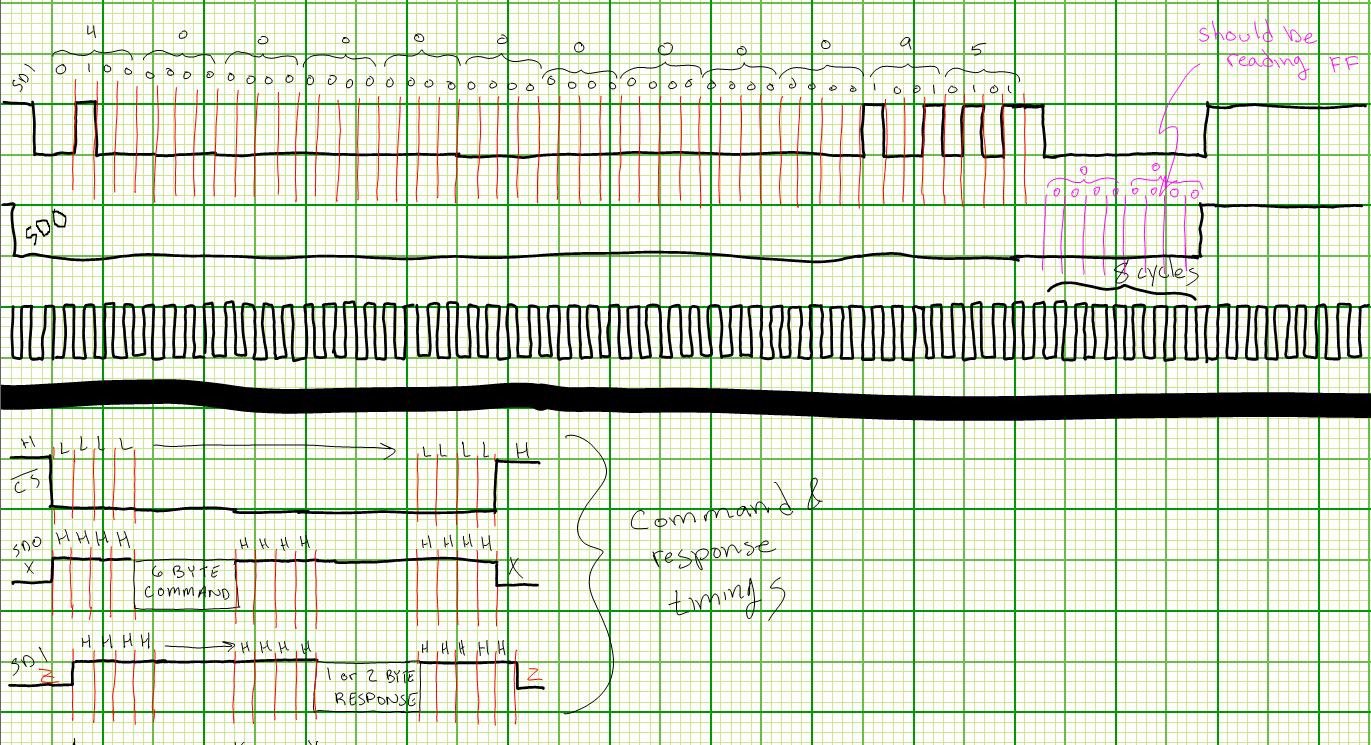
The above picture is a link to the logic analyzer results and the "expected" results. I've noticed that the SDO line is staying low the entire time, and its suppose to be high during input.. just as the SPI line is suppose to be high during output. One thing we have ruled out is needing pull up resistors.. the H-L and L-H transitions are crisp and fall within the timing restraints.
I took a look today at several things to try and narrow down our microSD problems:
- I verified that our microSD card DOES support SPI
- I verified the handshaking protocol timings we are trying to send it.
- I verified that we do NOT need pull up resistors on our MOSI or MISO lines as long as the time(high-low) and time(low-high) are within acceptable range.
- I verified the pin out of the microSD card and our MCU.
I will check these against our actual values tomorrow. Since our SD card is not responding when the CS select goes active, it's got to be either the lack of pull up resistors making it float low or an incorrect pin out on our PCB.
In verifying all of my findings yesterday I found the problem.. our pin outs are wrong. Here is what they SHOULD be:
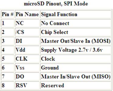
However, we used the standard SD pin out and not the microSD pin out The difference is that the SD pin out shifts pins 2 and 3 up one to pins 1 and 2 and has an extra ground connection on pin 3. After discovering this, I cut traces to pins 1, 2, & 3 and exposed the leads so we could fly wire the pins correctly. After doing this we hooked the microSD card back into the circuit and powered it up...
OUR microSD CARD TALKS TO OUR MCU NOW!!!!
We spent the rest of the day getting the timings down. We still have some work to do on our microSD card so that we can store and retrieve data on it, but we'll get there.
Drew and I met in lab and worked a bit on the SD code. However we didn't make much progress. We can't figure out why our card doesn't appear to actually write anything we tell it too:
- waveforms are correct for a read/write
- correct command is being sent
- card responds correctly
We did notice that the "writeString", "writeVar", and "writeVariable" functions don't seem to work correctly when called from within our SD file. (or at least that's our theory)
Couple big changes today:
- we reverted much of our code back to what Karl originally had(minus pin declarations and I/O directions). It seems we made some changes during our week of SD card frustration that was messing with how the blocks were writing.
- Kevin solved the buffer problem by re-allocating memory in the linker script (something I didn't know we could do). With a 512 byte buffer it made our coding a lot easier.
- Mike moved the write functions into a header file, this allowed them to work correctly when called from within the SD card file.
After much debugging we traced our read/write problem to its source.. the assignment of our desired read data into the buffer wasn't actually assigning anything into it. The syntax is correct: ( buffer[count] = input ). After checking the linker file, Kevin realized that when he assigned memory to the buffer he had made it read only... DOH! After fixing this our SD card worked flawlessly.
I began work on the deliverables due on Monday. The ECE Senior Design Report is now done. I also updated our documents & files section of our web site. We're going to demo what we have to Karl tomorrow before we try actually charging the batter via the circuit (incase it blows something up).
I updated my professional and design papers to fit into the final paper and submitted our ECE Senior Design Report. I also started the poster and helped drew debug the microSD code.
Accomplishments: Got the microSD card completely working and the papers started. Seeing as how the papers are due tomorrow, they will be our primary focus. As it stands now, we are able to demonstrate 5 of our 5 PSSCs. It's been a long journey but a rewarding one.
Weekly Work Total: 56.5
Project Work Total: 305.5