Lab Notebook of Thomas Pansino
Week 01
January 9, 2013 (1 hour)
- Met as a team to discuss project idea and decide team roles.
- Drafted preliminary project proposal.
January 10, 2013 (1 hour)
- Researched components online.
- Purchased Raspberry Pi for experimentation.
WEEK 01 SUMMARY
- Accomplishments: Drafted initial project idea, researched and purchased microcontroller for experimentation.
- Weekly Work Total: 2 hours
- Project Work Total: 2 hours
Week 02
January 14, 2013 (1 hour)
- Set up Lab Notebook webpage.
January 16, 2013 (2 hours)
- Set up Git repository for games and loaded in Asteroids.
- Configured Eclipse on both my and Jackie's computers to work with the new Git repo.
- Met as a team to discuss initial project idea feedback and brainstorm new ideas and options.
- Formulated some inital PSSCs
January 17, 2013 (6 hours)
- Met with both Dr. Johnson and Prof. Meyer to discuss new project options and ideas. Prof. Meyer suggested adding a TFT screen to the project to fulfill the necessary requirements. Current project idea is now a gesture-controlled table top arcade machine complete with built in audio, video, and gesture recognition devices (Leap Motion Controller preferred, Microsoft Kinect as a backup).
- Completed Final Project Proposal.
WEEK 02 SUMMARY
- Accomplishments: Set up Lab Notebook webpages, Git repository, and software development environment. Discussed project feedback with professors and wrote final project proposal.
- Weekly Work Total: 9 hours
- Project Work Total: 11 hours
Week 03
January 22, 2013 (5 hours)
- Emailed Leap Motion again about joining Developer Program. Attempted to call but was directed to voicemail.
- Researched microcontrollers and components.
- Met with team to discuss feedback from Final Project Proposal. Brainstormed new ideas for project and decided to favor switching to a modern version of the classic game Rock'em Sock'em Robots controlled by a Kinect.
- Prepared presentation for TCSP 1 with information on both project ideas and plan to get direct feedback from course staff on new idea tomorrow.
January 23, 2013 (2 hours)
- Met as a team to work on HW2 (Eagle tutorial). Could not find parts in libraries to finish assignment, so postponed completion until tomorrow after consulting TAs.
WEEK 03 SUMMARY
- Accomplishments: Switched project idea to modern Rock'em Sock'em Robots.
- Weekly Work Total: 7 hours
- Project Work Total: 18 hours
Week 04
January 27, 2013 (4 hours)
- Set up and tested Raspberry Pi running "Raspbian" OS. Need to figure out how to attach and run Kinect next.
- Met as a team to discuss overall design and refine intended feature list.
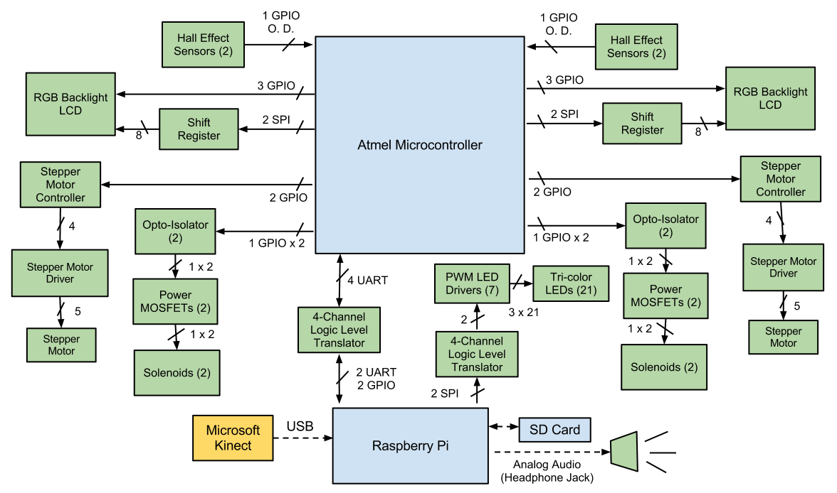
- Created more detailed block diagram and divided up work of researching parts for various systems.
January 28, 2013 (1 hour)
- Met as a team to finish HW2.
January 29, 2013 (5 hours)
- Met as a team to research primary components for design. Most components, excluding power supply components, have been identified, though calculations as to their usability with other parts still need to be done.
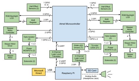
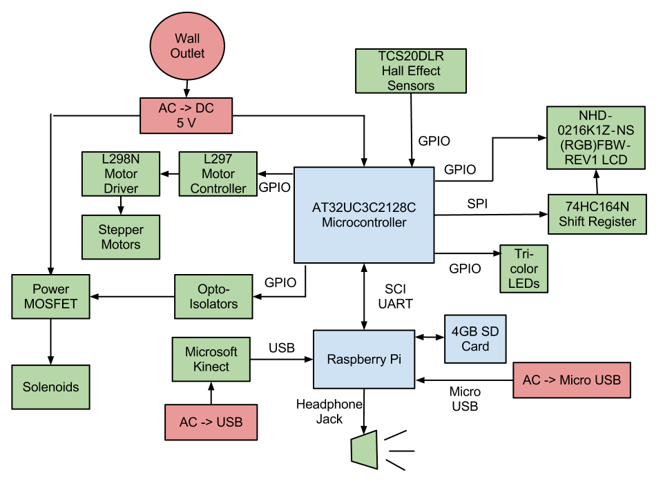
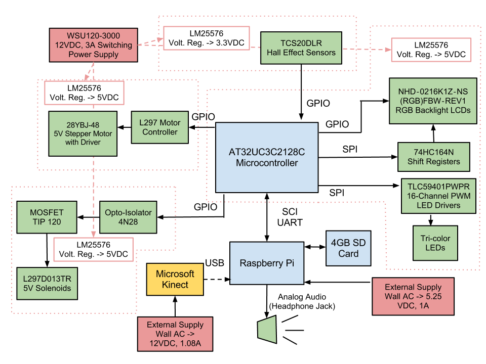
- Calculated number of pins required for microcontroller as well as constraints and requirements of various on-chip peripherals needed. Updated block diagram is shown below:
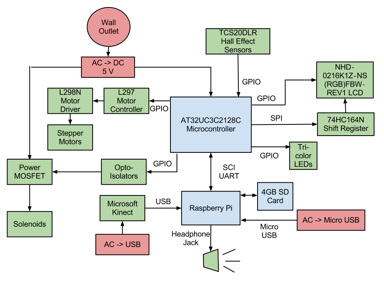
Results are summarized in TCSP #2, which can be downloaded here.
- Searched both Atmel and Microchip websites and compared best matching chips for our projects. Decided to go with the Atmel AT32UC3C1512C over the Microchip dsPIC30F6014A because the AT32UC3C offers much more in terms of on-chip peripherals for only a few dollars more, leaving room for experimentation and design changes. It also has more internal Flash memory and SRAM.
- Created TCSP #2 presentation and uploaded to website.
- Organized website files a bit and adjusted links accordingly.
January 31, 2013 (8 hours)
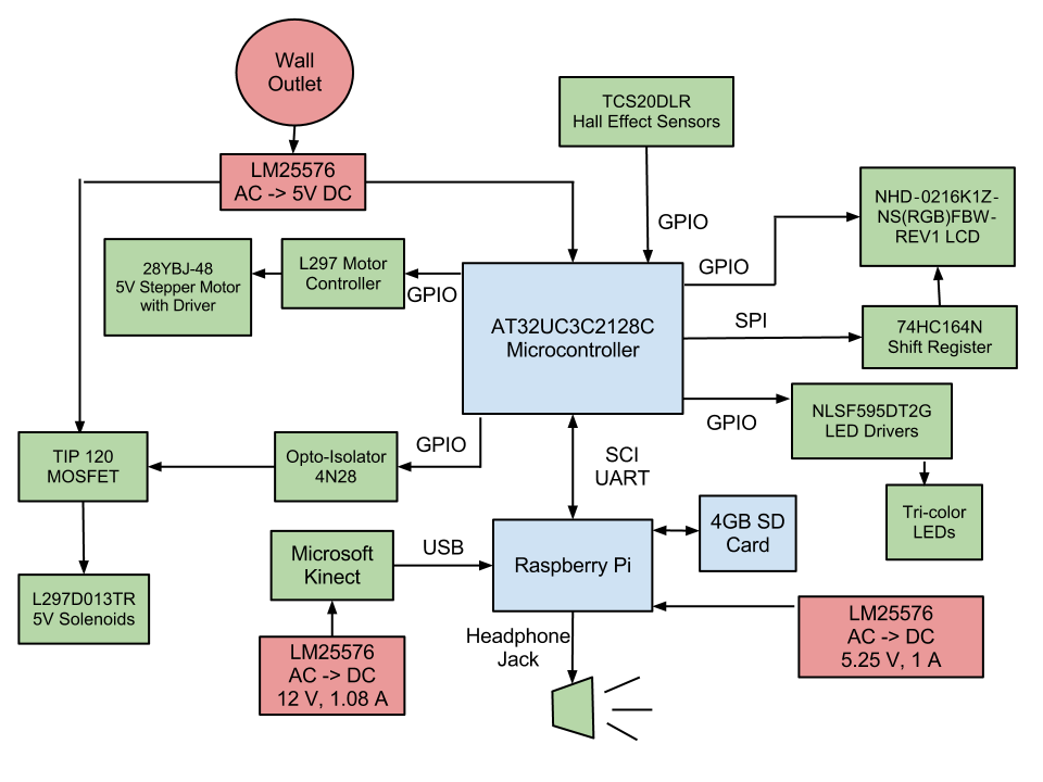
- Met as a team to finished selection of parts and draft majority of HW3. Updated block diagram is shown below:
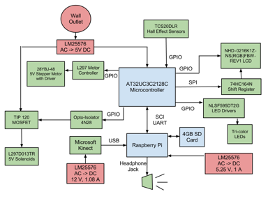
- We currently plan to use numerous LM25576 ICs connected to a 12V DC wall-power supply to provide power to all of the various components in our device. We are not sure if this is the best method for power regulation and distribution, so we'll have to seek advice from the course staff.
- Decided not to package Kinect with device so as to reduce MSRP and allow people to use their own Kinects with it instead. This also allows us to set the cost goal of the device around the current price of an Xbox game.
- Opted to use AT32UC3C2128C instead of 1512C to reduce pin count, number of peripherals, cost, and size of internal memory after receiving feedback from peers.
February 1, 2013 (3 hours)
- Completed HW3.
WEEK 04 SUMMARY
- Accomplishments: Made significant progress on preliminary design. Selected major parts needed. Set up Raspberry Pi.
- Weekly Work Total: 21 hours
- Project Work Total: 39 hours
Week 05
February 3, 2013 (7 hours)
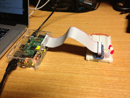
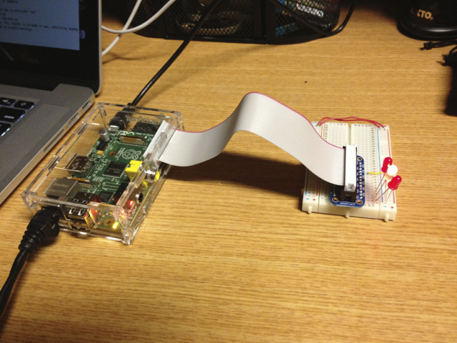
- Experimented with Raspberry Pi. Created simply program utilizing GPIO to blink LEDs:
- Attempted to play MP3 file through analog stereo headphone jack. A major glitch in the sound can be heard at the beginning and end of playback. Web research claims this is due to a power-saving feature in the audio PWM where it is turned on and off before and after playback. This causes a volate spike that is then passed out to the speakers. No fixes are available yet, though I toyed with the idea of creating a script for gapless playback, thus keeping the audio on constantly and preventing the glitch. That idea is still a work in progress.
February 5, 2013 (9 hours)
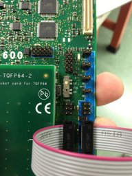
- Consulted with George about various project needs, including power system, chip selections. Also consulted with Ben about availability of breakout boards for chips and emailed Aditya to get Atmel Dev Kit. At Aditya's request, selected Atmel STK-600 dev board with STK600-RCUC3C2-40 routing card and TQFP64 Socket Card for STK600 as needed hardware, totaling about $260.
- Completed initial parts orders. Can be found at links below:
- Made significant updates to parts lists. In particular, replaced previous LED driver with 16-channel PWM driver with selectable output current and serial interface. Should allow for much finer grained control of LED lighting intensities and color blends. Added diffused RGB LEDs to list of parts and adjusted quantities of parts needed to reduce cost. Added MAX3391 logic level converter to interface Raspbery Pi's UART with that of the Atmel 2128C. Updated parts list can be found here. Total cost of this order is $274.05.
- Updated block diagram to reflect design changes and additions. Shown below:
- Looked into using wiringPi modules with Raspberry Pi for GPIO interfacing. This would suggest that we should program our Pi in C since the modules are written in that language, though wrappers exist for every other major language as well. Still, wiringPi's C APIs are very simple and flexible, so my feeling right now is to look into working in C. This will also be consistent with Jackie's work in C/C++ on the Kinect interfacing side.
February 9, 2013 (9 hours)
- Experimented with Raspberry Pi. Successfully managed to do the following:
- Use UART serial pins. Created loopback test to send and receive data serially using UART.
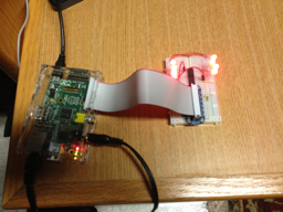
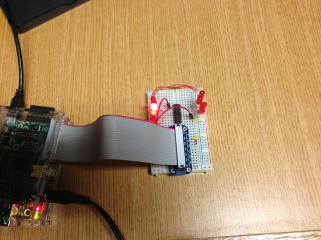
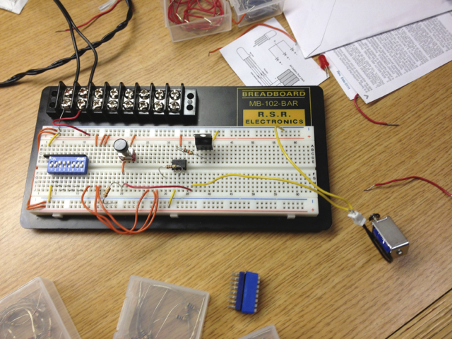
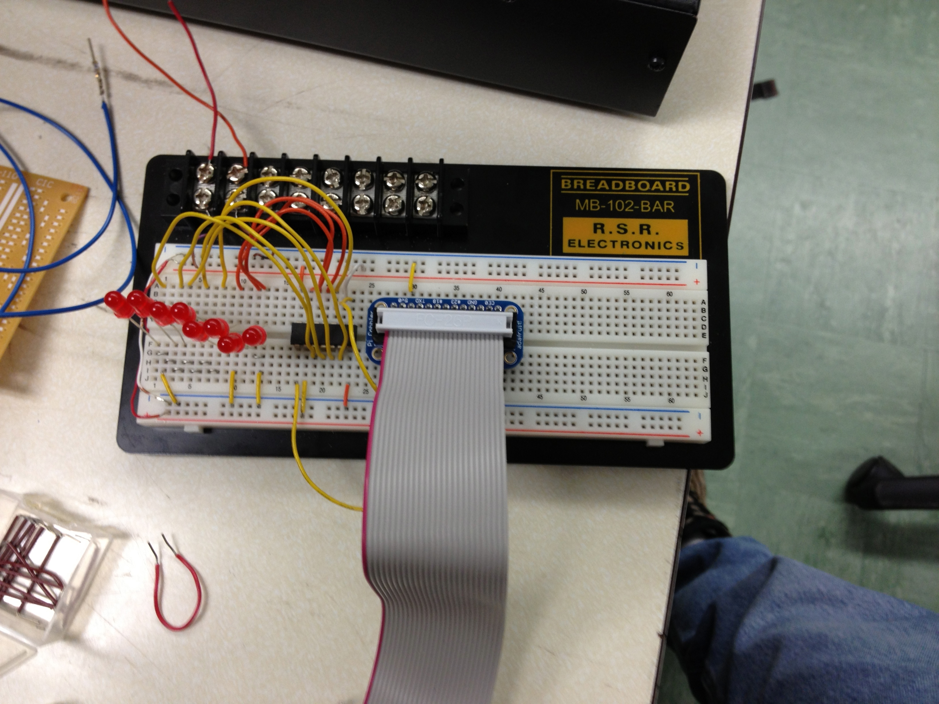
- Drive a 74HC164 shift register to which several LEDs are connected. Wrote a script to test this using both "bit-banging" and actually using the RPi's SPI pins. Images of the SPI driving the LEDs are shown below:

- Play audio without glitching at the beginning and end. Apparently, whatever patch I ran on the system the other day worked for WAV files; it just doesn't work for MP3s. In light of this, we will use WAV files for game music instead of MP3 files.
- Installed wiringPi modules on R-Pi for use later in C code.
- Created personalized notebook CSS file, allowing creation of lists inside boxes. Reorganized entire lab notebook to fit new style.
WEEK 05 SUMMARY
- Accomplishments: Experimented with Raspberry Pi. Wrote scripts testing serial communication via UART, audio playback over headphone jack, and serial LED driving. Updated parts list and submitted first set of parts orders. Created personalized lab notebook CSS and reorganized lab notebook.
- Weekly Work Total: 25 hours
- Project Work Total: 64 hours
Week 06
February 12, 2013 (10 hours)
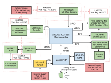
- Updated block diagram.
- Removed power-related blocks as they were just cluttering up the diagram.
- Added pin numbers and determined number and type of each peripheral pin needed from microcontroller.
- Updated block diagram is shown below:

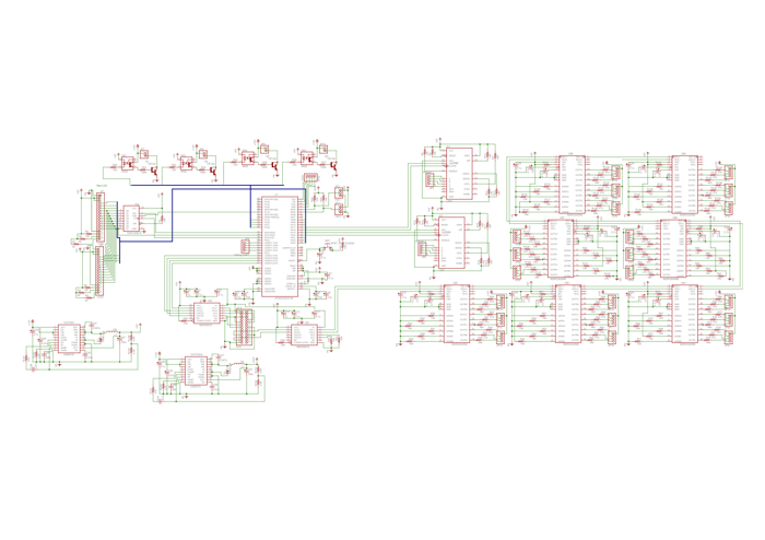
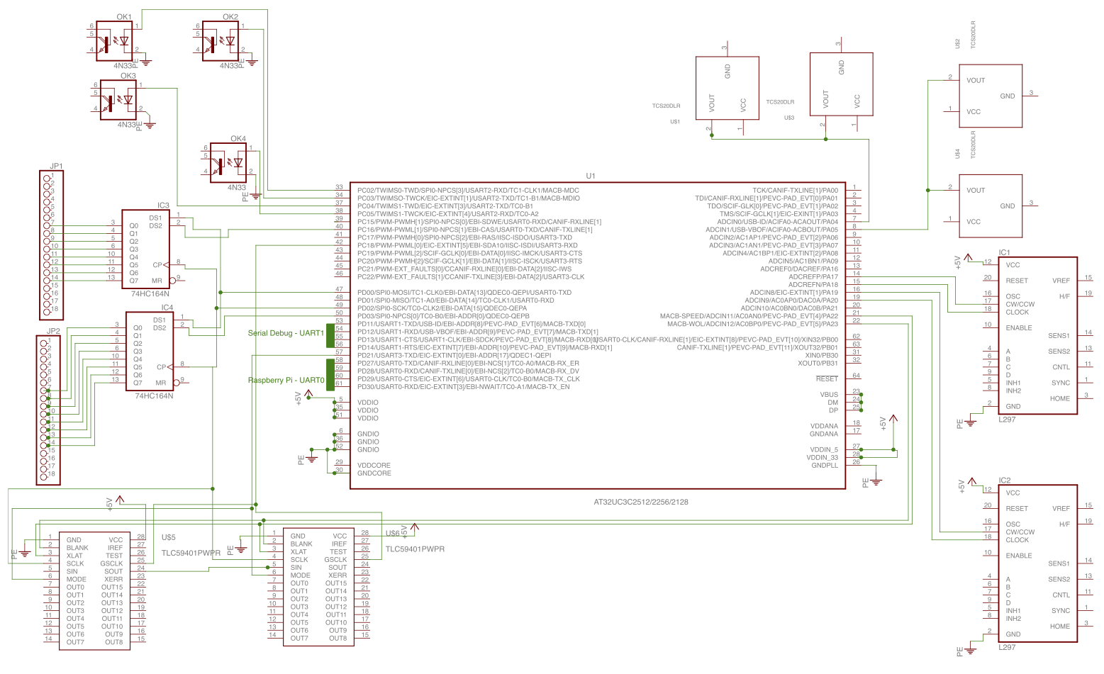
- Worked on preliminary Eagle schematic.
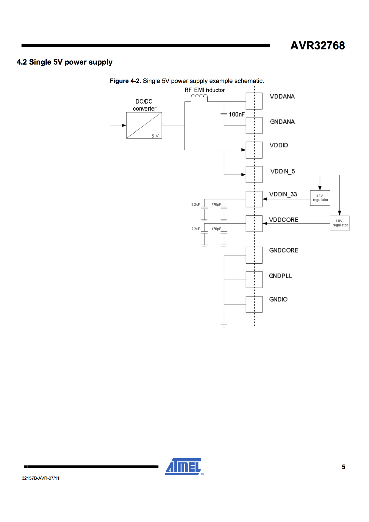
- Read through data sheets of all parts to determine passive component needs. The Atmel microcontroller documentation has a sample schematic (found here) for wiring up its power supply, though I am not sure what value to use for the "RF EMI Inductor" and will have to consult someone more knowledgeable. Passive components are also needed for the MAX3391 logic level translators, the servo motor optical-isolation and power circuits using a 4N33 and TIP120, and the LM25576 voltage converters used for the power supply voltage regulation.
- While reading through datasheets to determine passive compone passive component needs, discovered that the LED controller we chose and already ordered has an internal counter used for controlling the greyscale brightness of the connected LEDs that must be reset when the counter value exceeds 4096. The chip also requires an external PWM signal for proper operation. Other than toggling a GPIO pin and counting the number of times that is done, I can't think of a good way to operate this part effectively for our purposes. We may need to look into using a different controller.
- Mark assisted me by finding many of the parts in existing Eagle standard and vendor libraries as well as creating of many of the new parts we couldn't find, such as the TCS20DLR Hall-Effect Sensors and the TLC59401 LED Drivers.
- Edited symbol pins on the 74H164E in Eagle to match the pin names of the package we are using from Texas Instruments datasheet, found here.
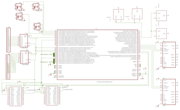
- Updated schematic is shown below:
- Created presentation slides for TCSP #4, viewable here.
February 13, 2013 (6 hours)
- Visited the EE Parts Room and picked up several TIP120 components for use in our project.
- Met with Josh from Team 3.
He offered an alternative part (datasheet here) that is free-running, requires no external PWM, and has built-in multiplexing capability for numerous chips. It also controls LEDs based on the input of a fade duration and max power setting, thus allowing for easily adjustable and automated fading effects. The only drawback is that it only powers 3 LEDs at a time (instead of the 5 the TLC59401 can), but I felt that the benefits were enough that I ordered 10 from Mouser to replace the TLC59401.
- He donated several tiny magnets that we can mount in the fists of our robot for hit detection. Along with that, he loaned our team a prototyping board that has a few of the Hall-effect sensors we chose mounted to it for proof-of-concept and testing purposes. We plan to use this to test the distance at which a "hit" is registered.
Further developed preliminary schematic.
- Completed schematic wiring of the LCD header and connecting 74HC164E shift register. Used 130 ohm resistor for the red LED backlight current-limiting resistor and 82 ohm resistors for the blue and green ones.
- With Mark's assistance, completed passive component selection and wiring of the L297 stepper motor controller and the 4N33/TIP120 solenoid power and control circuitry. Selected a 220 ohm current-limiting resistor for the output of the 4N33 diode pin and a 100 kilo-ohm resistor for the 4N33/TIP120 connection.
- Mark again helped out by creating parts for the MAX3391E logic level translator and the new W2RF004RM LED driver.
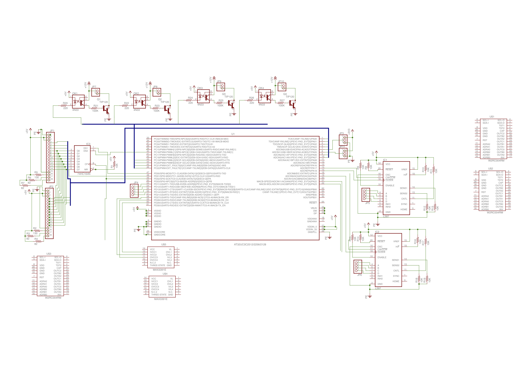
- Updated schematic shown below:
February 14, 2013 (14 hours)
- Decided to use the Raspberry Pi instead of the microcontroller to communicate with LED drivers via SPI. As it stands right now, the synchronization between the lights and sound will most likely be off as the microcontroller will not have an ability to sense when to change lighting effects relative to the song position. Combine this with the fact that our two computational devices are communicating asynchronously via UART protocol, and it just doesn't make sense to separate the audio and the lighting systems. This also means we either must run the new LED driver chips at 3.3V or use a logic level translator between the drivers and the R-Pi. Duncan says he will look into the changes in the passive component values of the power supply voltage converters needed to support this.
- Visited the EE Parts Room to pick up some 4N33 optical-isolators.
- Completed Preliminary Schematic.
- Created symbol, package, and part for LM25576 Switching Regulator. Updated symbol on the 174HC164 part we chose to show VCC and GND pins.
- Researched how to assign functions (eg: pwr, in, out) to pins on part symbols in Eagle. Updated all pins on all custom parts we've created so far to reflect this, which should aid in checking the wiring of the schematic via ERC and in PCB development.
- Changed wiring of control signals of LEDs to be driven by the Raspberry Pi instead of the microcontroller. Also decided to use additional MAX3391 logic level translator between the R-Pi and LED controllers and run the LED controllers on 5V to avoid having to recalculate passive component values for the 3.3V voltage regulator.
- Included 7 LED controllers in final design, which should support up to 21 LEDs. My intention with this is to have 1 controller each dedicated to the 3 LEDs mounted next to each of the 2 LCD screens for use as a positioning or status indicator for the Kinect. That leaves 5 controllers, or 15 LEDs, left for general effect lighting. Right now, I think the idea is to mount at least three of them per side of the arena on the edges of the top side of the arena surface. The remaining chip will be used then only if we need it.
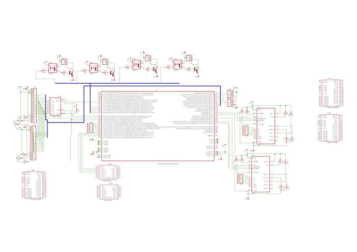
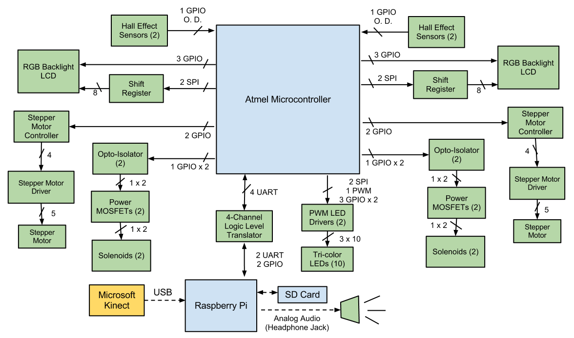
- Updated block diagram reflecting recent design decisions is shown below:
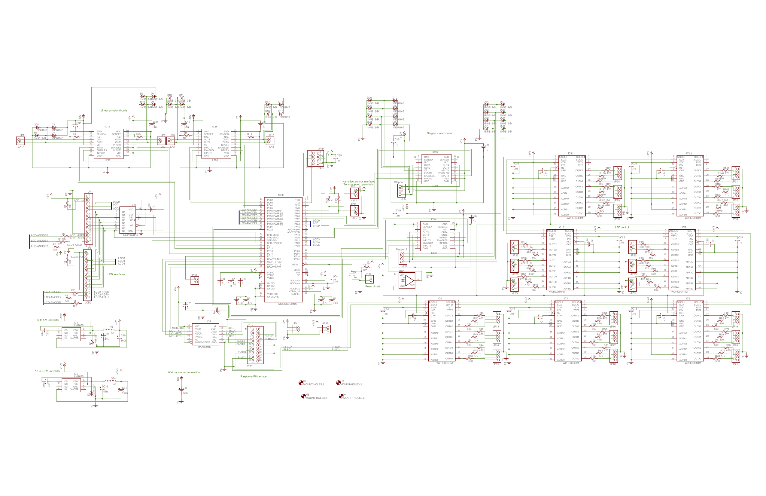
- Finished Preliminary Schematic is shown below:
- Completed Hardware Design Narrative (available here).
WEEK 06 SUMMARY
- Accomplishments: Completed preliminary schematic and hardware design narrative. Identified and selected all passive components and values. Selected and ordered new LED controllers.
- Weekly Work Total: 30 hours
- Project Work Total: 94 hours
Week 07
February 17, 2013 (4 hours)
- Began creating LED control library. Currently all it can do is initialize the Raspberry Pi's SPI, form a 40-bit commmand, and output it via the SPI. The W2RF004RM LED Controller's command format, which I used in creating the command formatter, can be found on page 4 of this datasheet in the "Communication Specifictions" section.
- Researched creation of makefiles extensively to help with code organization, etc. of programs on the Raspberry Pi. Since most of our programs will be in C, it was useful to figure out how to compile and run various tests from a single Makefile, as well as compile the libraries and scripts we will eventually use for the final project operations.
February 18, 2013 (6 hours)
- Visited the EE Parts Room to get some pushbuttons.
- Reorganized documents on website and updated links as needed.
- Researched audio playback options for C programs, but with no good results.
- Considered using PortAudio (weblink here) since it is compatible with ALSA linux audio manager, but the API seems overly complicated with too much overhead for what we need to be able to do with simple playback and stop interrupts.
- Considered using C system calls to control the ALSA audio player since I've had success playing WAV files from the command-line using it. This involves tricky process forking, pipeing, and killing however that also seems extreme for our needs, but it remains as a fallback idea.
- Researched audio playback options for Python programs, with much greater success.
- Recalled using TkSnack library for audio playback in Python when I was a TA for ECE364. Found the libraries stored in my archived folders and extracted them for possible use.
- Will also look into using PyGame audio playback library as I recall some students had issues with TkSnack since it has been somewhat abandoned.
- Opted to switch to using Python as the primary language on the Raspberry Pi rather than C. Reasons include:
- Python has less coding overhead than C, as well as greater support for object-oriented constructs.
- Based on my research, Python also has greater library support for audio playback than C does, and those libraries have much simpler APIs.
- A Python wrapper already exists for wiringPi, the Raspberry Pi low-level peripheral library we have chosen to use and with which I am familiar.
- Even though Jackie's Kinect interfacing code is written in C++, my research into Unix pipes leads me to believe our code should be able to communicate either by pipe or Unix FIFO, regardless of language implementation.
- Created an initial flowchart for main Python script which will be run at startup on the Raspberry Pi. The intent is for this script to launch the Kinect interfacing C++ code and handle any inter-process communication needs. It will also communicate with the microcontroller via UART and possibly handle the LED control and audio playback. The latter two functions might need to be delegated to separate scripts, in which case they will be launched along with the Kinect program. A general flowchart outlining this concept is shown below:

February 19, 2013 (3 hours)
- Installed Atmel Studio 6 for microcontroller development. This required creation of a virtual machine for Windows 7 first on my system, which took quite a while to set up and get fully running.
- Setup folders and Git infrastructure for Python scripts on the Raspberry Pi.
February 20, 2013 (3 hours)
- Tested new parts that came in today.
- Tested tri-color LED to identify whether or not external resistors were needed. The LED burned out and smoked up the room when powered with no resistors connected, so it is safe to say that externals are indeed needed. LEDs were very bright at suggested values on included datasheet, so I chose to use 560/470/470 ohm current-limiting resistors for the red, green, and blue pins respectively.
- Tested solenoid independent of, then connected to its power circuit. Test circuit is shown below:
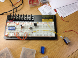
- Attempted to actuate robot "punch" motion using the solenoid.
- The latter test was unsuccessful, likely due to either the fact that we were testing at only 5V rather than the 12V we intend to ultimately use or that the solenoid we have is just too weak to push the punching pin on the robot. We will test using a 12V supply tomorrow.
- In anticipation of the latter case, however, Mark and I looked into replacement solenoid options. We believe this one would probably be the best replacement. It has a 12mm stroke with 2.87 lbs of pushing force, which should be exactly what we need. The drawbacks are that it is four times more expensive than the previous solenoid model we chose, it requires a 24V power supply, and it is much heavier. We may need to re-evaluate our PSSCs and eliminate robot dodging from our project if we decide to use these solenoids as they might be too heavy to move laterally with the robot.
February 22, 2013 (2 hours)
- Picked up Atmel STK600 dev board and starter kit from Aditya. Also got breakout boards and a large breadboard for prototyping.
- Rewrote PSSCs with George's advice. They are now:
- An ability to power and control electric motors.
- An ability to detect a "hit" on an opponent.
- An ability to track player movements with a Microsoft Kinect.
- An ability to provide player feedback using sounds, LEDs, and game information via LCDs.
- An ability to play in either single or dual-player mode.
WEEK 07 SUMMARY
- Accomplishments: Began development of Raspberry Pi software libraries and set up my computer to use Atmel Studio for programming the microcontroller. Researched options for audio playback in both C and Python extensively, and decided to use Python for programming Raspberry Pi software. Received and gathered many of the components and equipment needed to begin prototyping and testing design.
- Weekly Work Total: 18 hours
- Project Work Total: 112 hours
Week 08
February 24, 2013 (4 hours)
- Unpacked dev board and set up with microcontroller. Could not get board to run microcontroller at the desired 5V. After significant online research, I determined that I had to cut two traces marked on the board's routing card, which immediately fixed the problem.
- Relocated many components from home to the lab and organized on the lab bench.
February 26, 2013 (3 hours)
- Discovered the Atmel Software Framework documentation website while doing general research. Previously we had significant issues in trying to figure out anything about the API for our microcontroller. Link is here for future reference.
- Met as a team to discuss project status. Created project schedule for remaining weeks of semester in preparation for Design Review.
- Successfully created Python test scripts of several Raspberry Pi features.
- Used PyGame module to successfully playback .WAV audio files. PyGame has significant support and documentation (link here) for playback of these types of audio files. The modules of interest are the pygame.mixer and pygame.mixer.music ones, which allow interfacing with the system audio drivers and management of sound playback, pausing, fades, etc. respectively. Any scripts run using this module must be run as a super-user however in order for the scripts to be able to access the system audio drivers. I will look into adjusting a config file to enable plain user access to these drivers.
- Used both spidev and wiringpi modules to successfully toggle LEDs using the Pi's SPI and a 74*164 shift register. The wiringpi version of the script doesn't actually use the SPI; it performs automated "bit-banging" and requires initialization of the GPIO pins as outputs first. It also does not have an adjustable max SPI clock speed, which the spidev module does. The spidev module does use the device SPI, but wiringpi apparently modifies some system config file that prevents spidev from working if wiringpi is used beforehand. Further tests are needed to determine which module will ultimately best suit our needs.
February 27, 2013 (4 hours)
- Received new breakout boards with correct pitch from Aditya. Soldered headers on to them for practice with soldering.
- Completed true test of Raspberry Pi SPI using spidev module in Python.
- Added a call to wiringpi initializations as well to toggle an additional LED as a test to see if the two modules get along well. No issues were observed.
- Decided to use spidev module over wiringpi since it has an adjustable max SPI clock speed, works well with the other modules we are using, and requires minimal initialization.
- Updated pygame music test to use pause() and unpause() methods. I plan to eventually also test out the queue functions and try queueing up silence to prevent the PCM module from shutting down and causing the annoying audio glitches for which the Pi has become infamous.
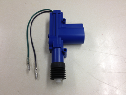
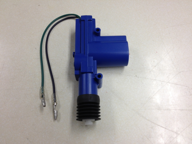
- Tested out new linear actuator with Mark. Discovered that The actuator has sufficient force to push the robot's punching pins and create the punching motion we want. It is also light-weight, meaning we can still have the robots dodge punches, and it is low cost (about $5 per motor). Mark ordered several more for use in the project. A photo of it is shown below:
February 28, 2013 (6 hour)
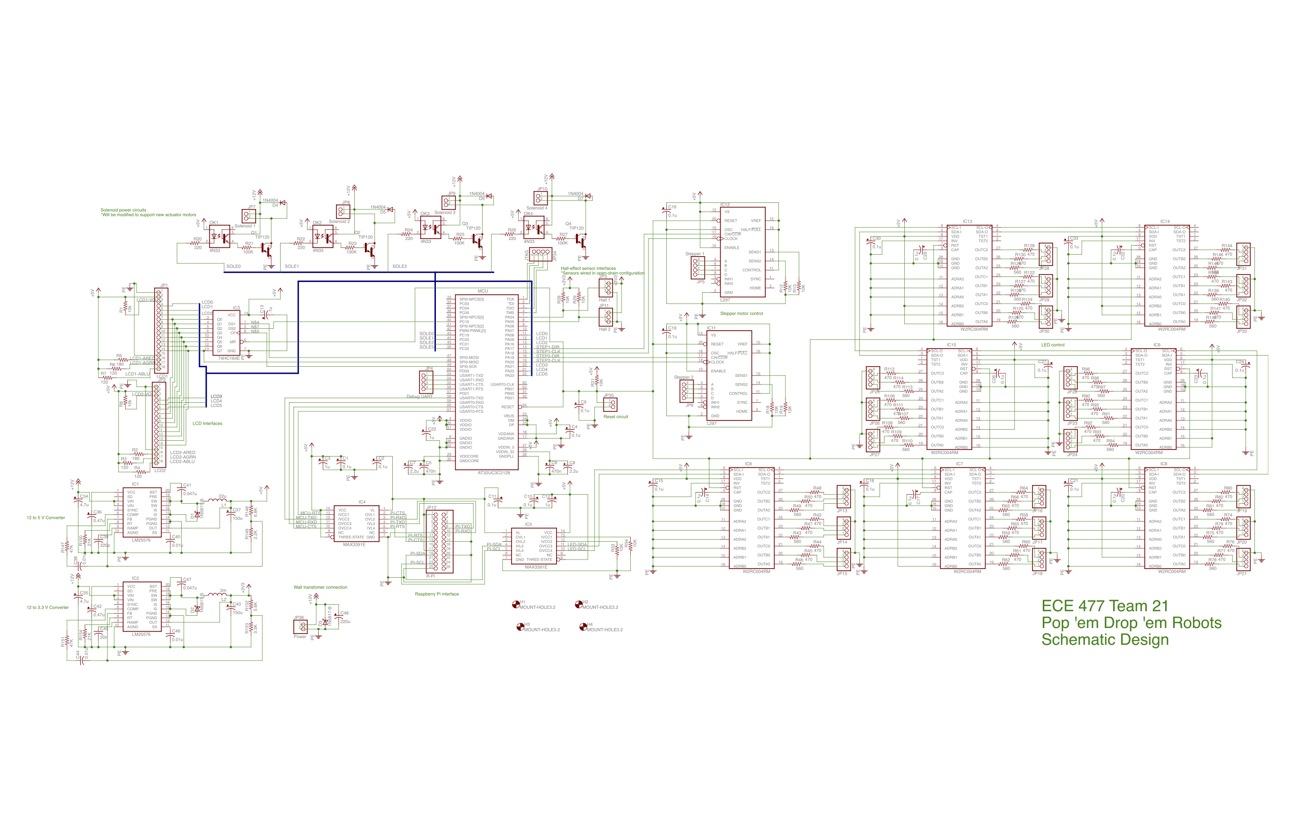
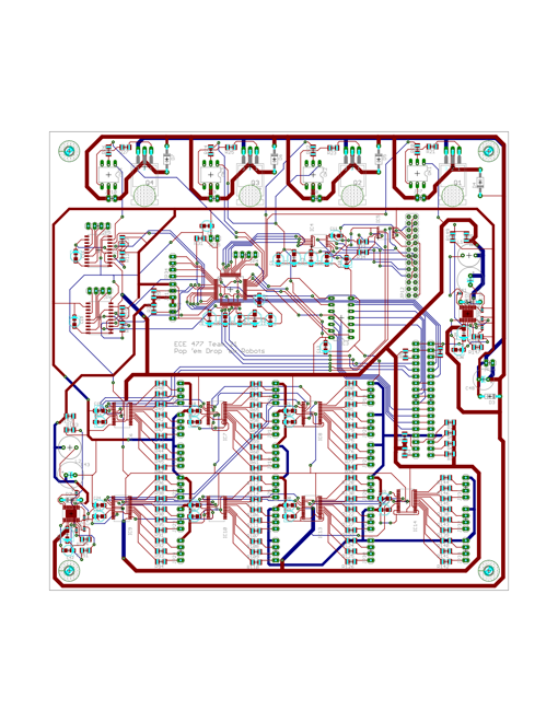
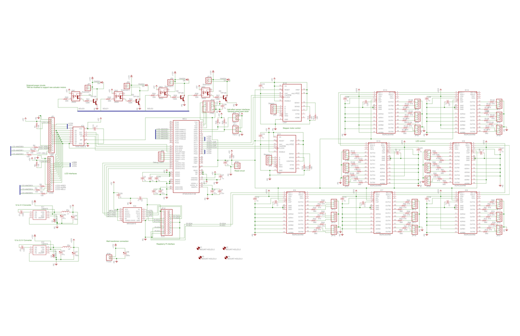
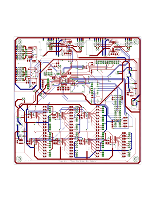
- Updated schematic and PCB for Design Review. The new power circuitry for the linear actuators has not yet been designed, and the JTAG and spare UART interfaces need to be reexamined at some point. Everything else has been finalized, though most components and subsystems still remain untested. Both schematic and PCB are shown below:
- Completed Schematic/Theory of Operation slides of Design Review Presentation. (Presentation link here)
March 1, 2013 (1 hour)
- Completed Design Review presentation and received plenty of feedback. Suggested changes include:
- Reduce size and complexity of power supply circuitry.
- Reduce number and size of bypass capacitors in the circuit. We can combine several of them and reduce our parts count. Many weren't close enough to their respective IC pins on the PCB that they would be effective anyway.
- Change operating voltage of LED controllers to 3.3V and then remove the unnecessary logic-level translator from Raspbery Pi SPI signals.
- Change pull-up voltage on Hall-effect sensor network to 5V. This was an error in the schematic that would have led to the input pin continuously sourcing current to the sensors.
- Add H-bridges to control the new linear actuators we bought. This should enable us to control the push and pull motion effectively.
- Connect a microcontroller PWM channel to each of the LCD backlight anodes to enable color control. Previously, we had all three anodes tied to power, which would have simply resulted in the backlight always being white and defeating the purpose of using an RGB-backlit LCD.
March 3, 2013 (1 hour)
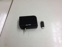
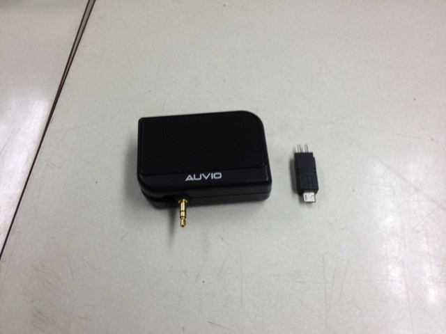
- Purchased a speaker and power connector for the Raspberry Pi. We hope to be able to use the connector to run the Pi from the main power supply of the project, reducing the number of wall plugs to just one. Photo of both items is shown below:
- Ported much of the C code I had already written for the led_control library into Python. I made the library into a rough object as well so that we can utilize some of Python's object-oriented capabilities. More functionality still needs to be added, but for now the library can theoretically parse and send commands to an LED controller.
WEEK 08 SUMMARY
- Accomplishments: Began experimenting with microcontroller. Completed proof-of-concept testing of Raspberry Pi peripherals and can begin writing libraries. Received proper breakout boards and began prototyping design. Solved robot punching issue by using a linear actuator instead of a solenoid.
- Weekly Work Total: 19 hours
- Project Work Total: 131 hours
Week 09
March 4, 2013 (5 hours)
- Worked on getting microcontroller to operate with no real success.
- I spoke with Josh from Team 3. He has had success getting their Atmel device to work, but he was unable to figure anything out beyond what I already knew. He did show me how to access the Atmel Software Framework from within Atmel Studio, as well as how to load library modules like sysclk, ioport, gpio, delay, etc. I believe this will prove very useful later on.
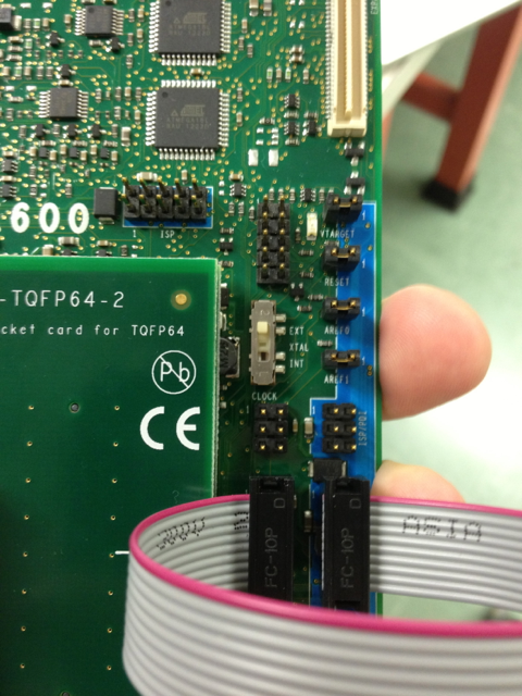
- Searched the ASF documentation for the aforementioned libraries and for our development board, looking for reasons the microcontroller might not be working. The documentation suggests to me that the problem is actually with the clock. (Link to STK600 Clock Settings reference here) To use the STK600 board's clock generator, the clock select switch must be set to EXT. To use an external oscillator module, it must be set to INT, which disconnects the board's generator and routes the oscillator signal from a header pin to the XIN pin on the microcontroller. I suspect from this that the issue is somewhere in either the wiring or the software initializations.
- Photo of the STK600 clock select switch shown below for reference:
March 5, 2013 (6 hours)
- Began writing new functionality in led_control_lib of Raspberry Pi to control LEDs in patterns. It might be easiest to put state variables into the ledControl object that represent the current status of all LEDs being controlled by that object. Then groups of LEDs could also be created for effects like chasing, toggling, etc.
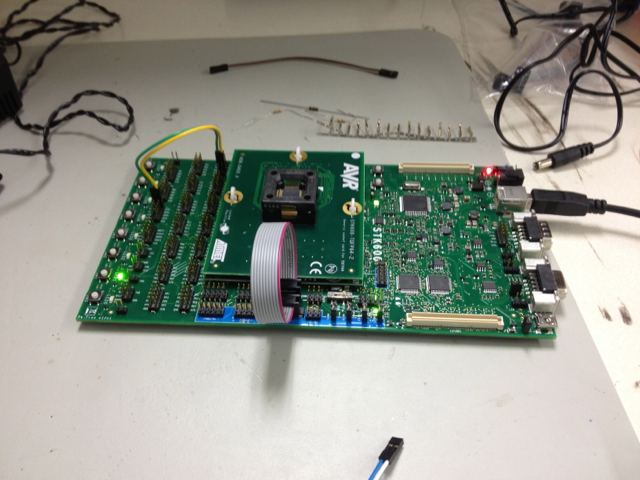
- Managed to get the microcontroller working for the first time. It successfully blinks two LEDs in alternating pattern using both an external oscillator and the STK600 adjustable clock generator. Photo shown below:

Some notes on how this was accomplished:
- When creating the project for the tests, UserBoard UC3 C0/C1/C2 was used instead of the AtmelBoard STK600 - AT32UC3C0512C. Using the latter resulted in some autogenerated code that did not work when we set the current device in Atmel Studio to the 2128C (various pins were mapped that did not exist on the 2128C, parameters names were different, etc.). This was in part due to the fact that the appropriate header files only exist for the UC3C0 or 144-pin packages, not the UC3C2 or 64-pin ones that we have, so various pins were getting mapped that didn't exist on our microcontroller.
- To setup the system clock using the sysclk library, the parameters BOARD_OSC0_HZ, BOARD_OSC0_IS_XTAL, and BOARD_OSC0_STARUP_US were defined in conf_board.h to match the desired clock configuration in the sysclk library. The first parameter is set to the desired clock speed, the second is always set to true, and a suggested value of 1100 works well for the third. In conf_clock.h, uncommenting the CONFIG_SYSCLK_SOURCE line which sets it to SYSCLK_SRC_PLL0 allows the STK600 clock select switch to determine the clock source (EXT for board clock generator, INT for an external oscillator module).
- Only the ioport, sysclk, and delay modules were used in the creation of the blink test. The ioport_set_pin_dir function and the ioport_set_pin_level function were all that were needed to toggle GPIO pins. The delay_ms function was used from the delay library to add an automatically adjusted CPU wait time based on the clock frequency.
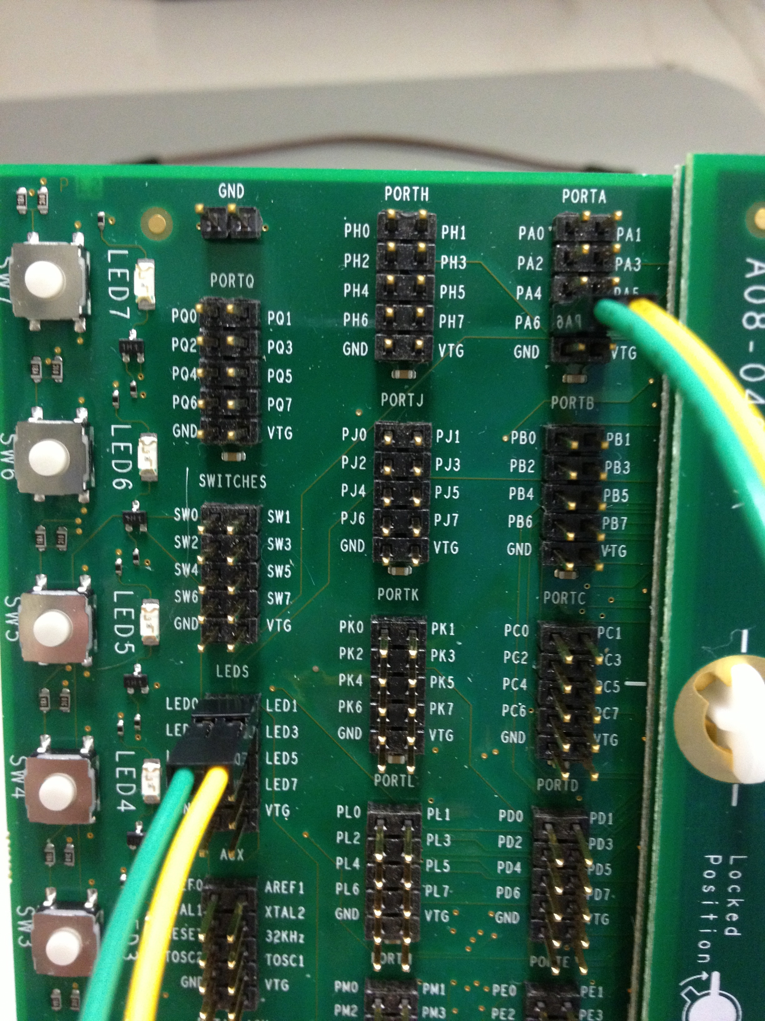
- The PA06 and PA07 header pins, mapped to microctonroller pins PA6 and PA7 respectively, were connected to the LED0 and LED1 header pins on the STK600. The STK600/microcontroller pin routing can be found here. Wiring shown below:

- Brainstormed new ideas for stepper motors with Mark since the ordered ones never came in. We think it might be easiest to mount the stepper motor in line with the feet of the robot with the actuators hanging below the stepper motor so that the motor is closer to the center of gravity of the moveable assembly. This would also change from a translational movement when the robots dodge to a rotational one that mirrors more accurately the user's movement with respect to the Kinect.
- Fixed several minor changes on schematic based on Design Review feedback.
- Rewired LCD shift register chip enable to SPI-NPCS[0] instead of a GPIO pin to allow SPI to use it if desired.
- Reduced Hall-effect pull-up resistors to 1K from 10K per Dr. Meyer's suggestion.
- Instructed Duncan on what to modify to change operating volatage of LED controllers to 3.3V and remove unnecessary logic-level translator.
March 6, 2013 (6 hours)
- Researched and worked on test code for using SPI Master library and interfacing with LCD.
- Researched and worked on test code for using UART.
- Modified schematic based on Design Review suggestions.
- Updated JTAG header to be correct 2x5 pins (instead of 1x4).
- Changed pull-up voltage on Hall-effect sensor network to 5V instead of 3.3V. This was brought to our attention as a schematic error during the Design Review.
- Changed LCD backlight anode pins to be connected to PWM pins on the microcontroller. This enables us to control the color and intensity of the backlight. Substantial rearranging of GPIO pins connections to components was required to accomodate the needed PWM channels.
- Updated schematic shown below:
March 7, 2013 (8 hours)
- Assisted Mark with developing new support circuitry for linear actuators and new stepper motors.
- The drivers chips Duncan had ordered did not meet our needs after all, so we ordered several L298 H-bridges (datasheet here) which can be used to control both the actuators and the new bipolar stepper motors. Each L298 can control either two actuators or one bipolar stepper and requires a total of 4 GPIO pins from the microcontroller.
- Based on lab tests and Mark's calculations, each actuator has a current requirement of about 1A to be effective for our needs. To support this, we had to purchase a much larger power supply (12V, 6A, 72W) and get some 10W power resistors (link here) to limit the current spike.
- Set up Git repositories on GitHub for both Atmel Studio and Eagle projects as a preventative measure in case of disaster.
- Worked with Spencer from Team 3 to get Raspberry Pi set up in lab for testing.
- Up until now I had been unable to test peripherals with the Pi from anywhere but home due to an inability to SSH into the Pi from behind Purdue's network. Spencer showed me how to find the public IP address in the boot messages and suggested I purchase an HDMI to DVI adapter cable so I can view these messages when we first boot the Pi in lab.
- Spencer also pointed out that we need to find a way to safely shutdown the Pi without just cutting the power or else we risk corrupting the Pi's SD card. The implementation of this will required some thought.
- Assisted Duncan with finishing up schematic and PCB design for submission.
- Added 5V header connection for Raspberry Pi power connector and 3.3V header connection for speaker power.
- The extra pins needed for the L298s forced us to give up having a serial port for debugging and left only 2 spare GPIO pins on the microcontroller. We routed these to a header for potential use later.
Jackie checked the microcontroller pins in the schematic to make sure they were all accurate. We fixed one issue where two of the pins we had assigned to GPIO were for reference voltage inputs and were not marked as such on the part symbol we were using.
- Final submitted schematic and PCB design shown below:
Attempted to test SPI and LCD interfacing of microcontroller. Made a number of discoveries:
- The STK600 doesn't seem to be able to supply enough current to drive the LCD, even with an external supply attached. I believe this issue might be fixed if I use a separate power supply connected to the breadboard.
- The board reacted very negatively to SPI initializations by blinking the status LED red. According to the STK600 documentation, this usually indicates a short circuit. I inspected the board, routing card, socket card, swapped out the microcontroller for a new one, and dissassembled and reassembled the entire circuit, but nothing affected the LED. In the end I commented out some IOPORT lines, wrote to the microcontroller, uncommented them, and rewrote, and everything was fine. This issue needs more investigation to determine the root cause, but I suspect it is software related.
March 8, 2013 (2 hours)
- Completed Schematic/PCB checkoff and parts acquisition.
- Further attempted to test SPI.
- Removed LCD and attempted just to use SPI to drive shift register connected to LEDs. This was also unsuccessful.
- Connected SPI pins to LEDs and toggled via GPIO. This was actually successful, which leads me to believe there are issues with the SPI initializations.
- Possibly fixed the issue with the board indicating a short circuit. I performed a firmware update when it started acting up again. This appears to have solved the issue.
WEEK 09 SUMMARY
- Accomplishments: Programmed microcontroller for the first time with LED blink test. Researched and wrote code for using microcontroller SPI and UART. Completed and submitted final block diagram, schematic, and PCB design for fabrication.
- Weekly Work Total: 27 hours
- Project Work Total: 158 hours
Week 10
WEEK 10 SUMMARY
- Accomplishments: (None - Spring Break)
- Weekly Work Total: 0 hours
- Project Work Total: 158 hours
Week 11
March 19, 2013 (4 hours)
- Attempted to get Kinect software installed on Raspberry Pi, with limited success. Ultimately followed installation procedures here to install OpenNI and SensorKinect software successfully. Still remains to be tested to see if it actually works.
March 21, 2013 (6 hours)
- Successfully managed to get microcontroller SPI working for the first time. Image of SPI operating connected to 74*164 shift register with LEDs shown below:
Some notes on how this was accomplished:
- The IOPORT module apparently does not allow for muxing of peripherals on microcontroller pins. Instead, I used the functions in the GPIO module, which Josh from Team 3 told me his team had used successfully. The documentation for the GPIO module located here, was much more explicit and helpful than the documentation for IOPORT.
- The SPI master module was initialized following the example here.
- Attempted to get Kinect working on Raspberry Pi with Jackie. The Linux drivers I installed the other night on the Pi are naturally for a different architecture than the ones Jackie was using on her Windows-based laptop. For some reason, this meant that the example code did not install to the same directories as well. Jackie is still working on figuring out how to build her code on the Pi, so we have yet to find any code that can run on the Pi as a result. This needs to be top priority for next week for Jackie and I so that we can be sure things will work as expected.
- Unsuccessfully attempted to get LCD powered up and running. Since the SPI is clearly working as evidenced by the photo above, I suspect something is either wrong with the manner in which the LCD is being powered, the wiring is incorrect, or a bad connection exists somewhere.
March 22, 2013 (2 hours)
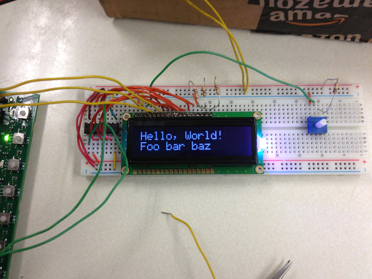
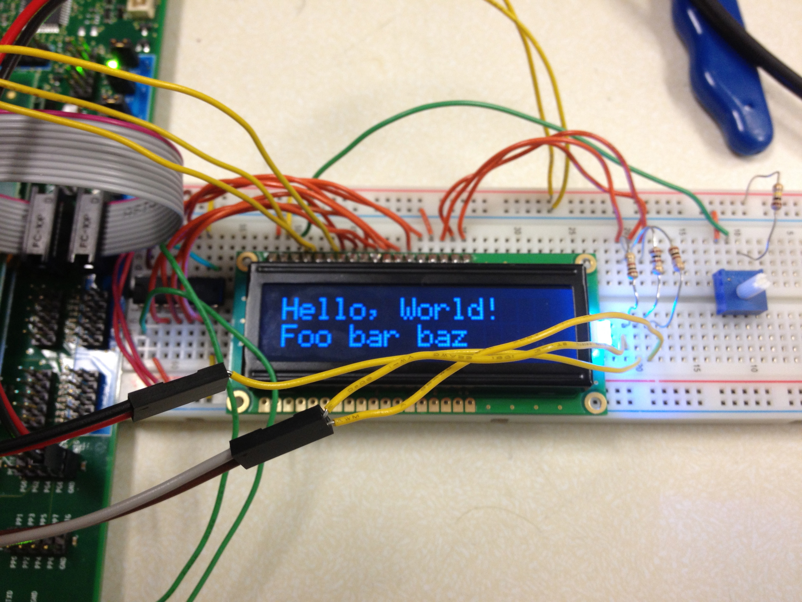
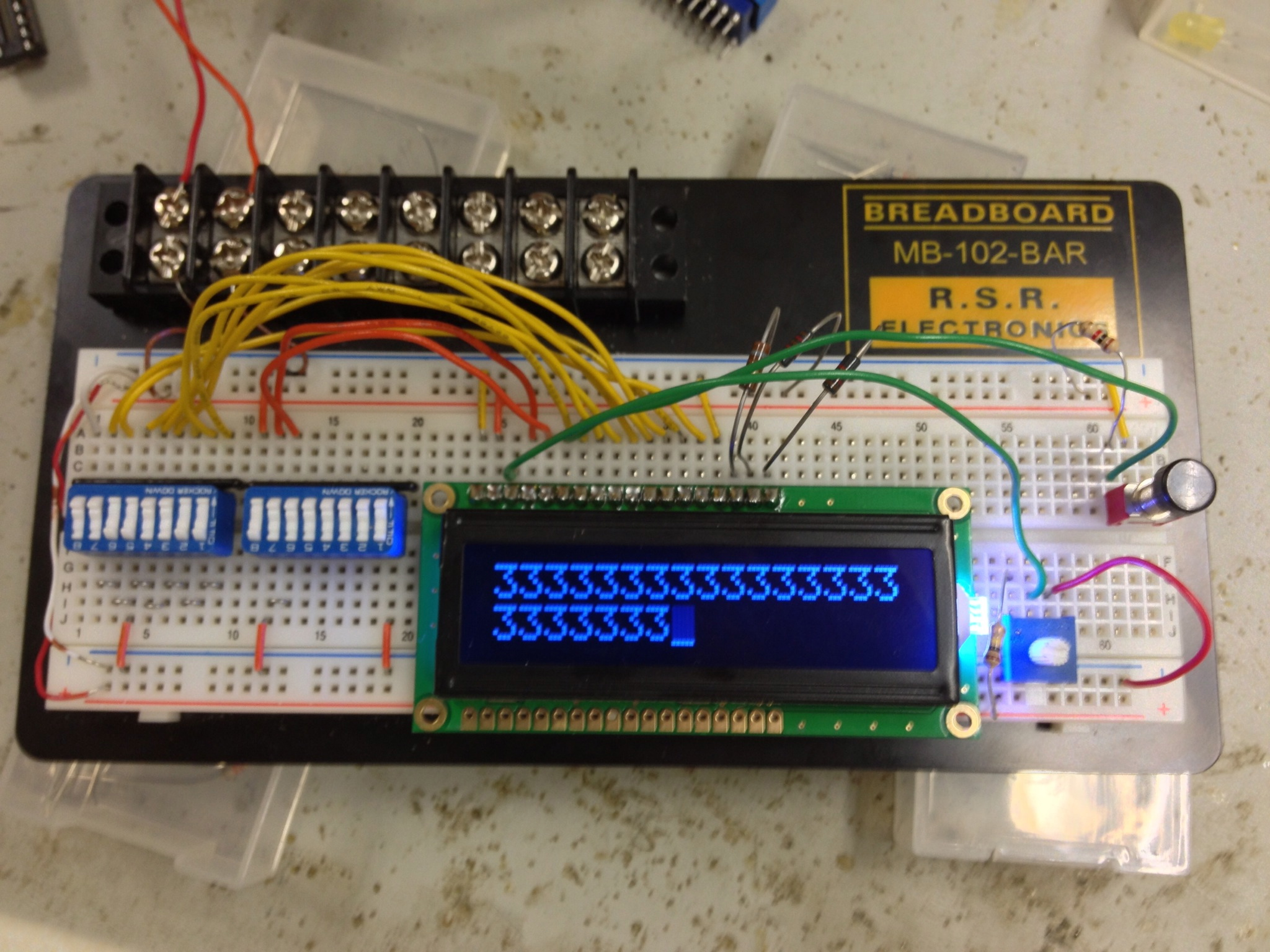
- Successfully managed to get LCD powered and displaying characters. This was accomplished by wiring a separate circuit from the microcontroller in which all inputs to the LCD were connected to DIP switches and operated manually. Image of operation shown below:

Some notes on issues encountered and how they were resolved:
- Power and ground were originally reversed. I misinterpreted the data sheet (link here) description of the pinout, thinking that pin 1 was power and pin 2 was ground. Since they were also designated as Vdd and Vss instead of power and ground, and considering the device lit up even though it was wired backwards, it was several hours before I noticed my mistake.
- The LCD I was testing on seems to be burnt out, possibly because of the previous wiring error. Testing on a second, untouched LCD worked, but applying the same methods to the first one did not yield any results.
- The input voltage to the contrast pin (Vo, or pin 3) must be within the range of 0.5 V to GND in order for text to show up properly on the display. The data sheet sample wiring diagram seemed to suggest that merely wiring a 10K-20K ohm potentiometer connected to power and ground would be sufficient for the device to work. The only problem is, using 5V as the power supply meant that a 1/10 voltage divider was needed to bring the voltage down into the proper range of the contrast pin. Ultimately, this was accomplished by connecting a 100Kohm resistor in series with a 10K potentiometer which was also connected to ground. Connecting the contrast pin of the LCD then to the wiper pin of the potentiometer allowed for proper operation of the device contrast.
- As observed in the photo of the test, the text on the display is primarily blue in color, even though based on the wiring it should be white. This suggests that the values of the current-limiting resistors connected to the LCD backlight might need to be adjusted to increase the red and green LED brightnesses.
WEEK 11 SUMMARY
- Accomplishments: Successfully tested microcontroller SPI and LCD. Changed implementation of GPIO pin manipulation from IOPORT module to GPIO module.
- Weekly Work Total: 12 hours
- Project Work Total: 170 hours
Week 12
March 24, 2013 (6 hours)
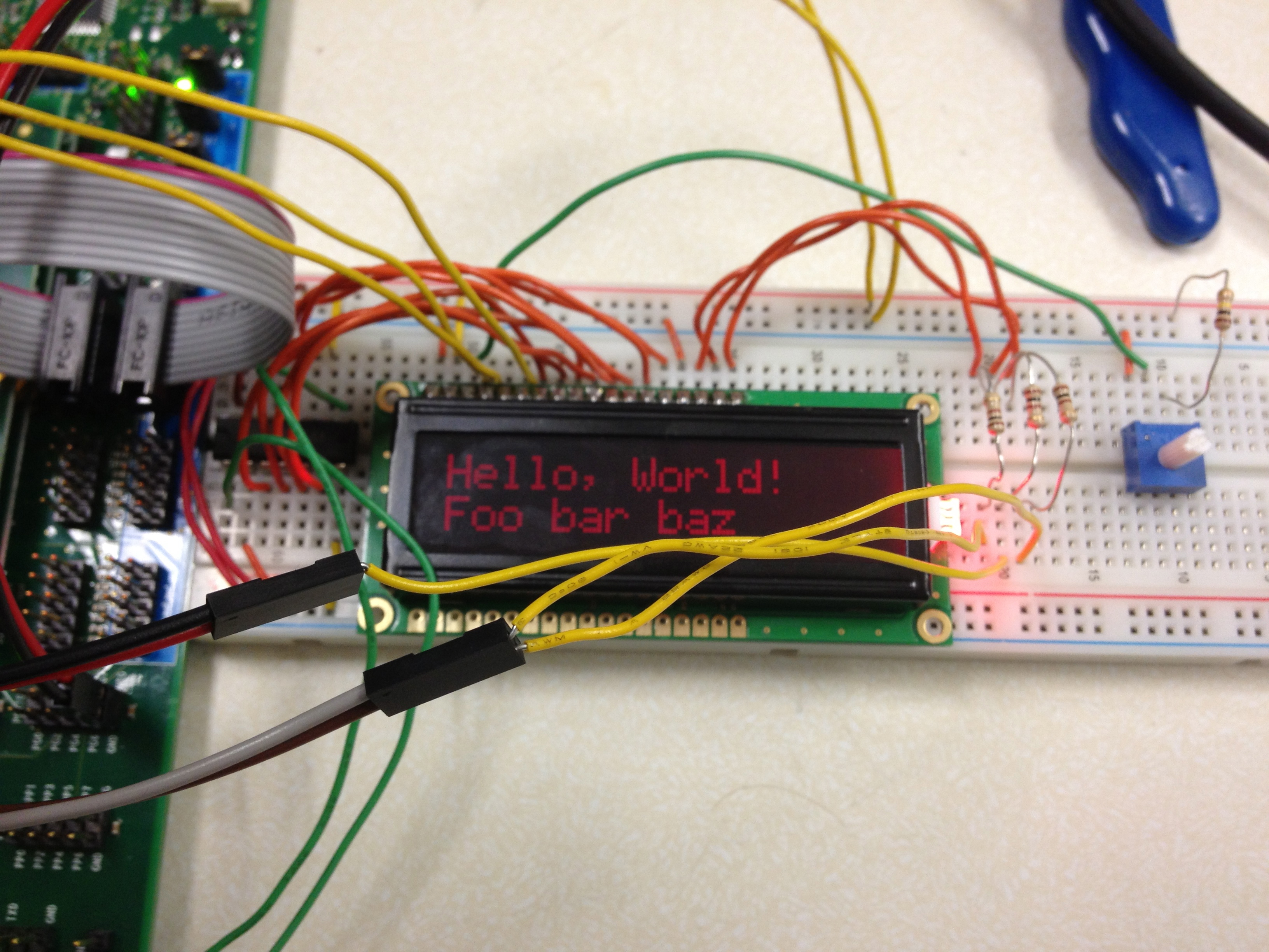
- Adjusted current-limiting resistor values of LCD backlight LEDs to all be 100 ohms, which balanced the individual intensities of each color and created a more true white backlight color than before.
- Successfully controlled LCD using microcontroller. Photo shown below:
- Unsuccessfully attempted to test UART of microcontroller with a simple loopback test. The microcontroller appears to be sending data, but not actually receiving anything yet. It also waits indefinitely to receive data, suggesting perhaps that the UART transmissions are not buffered and that a device must be listening to receive transmitted data. If this is the case, it could be very problematic if we try to use polling as our primary style of programming.
- Researched and began writing code to test PWM module of microcontroller.
- Assisted Jackie with connecting to the Raspberry Pi for testing the Kinect. Also communicated various methods and tactics I had tried as she unsuccessfully attempted to get her Kinect software working.
- Assisted Duncan with testing the MAX3391 logic level translator. Currently, the translator passes signals through properly, but the low-voltage side of the chip is somehow being pulled high from the supplied value of 3.3 V to approximately 4.1 V. When the low side is disconnected from the low supply voltage, the voltage on the supply rail is normal, suggesting that the chip is faulty or wired incorrectly. Swapping the chip and checking the wiring produced no better results. We will have to consult others to determine the issue.
March 27, 2013 (2 hours)
- Researched and discussed alternative options to using the Kinect with Jackie.
- Jackie's research has led her to believe that it is not possible to run the Kinect on the Raspberry Pi. She cannot get the drivers working properly, and her online research suggests that others are having the same issues she is with no working solution. Therefore, we have decided to start seeking alternatives to replace this part of our project.
- Online research shows that at least one book has been written (link here) about interfacing the Kinect with an Arduino. The Arduino Uno uses an ATmega328 microcontroller (datasheet here), which has SPI, UART, and audio capabilities with the addition of an audio "shield." The only problem is that this appears as though it might require more effort to get set up than we have time remaining to complete the project.
- Sid from Team 2 suggested that we look into using WiiMotes with the Raspberry Pi. Widely documented success using this combination can be found online. Receiving WiiMote data with the Pi requires only the addition of a compatible Bluetooth USB dongle. The cwiid module (GitHub repository here) is one software library developed for reading WiiMote data. It is coded in Python and the API appears to be much easier to use than the OpenNI/SensorKinect software Jackie was using previously. Currently, this appears to be our best option, so we will pursue it further.
March 28, 2013 (6 hours)
- Successfully powered LCD RGB-LED backlight using GPIO. Photos of backlight cycling through various colors are shown below:

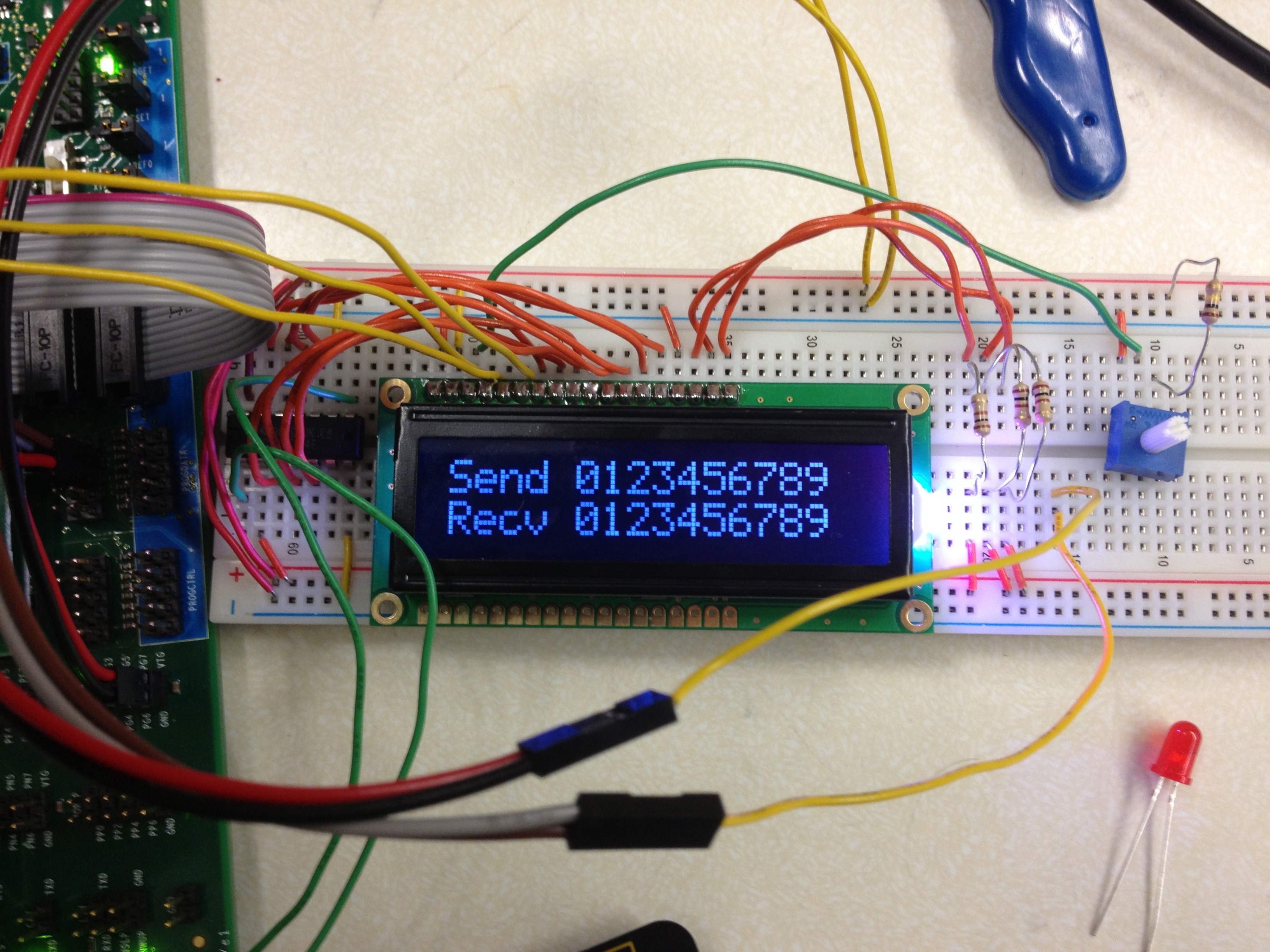
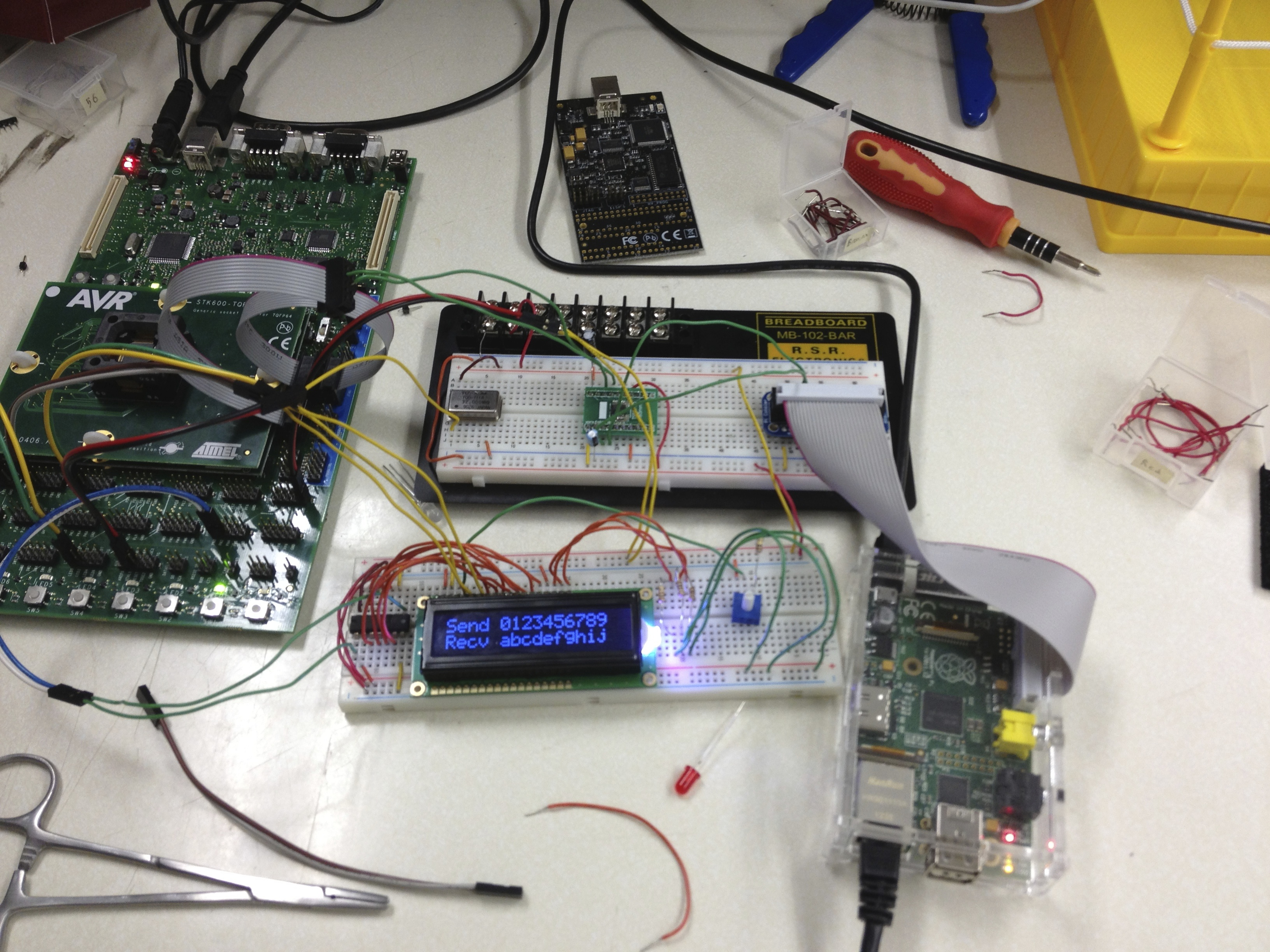
- Successfully transmitted and received characters via UART.
- The pin mapping from the microcontroller pin to the STK600 header was confusing and the STK600 header was not labeled clearly, so I did not have the transmit and receive lines (PDATA3 and PDATA4 respectively) connected properly.
- Photo of UART send and receive data being displayed on LCD is shown below:

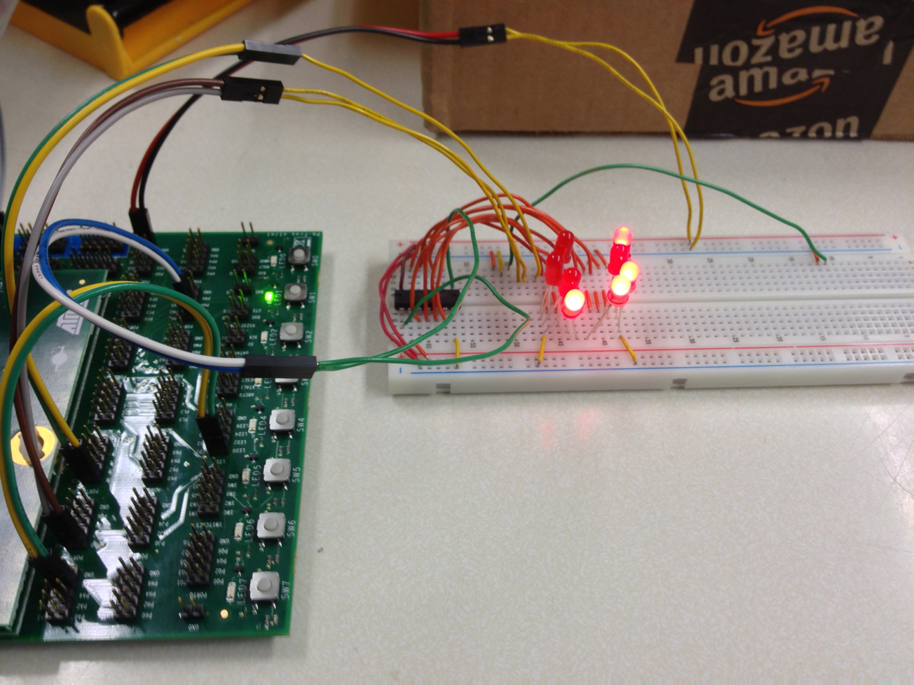
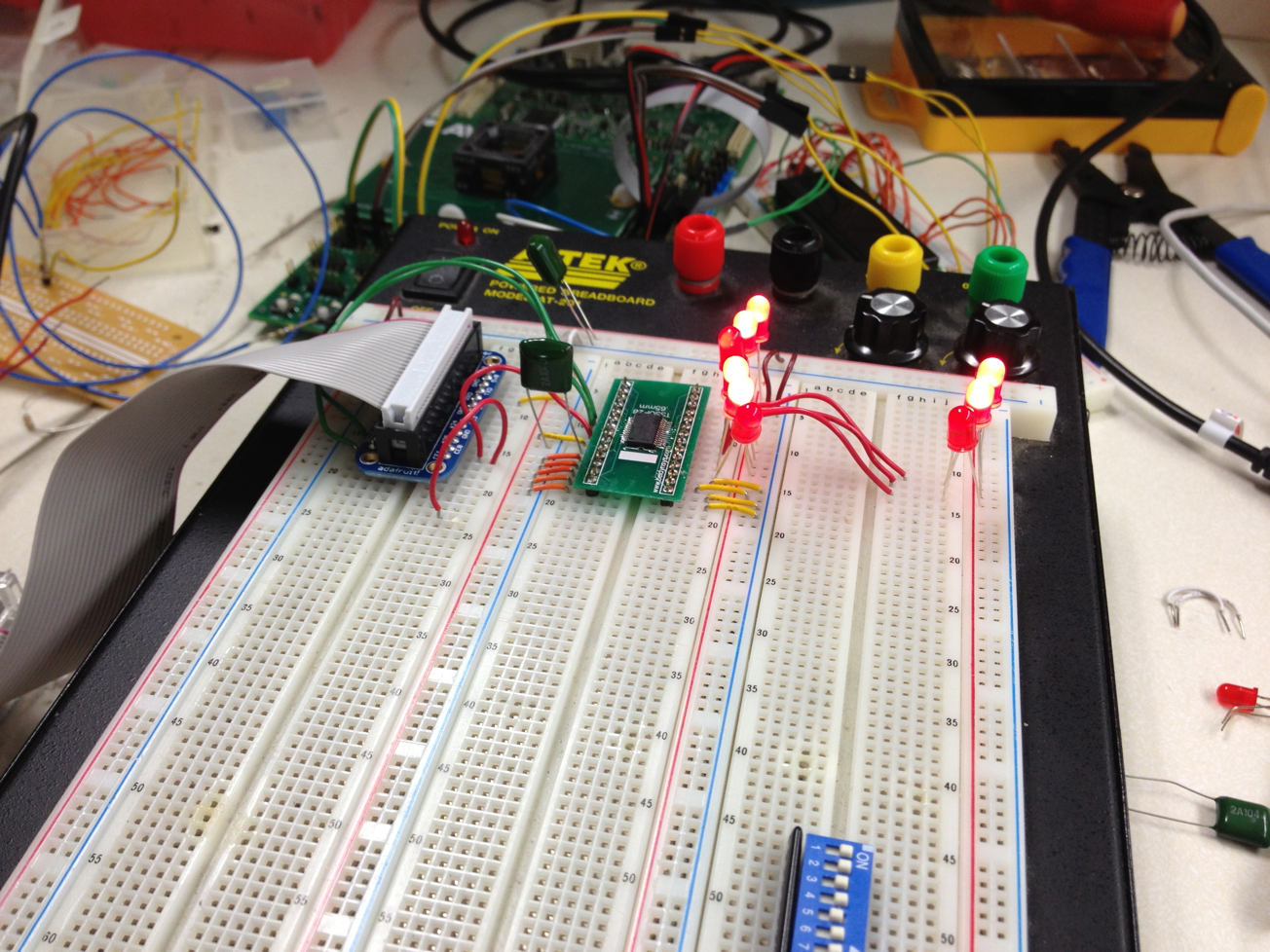
- Successfully tested Omron LED drivers using Raspberry Pi.
- During previous attempts to test these drivers, I had connected the SPI pins of the Raspberry Pi to a 74*164 shift register with individual LEDs connected to each output pin. I had then attempted to send data from the Raspberry Pi to the shift register via SPI just as a simple test, but to no avail. This time, when attempting to perform the same test, I discovered that I had inadvertently connected the shift register to the I2C pins instead of the SPI ones. Fixing this solved the problem. A photo of the test circuit mentioned is shown below:

- I tested the LED drivers with the code I had previously developed for them that made use of the spidev Python module. The code worked well and I plan to add additional functionality to make managing sets of LEDs easier. A photo of the LED drivers being run by the code mentioned is shown below:
WEEK 12 SUMMARY
- Accomplishments: Researched options for replacing Kinect/Raspberry Pi combination as motion detection subsystem. Successfully tested LCD backlight using GPIO, microcontroller UART, and Omron LED drivers using the Raspberry Pi's SPI.
- Weekly Work Total: 14 hours
- Project Work Total: 184 hours
Week 13
April 2, 2013 (6 hours)
- Successfully passed logic signals through logic-level translator. Previously, the voltage levels of the lower logic level output signals were being pulled up from the intended 3.3 V level to approximately 4.2 V by some unidentifiable source. This was resolved by connecting the translator's tri-state enable input pin to a 3.3 V logic high, rather than the 5 V power rail.
- Successfully used the logic-level translator in conjunction with the microcontroller and Raspberry Pi to perform cross-device UART communication. A photo of this occuring is shown below:

- Attempted to program microcontroller soldered on PCB, but with no success. We have apparently not yet determined the proper equipment setup for programming the microcontroller. The pins on the boards are poorly marked and the Atmel Studio software cannot identify that it is even connected to a microcontroller at all. Mark attempted to remove some excess solder from some of the device's pins, but this doesn't seem to have had any effect.
April 3, 2013 (6 hours)
- Further attempted to program microcontroller on PCB, but with no success.
- Consulted lab manager Joe for ideas on how to debug this issue. After checking all of the usual trouble spots, he suggested checking the JTAG signals with the oscilloscope. He then soldered some 2x5 headers together to allow us to effectively attach scope probes to each of the wires of the ribbon cable connecting the programmer and microcontroller's JTAG pins.
- The STK600 development board malfunctioned several times during our debugging of the PCB microcontroller, causing significant delay. The board seems to react very negatively to transient currents induced by attaching and removing jumper wires while it is powered. Doing this causes the status LED to blink red at a moderate rate and can only be fixed after several power cyclings and attempts to reprogram the microcontroller mounted on the board. I have yet to find a method of supplying adequate power to components being prototyped with the board without tripping this built-in surge protector.
- Assisted Jackie with initially testing WiiMote compatibility with the Raspberry Pi using a Bluetooth dongle. Testing was highly successful and indicated that WiiMote buttons and accelerometers can both be easily used.
- Worked on further development of microcontroller software.
- Set up new Atmel Studio project for production game code and began coding game setup routines for the microcontroller.
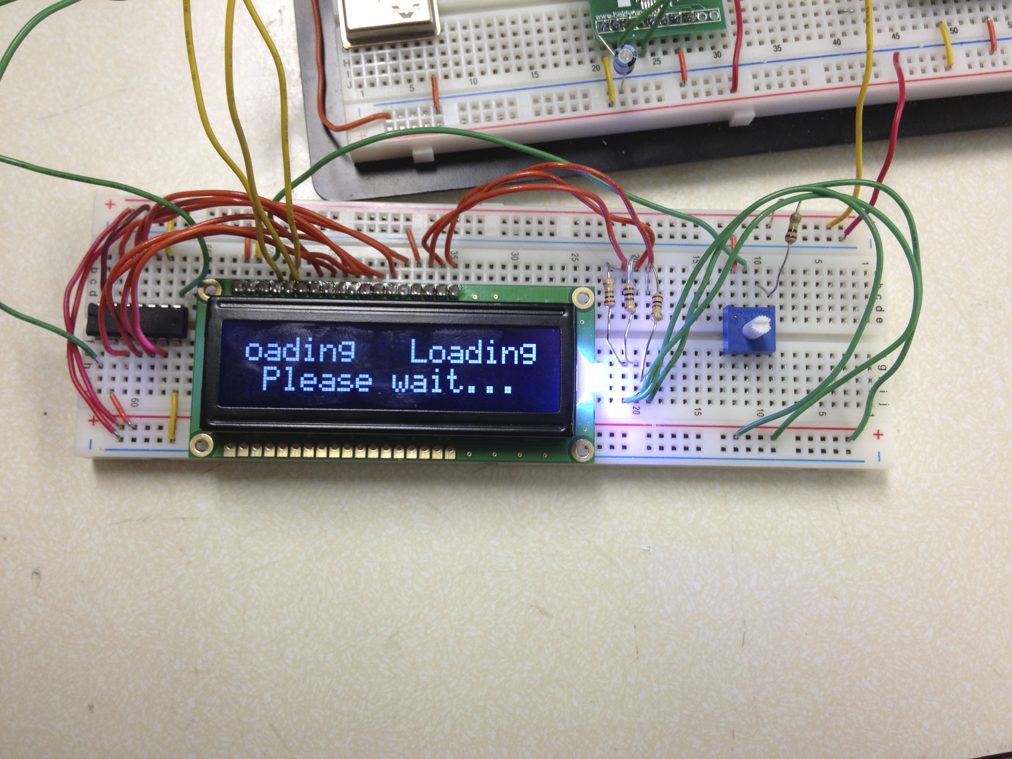
- Experimented with software needed to scroll LCD text from right to left. A photo of this in operation is shown below:
April 4, 2013 (4 hours)
- Successfully programmed PCB microcontroller.
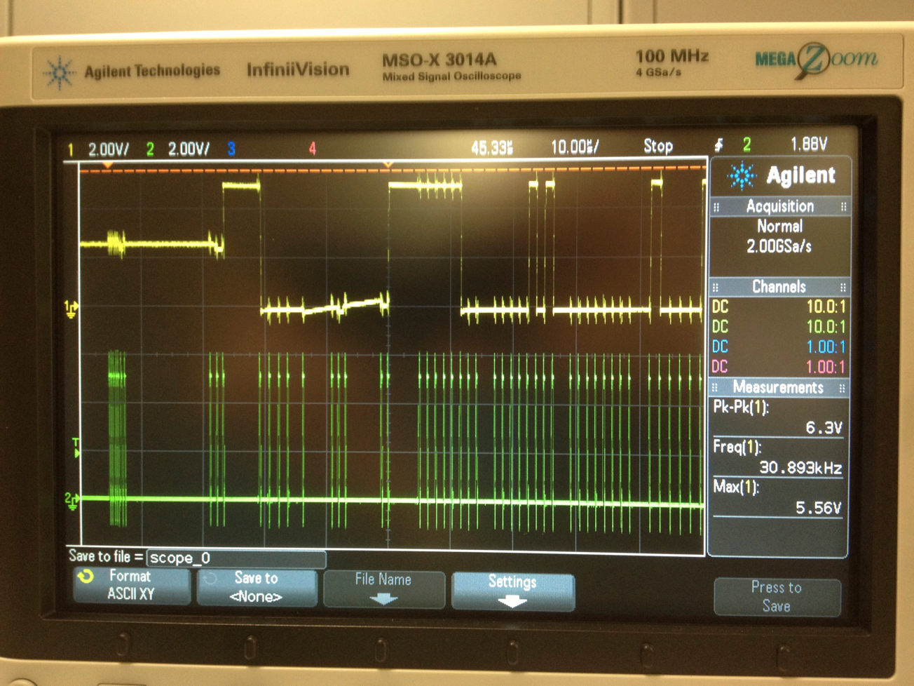
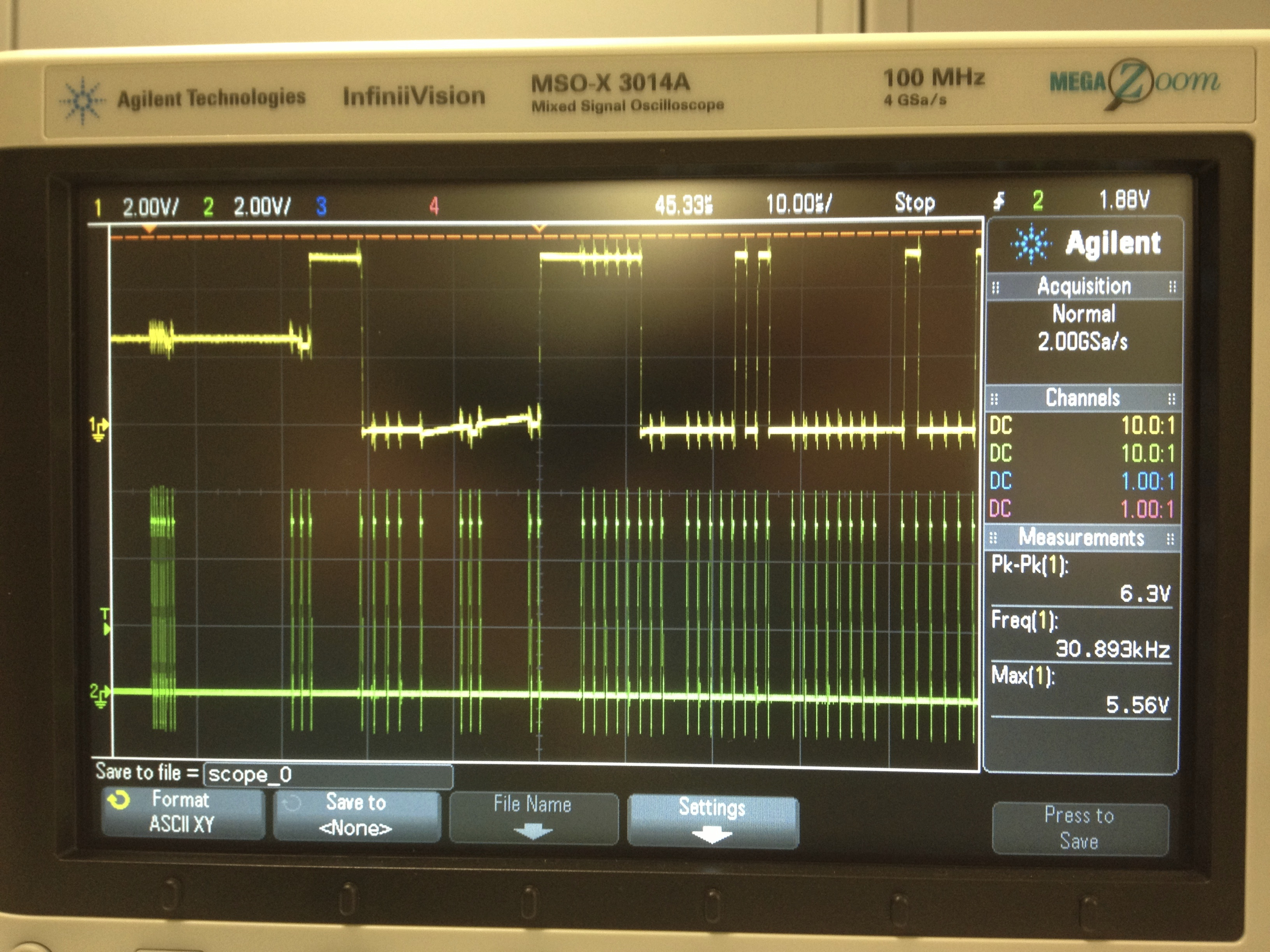
- Debugged JTAG signals with Joe using oscilloscope. During this process, I noticed that the TCK and TDI pins appeared to have the exact same signal as measured by the oscilloscope. A quick inspection of the PCB revealed that these two pins were soldered together, and removing the soldered bridge allowed the microcontroller to be programmed successfully.
- Photo of oscilloscope screen during debugging shown below:
- Removed capacitors from PCB microcontroller power pins and replaced with surface-mount multi-layer ceramic capacitors of similar value. The 2.2 uF capacitors needed for bulk capacitance were replaced with 10 uF ones while the 0.47 uF capacitors needed for decoupling were replaced with 0.1 uF ones.
WEEK 13 SUMMARY
- Accomplishments: Tested WiiMotes with Raspberry Pi. Resolved issue with logic-level converter and sent data between microcontroller and Raspberry Pi. Programmed microcontroller on PCB for the first time.
- Weekly Work Total: 16 hours
- Project Work Total: 200 hours
Week 14
April 8, 2013 (4 hours)
- Wrote and debugged microcontroller code for circular receiving buffer for UART commands. Researched how to enable interrupts on UART receive Atmel Software Framework documentation and configure interrupt handler functions, then created circular buffers structure and wrote handler function to put received characters in the buffer. This was necessary because the microcontroller's UART would malfunction if a second character was received before the first was read. Using this new buffer, incoming commands from the Raspberry Pi can be queue up before they can be processed by the polling loop.
April 10, 2013 (6 hours)
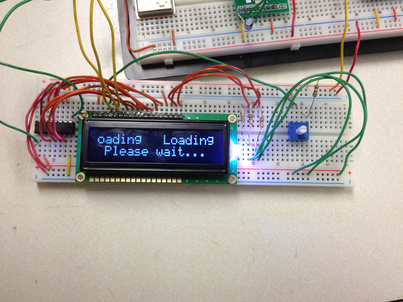
- Debugged microcontroller LCD messages, including messages for welcome, waiting for Raspberry Pi to boot, and connecting controller. Most of the functions associated with these messages had to be rewritten due to subtle changes in the overall code structure.
- Tested PCB shift register on PCB, but with no response. We suspect that, although the microcontroller can now be programmed, the pad drivers for many of the pins may be destroyed. We plan to replace the microcontroller on the PCB with a spare and see if that changes anything.
April 11, 2013 (6 hours)
- Integrated Jackie's work with WiiMotes into the software on the Raspberry Pi. The two of us took time to discuss the work I had done on the overall code structure thus far before I handed it off to her. We added support for both connecting to the WiiMotes and acknowledging button presses.
- Updated various game setup menus on the microcontroller. Jackie and I decided to add a "select number of players" menu which doubles as the selector for the practice/duel mode. It also helps the Raspberry Pi determine whether or not connecting a second controller is necessary. Also, the song selection menu was adjusted to be easily expandable to as many songs as we wish to put on the device.
- Replaced microcontroller on PCB and tested many subsystems successfully.
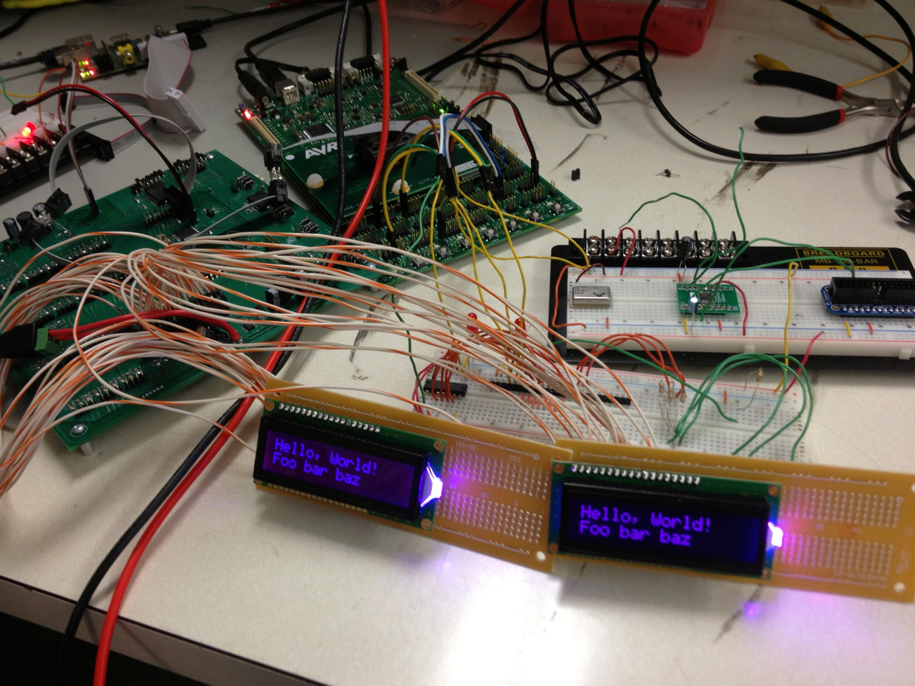
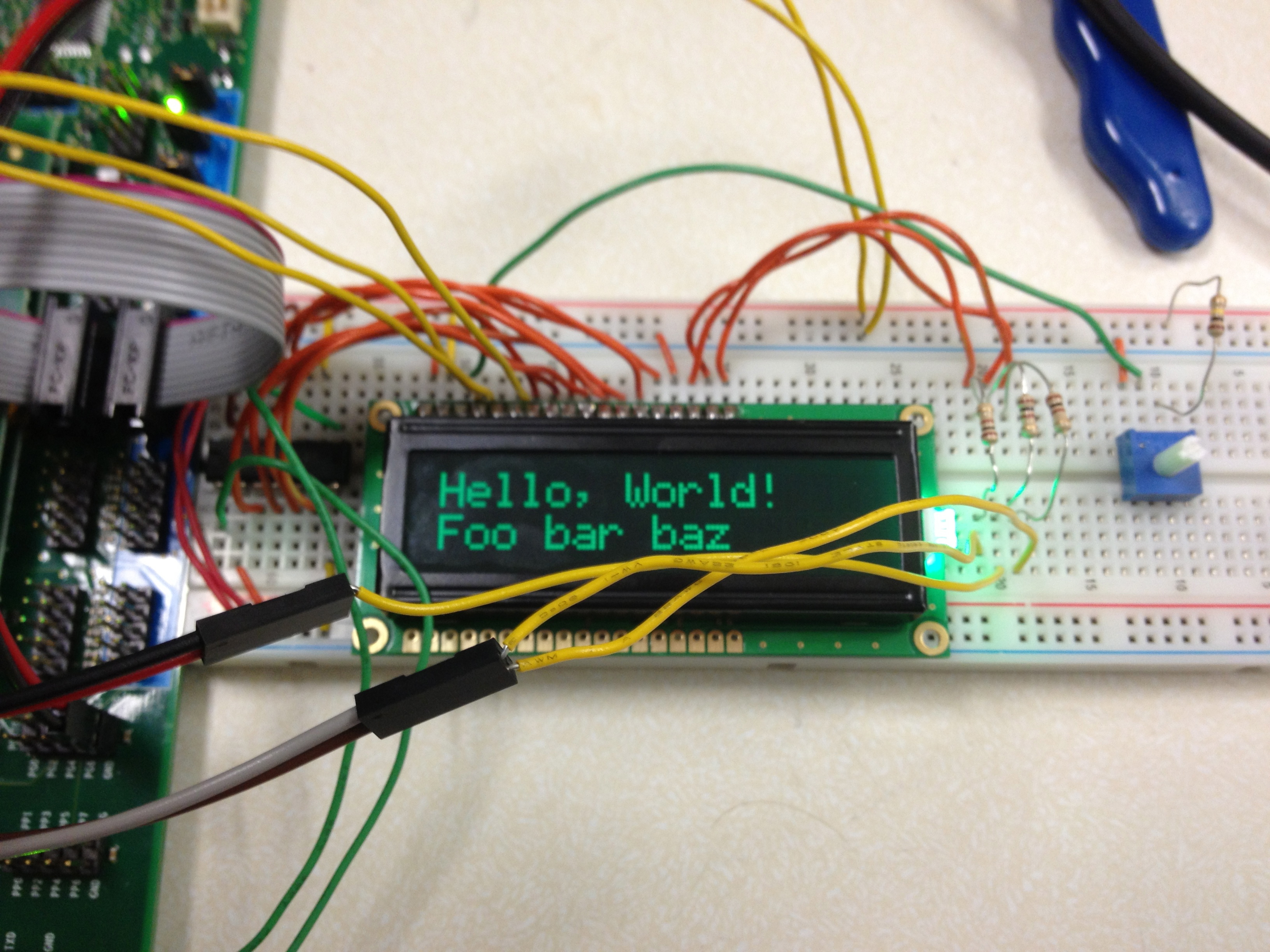
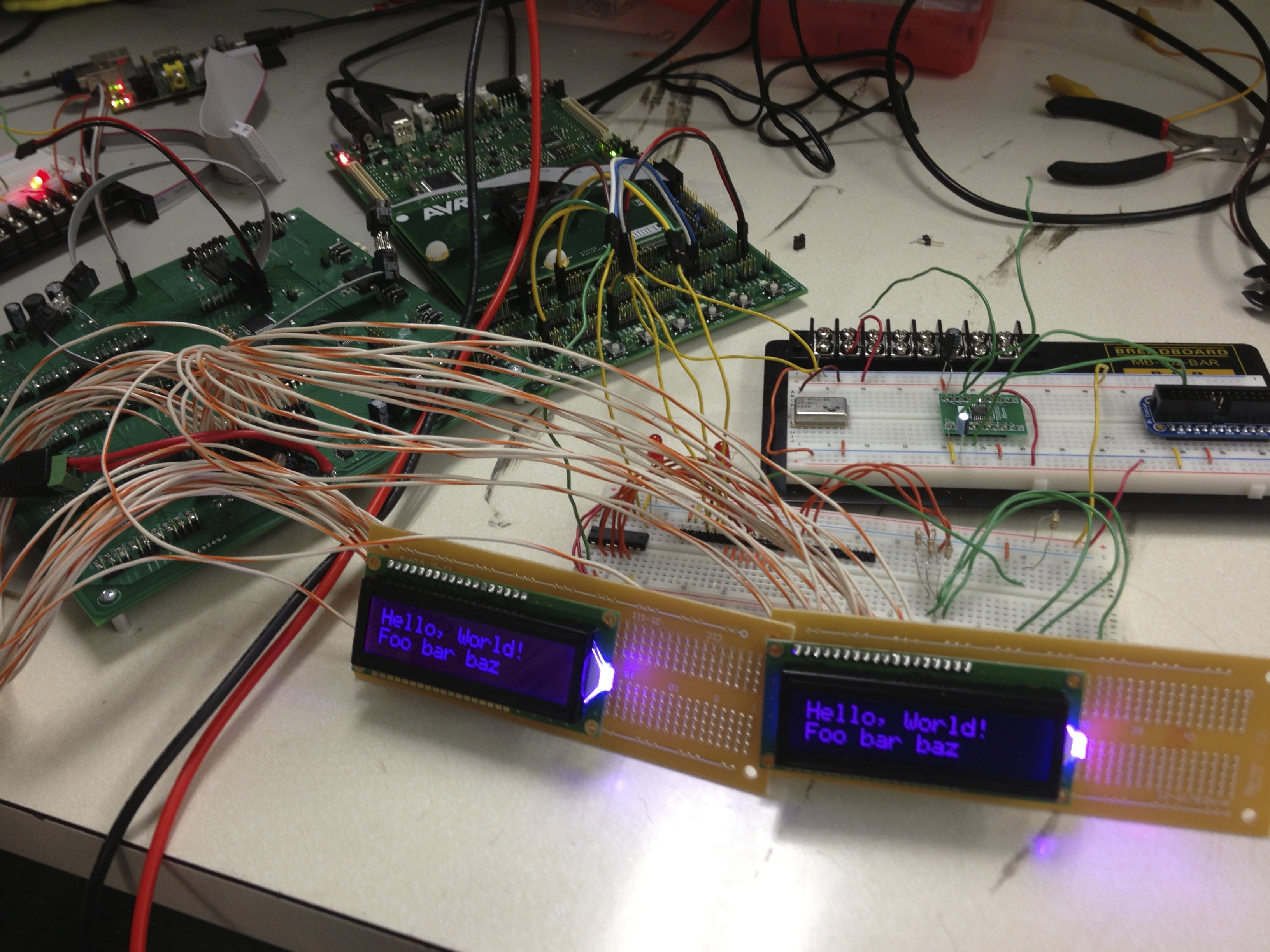
- Tested microcontroller with shift register and LCD assemblies which Duncan finished. Both LCDs are fully operational, as shown in the image below:
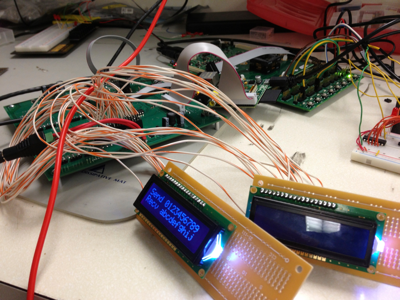
- Tested microcontroller with Raspberry Pi via logic level translator on PCB. This system is also fully operational, as shown in the image below:
April 13, 2013 (6 hours)
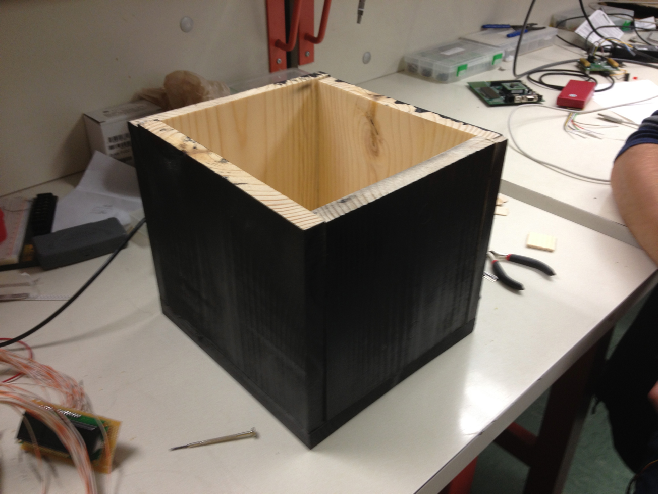
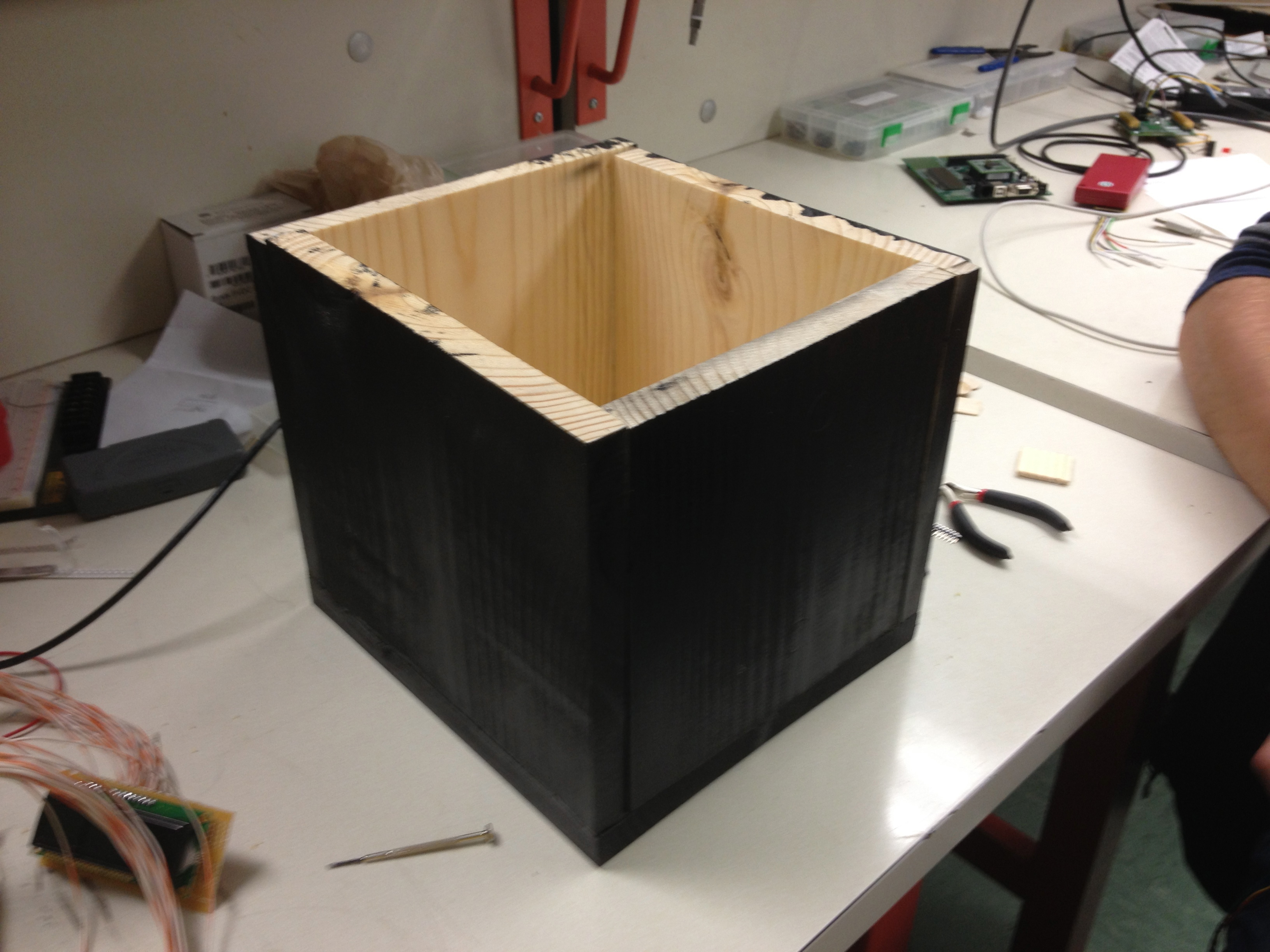
- Assisted Mark with construction of packaging.
- The switch to using WiiMotes means that the players no longer need to stand next to each other on the same side of the device to use it, and thus the LCDs no longer need to be mounted on one side facing the players. As a result of this, we simplified the packaging design to be just a box with the robot arena as the top with the LCDs mounted on opposing sides. This way, the players can stand and face off against each other as well as stand behind their robots, just like in the original game.
- Glued together three of the four sides of the box to the base board. Also helped Mark with removing extraneous plastic pieces from the arena underside and expanding the size of the holes on the top to fit the modified robots.
- Further tested H-bridges with Mark and determined that they are destroying microcontroller pins. We are not certain as to how this is happening, but we think that either some form of kickback or excess current is being pulled from the microcontroller by the H-bridges, destroying the pad drivers. We have decided to try to add optical isolation these pins to see if that fixes the problem.
WEEK 14 SUMMARY
- Accomplishments: Completed majority of microcontroller game and menu code. Tested PCB microcontroller LCD and UART interfaces. Began construction of packaging.
- Weekly Work Total: 22 hours
- Project Work Total: 222 hours
Week 15
April 15, 2013 (6 hours)
- Fixed H-bridge problem of destroying microcontroller pins with Joe's help. Joe suggested putting current limiting resistors in series with each pin, which worked perfectly and was far easier to do than flywiring optical isolators into the device.
- Tested actuators with H-bridges and fixed a design flaw. We had originally connected a 10 watt, 10 ohm sensing resistor to the H-bridges being used for the actuators in the hopes that it would act as a current limiting resistor for each actuator pin. In practice, this did not work due to a voltage limitation of the sensing resistor connection pin on the H-bridge, so we put a resistor in series with each pair of actuator pins/H-bridge output pins to limit the current instead.
April 17, 2013 (4 hours)
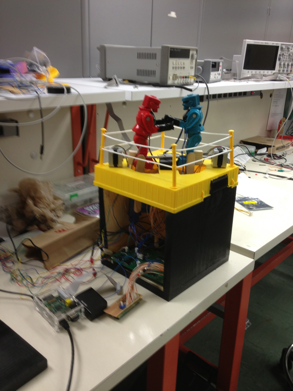
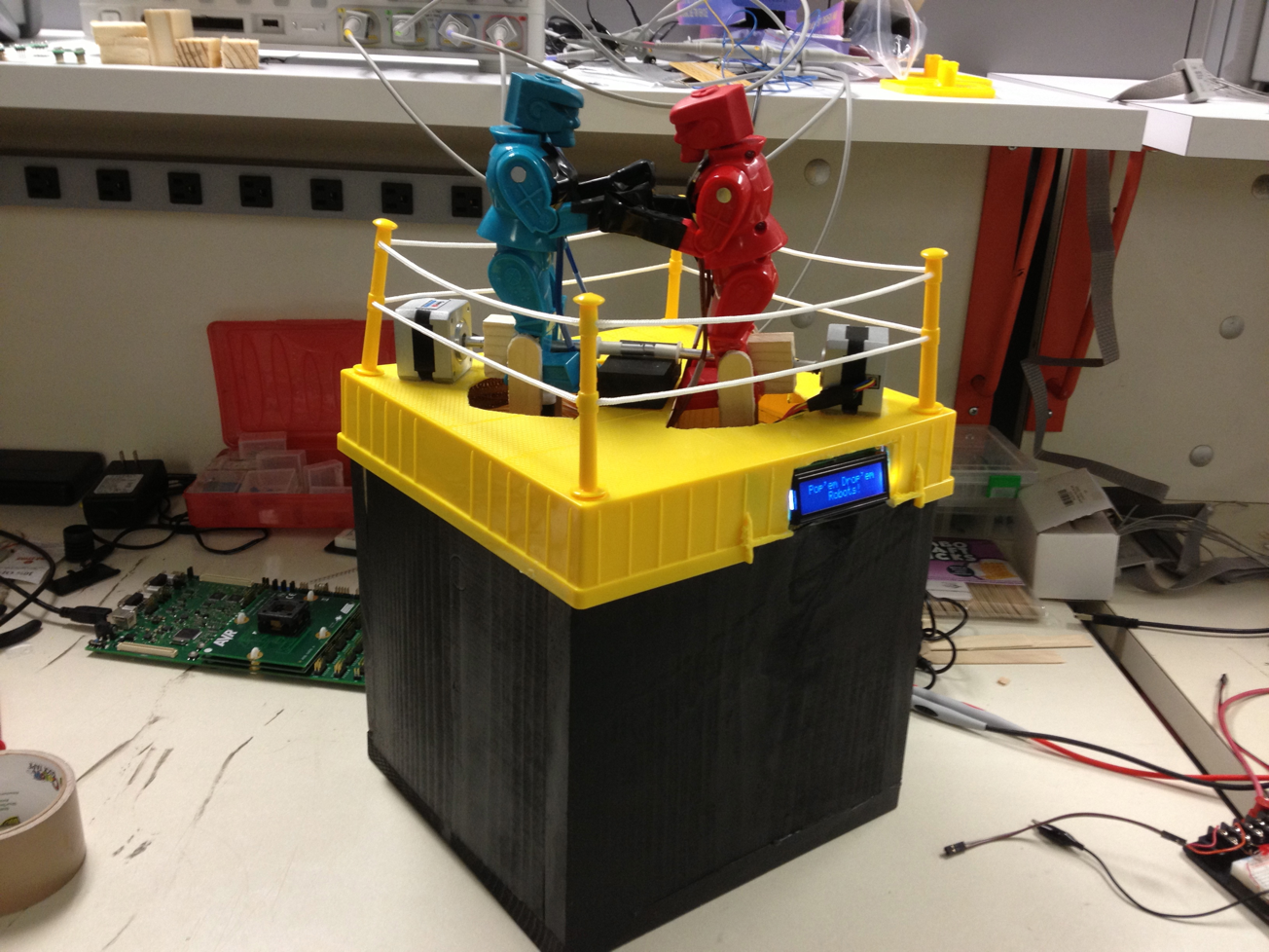
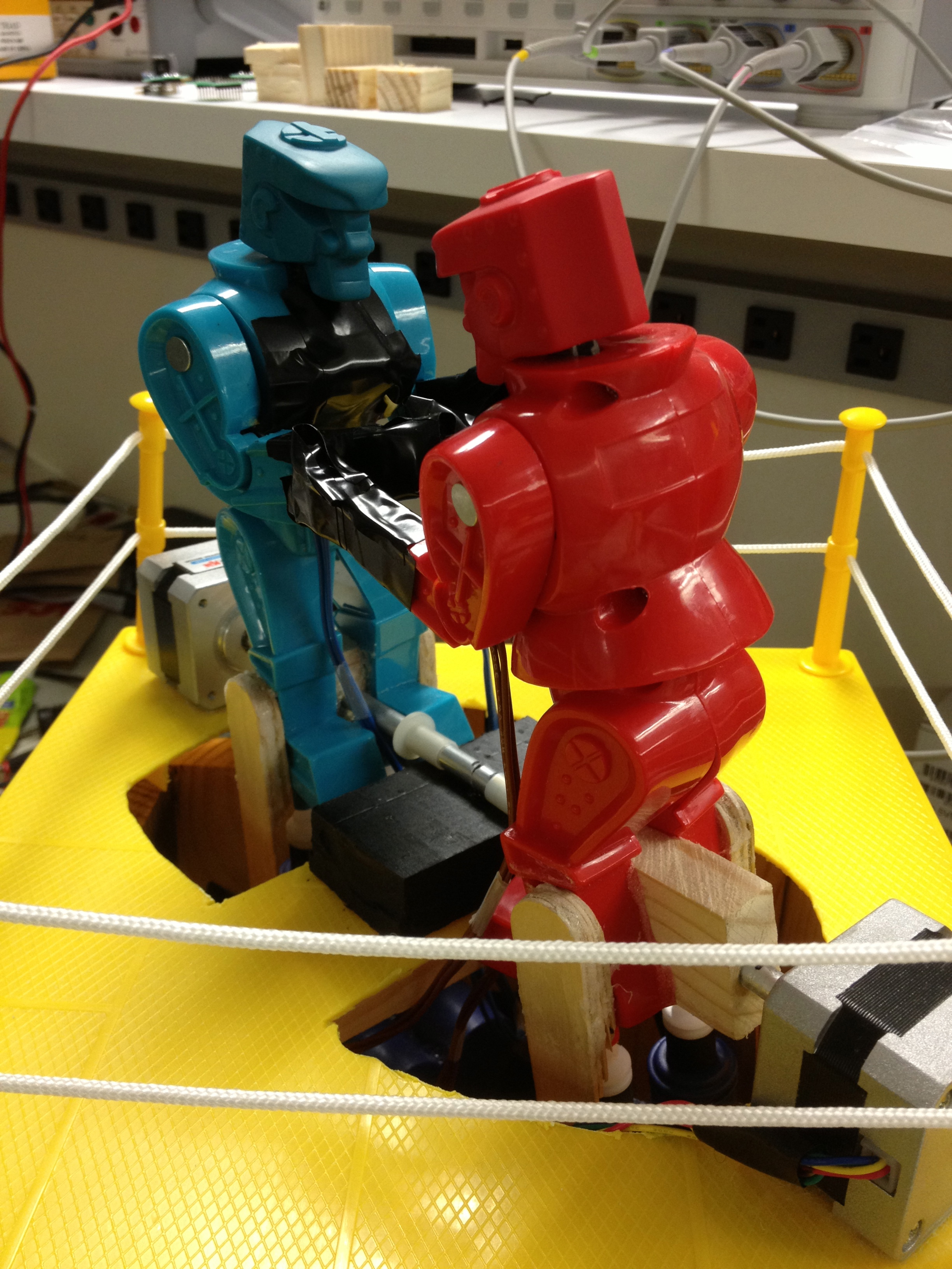
- Completed assembly and painting of packaging with Mark's help. Images of completed packaging and nearly-finished device are shown below:
- Wrote code for driving actuators and stepper motors. The code for the stepper motors appears to need more work as they sometimes do not rotate in the intended direction. They also do not appear to be as powerful as we had originally hoped with the entire robot and actuator assembly mounted on them.
- Successfully operated device navigating all menus and with successful punching and hit detection for first time. Duncan attached magnets to the chests of each robot, and after testing out the Hall-effects and fixing several solder connections, we were able to have two users punch each other at the same time using the WiiMotes. Most of the punches were detected by the Hall-effect sensors and the player's health updated accordingly, but the placement of the magnets will need to be adjusted.
WEEK 15 SUMMARY
- Accomplishments: Resolved issues with H-bridges. Completed motor driver code. Successfully tested actuator and stepper motor control and driving. Successfully tested full device operation with game menus, connecting WiiMotes, playing audio, allowing players to punch each other, detecting hits, and updating player health accordingly.
- Weekly Work Total: 10 hours
- Project Work Total: 232 hours
Week 16
April 22, 2013 (6 hours)
- Modified microcontroller code to forfeit a player if they press the A button on their WiiMote. This allows for a quick exit from main gameplay and easier testing of the overall device operation.
- Finished assembly of project and packaging. All components have been connected, attached, and the game is fully packaged for use. Images of the finished product is shown below:

- Researched and implemented script to run Raspberry Pi software on startup. This allowed the device to be run fully in a "turn-key" style of operation where, on power-up, the microcontroller boots and waits for a signal from the Pi indicating that it has booted as well. Normal operation of the game proceeds until the player declines to play again, at which point the microcontroller waits 30 seconds for the Pi to shutdown, then indicates to the user that it is safe to remove power from the device.
- Worked with Duncan and Mark to create PSSC demo video. A YouTube link to the video can be found here.
April 23, 2013 (1 hour)
- Fixed issue with LCD RGB LED backlight control code. Previously, whenever I tried to change the color of the backlight, the result was always the wrong color. By cycling through the various color options on both LCDs, I determined that the pin mappings for the blue LED control pins of the two LCDs were swapped. Fixing this allowed the correct colors to be displayed, so I added backlight color changes into the game code for various menus just to enhance general effect.
WEEK 16 SUMMARY
- Accomplishments: Completed entire project, received PSSC credit, and demonstrated at Royal Design Showcase
- Weekly Work Total: 7 hours
- Project Work Total: 239 hours


