Project Description
 |
Conventional cameras networks require an infrastructure of cables and computers to transmit, store and process the information coming from the cameras. In many applications, it is undesirable, or even impossible to have such infrastructure. As a consequence, there has been increasingly more focus on the substitution of conventional cameras by wireless smart cameras, i.e., wireless cameras endowed with processing power, capable of making local decisions before transmitting data over the network. However, to make wireless smart cameras viable, it is necessary to extend the lifetime of the batteries as long as possible. Therefore, the hardware architecture of such devices is highly constrained. As a consequence, performing even very simple processing tasks efficiently is extremely challenging. |
In our wireless cameras project, we use a network of Cyclops cameras attached to MicaZ motes to track an object based on its color information. Figure 1 show the Cyclops camera and the MicaZ mote.

Figure 1: Cyclops camera attached to a MicaZ mote
It is well known that local data aggregation is an effective way to save sensor node energy and prolong the lifespan of wireless sensor networks However, when sensor networks are used for event-driven applications such as object detection and tracking (as opposed to environment monitoring applications), not all sensors provide useful information at the same time. Therefore, the goal in event-driven clustering is to dynamically select a subset of sensors that can provide information about the target based on the physical position of the event source and on the characteristics of the sensors. Most of the existing event-driven clustering algorithms assume that the distances between the sensors and the event-generating targets are somehow related to the ability of the sensors to detect the target. In wireless camera networks however, the distance-based criteria for sensor node clustering are not sufficient because, depending on their viewing directions, physically proximal cameras may view segments of space that are disjointed and even far from each other. That means that, even when a single object is being tracked, a clustering algorithm must allow for the formation of multiple disjointed clusters of cameras for tracking the same object. An example is illustrated in Figure 2 where, in spite of the fact that the cameras in cluster A cannot communicate with the cameras in cluster B, both clusters can track the object. Therefore, multiple clusters must be allowed to track the same target.
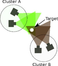
Figure 2: Multiple clusters tracking the same object in a wireless camera network, dotted circles represent the communication ranges of the clusters
Dynamic cluster formation requires all cluster members to interact to select a cluster head. After clusters are created to track specific targets, they must be allowed to propagate through the network as the targets move. That is, clusters must be able to accept new members into the cluster as they identify the same object, remove members that can no longer see it, and assign new cluster heads as the current head leaves the cluster. Since multiple clusters are allowed to track the same target, when a cluster head leaves the cluster, mechanisms must be provided to account for the possibility that the cluster be fragmented into two or more clusters. In addition, if these clusters overlap they must also be able to coalesce into a single cluster. Even when cluster merging is not required, it is necessary to provide mechanisms to allow inter-cluster interactions since neighboring clusters may need to share information. Therefore, our clustering protocol addresses the following issues:
- Head election
- Propagation
- Coalescence
- Fragmentation
- Inter-cluster interactions
After a cluster is created, cameras within this cluster are able to share information about the target with very small overhead, and the information shared by the cameras is automatically carried by the cluster as it propagates. This clustering protocol provides a natural framework for data aggregation using a decentralized Kalman filter wherein data acquired by the cameras is processed by the cluster head and the estimated target position is carried along with the cluster as it propagates. Using this approach we constructed a color-based object tracking system.
In order to illustrate the performance of the system in practice, we implemented the object tracking system in a real network of wireless cameras consisting of 12 wireless cameras mounted on the ceiling of our laboratory. The cameras are spaced so that there is partial overlap between the fields of view of the neighboring cameras. The field of view of all the cameras covers a region of about 5 by 3.5 meters (16.4 by 11.5 feet). Figure 3 shows a picture of our wireless camera network. The cameras were calibrated by the calculation of planar homographies between the floor of the laboratory and the camera planes. Thus, as the object to be tracked moves on the floor, each camera that sees the target is able to compute the coordinates of the centroid of its image with respect to the world coordinate frame.
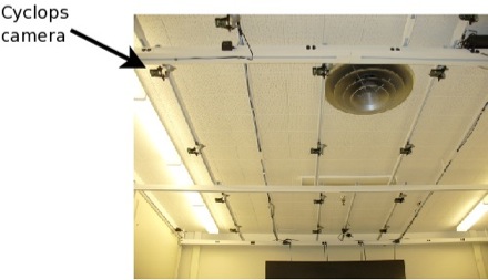
Figure 3: Actual networks of wireless cameras
To visualize the dynamic behavior of the network, we implemented a graphical user interface that displays the clusters during all their phases. Figure 4 shows the display panel of this GUI while the networks tracks two targets of different colors (red and blue). The blue circle represents a cluster head and green circles connected to the cluster head by solid lines represent cluster members. Gray circles represent cameras that do not belong to any cluster. Yellow solid lines represent the connections among cluster members and their respective cluster head. The yellow dashed line represents a connection that should have been established but was not due to a communication failure. The red (blue) ellipses represent the 95% uncertainty region of the red (blue) target position with respect to each camera that can detect the target. The cluster head aggregates these measurements in order to estimate the target position. The expected value of the target position is displayed at the left bottom of the screen. The numbers inside the ellipses correspond to the object identifiers. The large rectangles correspond to pieces of furniture present in the room that are represented in the GUI to facilitate in the visualization of the movement of the target.
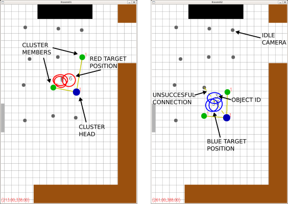
Figure 4: Graphical user interface displaying the hierarchical tracking system
Figure 5 shows the trajectory of the object for three different runs of the experiment. Ground truth data was capture using a wired camera at 30 frames per second and is represented by the solid black lines. The dashed lines show the trajectory of the target as computed by the wireless cameras. The markers placed on the dashed tracks correspond to the actual target positions computed by the wireless cameras. The reason for showing both the trajectory with the dashed line and the markers on this line is to give the reader a sense of when the system loses track of the target. Each time the track is lost, the system creates a new object identifier for the moving target and the target state is reinitialized based on the most recent measurement.

Figure 5: Tracking performance for three different runs of the tracking experiment
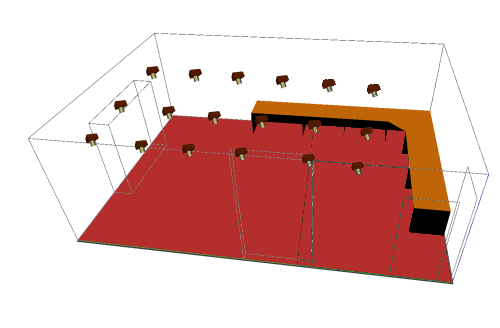
To evaluate the performance of our algorithm, we also carried out a number of experiments in a simulated multi-hop network. We implemented a camera network simulator that provides the pixel coordinates of a moving target based on each camera's calibration matrix. Figure 6 show the graphical user interface of the simulator. The red lines connecting pairs of cameras indicate communication links between camera nodes, and the green tetrahedral volumes represent the fields of view of cameras.
The simulator creates a target that moves randomly or that follows a predefined trajectory in the xy plane in the world frame. The simulated cameras operate independently and the data generated by each camera is output via TCP connection to an individual node in a sensor network simulation using Avrora. Our Kalman filter code, along with the clustering protocol, are executed directly in Avrora.
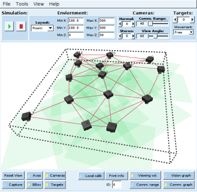
Figure 6: Wireless Camera Network Simulator
To evaluate the accuracy of our algorithm, we introduced Gaussian random noise into the camera measurements and compared the root mean squared error of the estimates obtained to the error of a centralized tracking method in which all the data collected by the network was processed by a centralized Kalman filter. Figure 7 shows plots of the error of the unfiltered data, of our distributed Kalman filter, and that of the centralized Kalman filter as a function of the standard deviation of the measurement noise. Our algorithm is able to substantially reduce the error in the unfiltered data. Although the centralized Kalman filter is able to provide more accurate results, it requires the transmission of all the data to the base station.
To illustrate the potential energy savings obtained by restricting the number of multi-hop messages transmitted by the system, we measured the average number of messages transmitted per node per minute using our Kalman filter algorithm and the average number of messages needed to transmit all the information to the base station. Figure 8 shows that, when the average distance to the base station is small, the number of messages transmitted by our algorithm is higher than transmitting all the data to the base station due to the overhead introduced by clustering. However, as the average distance to the base station grows, eventually a threshold is reached where sending all the messages becomes more expensive than creating the clusters. This threshold depends on the sampling period of the cluster-based Kalman filter. For example, for the case of a sampling period of 750ms, the cluster-based approach performs better than the centralized approach for an average distance to the base station larger than 2 hops.
 Figure 7: Root mean squared error of the target position as a function of the standard deviation of the pixel noise |
 Figure 8: Number of messages transmitted by the system as a function of the average distance to the base station |
Project Team
| Henry Medeiros | Johnny Park |
Publications
-
Distributed Object Tracking Using a Cluster-Based Kalman Filter in Wireless Camera Networks
H. Medeiros, J. Park, and A. C. Kak, "Distributed Object Tracking Using a Cluster-Based Kalman Filter in Wireless Camera Networks," in IEEE Journal of Selected Topics in Signal Processing, vol. 2, no. 4, pp. 448-463, August 2008. -
A Light-weight Event-driven Protocol for Sensor Clustering in Wireless Camera Networks
H. Medeiros, J. Park, and A. C. Kak, "A Light-weight Event-driven Protocol for Sensor Clustering in Wireless Camera Networks," First ACM/IEEE International Conference on Distributed Smart Cameras, September 25-28, 2007.