Sensor Selection Problem in Large Camera-Based Sensor Networks
Modern navigation, mapping and surveillance systems require numerous vision sensors to be mounted at random locations over a geographically large area. One of the most important research issues in this field is the problem of selecting a small subset of sensors in the network that will carry out the requested task most efficiently. In this project, we have developed an algorithm to create distributed look-up tables that will rank cameras according to how well they can view a specific location, thus facilitating selection of best cameras.

The look-up table at every camera node covers all the points within the corresponding cameras viewing frustum by optimally dividing the volume. The process of updating the lookup table is incremental, thus can easily be used in a dynamic network. In real time applications, we can achieve:
1. Significant reduction in processing time as the computationally expensive task of finding the best cameras is replaced by a simple look-up operation, and
2. Considerable reduction in network traffic that would otherwise be needed to carry out the process of camera selection.
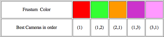
The images show the look-up table generation process. The viewing frustum of each camera is divided into 5×5×5 smaller frustums. For visualization purpose, we are showing only a single layer of sub-frustums of only one camera, C1. The frustums are color coded to show the sorted order of cameras best suited to image that sub-frustum, as given by the following legend:
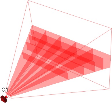
The Figure shows a camera and a single layer of its viewing frustum.

Camera C2 is added to the system and it broadcasts its frustum coordinates to camera C1.
Now the look-up tables are updated to give the new ranking of best cameras for each sub-frustum
Now the look-up tables are updated to give the new ranking of best cameras for each sub-frustum

Camera C3 is added and the look-up table of camera 1 is updated again.
The following simulation shows a network of 20 cameras, each with the distinct color. Color coded look-up tables for three separate cameras are shown. The color of each sub-frustum represents the color of the most favorable camera. All look-up tables consist of 10×10×10 sub-frustums.


• Josiah Yoder
• Johnny Park

J. Park, P. C. Bhat, and A. C. Kak, "A Look-up Table Based Approach for Solving the Camera Selection Problem in Large Camera Networks," Workshop on Distributed Smart Cameras, in conjunction with ACM SenSys'06, 2006 [pdf]