Stereo Vision for Bin Picking of Complex 3D Objects
One of the biggest challenges in computer vision is to use regular 2-D vision for recognition and pose estimation of complex industrial parts. In our laboratory, we now have developed a system that uses two off-the-shelf cameras for the recognition and pose calculation of objects in scenes as complex as that shown in Fig. 2 below. For such objects in bins, various factors exacerbate the complexity of object recognition and pose calculation, the principal factor being the distortion of object appearance caused by occlusions and exposed background features.


This highly successful project was guided by the following fundamental notions:
• utilize sufficient representation/model of target objects that are invariant to their shape complexity;
• each object model consists of seed features and supporting features;
• Seed features: unique landmark features that are easily identified.
• Supporting features: other landmark features that would support both identification and pose-estimation.
• Supporting features' necessity is due to the limitations of optical devices that generate noisy image formations.
• to reduce the search complexity, achieve focus of attention by segmenting the left and right views and produce regions where
high probability of seed feature existence are present;
• provided with the potential image regions, further analysis confirm or reject the hypothesis of object recognition;
• from the recognition hypothesis, pose-estimate the identified target objects.
In our experiments with the alternator covers shown in Fig. 2 below, their simplified model as shown in Figure 1 was empirically derived. Its large bearing hole is defined as a seed feature, and the four screw holes are defined as supporting features. More specifically, the radius of the bearing hole (r) is 15mm, and the radius from the center of bearing hole to the screw holes (r support) are 22.5mm.
We define pose-estimation as an estimate of the location of the center of the bearing hole/seed feature p, and orientation of the normal vector n. After training the system with this simplified model and objective, the system can then execute the desired bin-picking task. However, instead of attempting to actually grasp the objects, we verify the accuracy of the system by having a gripper-mounted camera normally approach each identified target.
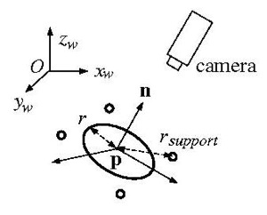
Figure 1 - Simplified model and system objective
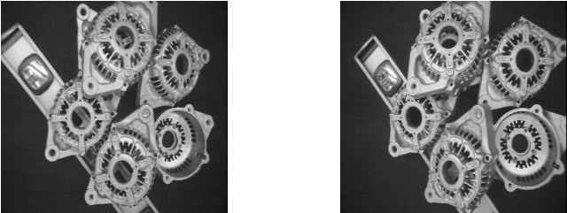
Figure 2 - Initial View. (Left and Right)
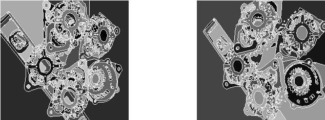
Figure 3 - Segmented Images. (Left and Right)
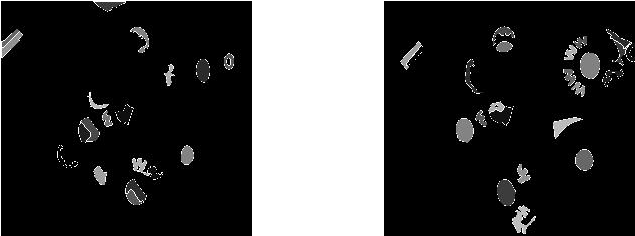
Figure 4 - Automatically extracted regions of interest. (Left and Right)
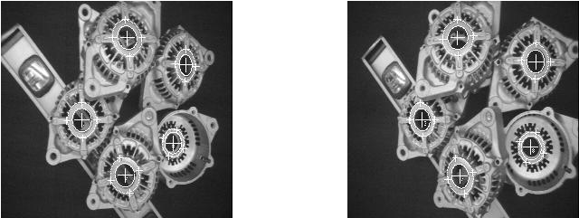
Figure 5 - As a proof of the correctness of the computed pose,
shown here are the model features re-projected into the left camera image. (Left and Right)
shown here are the model features re-projected into the left camera image. (Left and Right)

This MPEG movie shows the robot end-effector approaching each alternator cover after its pose is computed by the stereo vision system. The distance between the center of each large hole and the cross-hairs shows the error in the calculation of some of the parameters of the pose of each alternator cover.

K. Rahardja and A. Kosaka, "Vision-based Bin-Picking: Recognition and Localization of Multiple Complex Objects using Simple Visual Cues,'' IEEE/RSJ International Conference on Intelligent Robots and Systems, Osaka, Japan, November, 1996. [ps, 9.5MB]
A. C. Kak and A. Kosaka, "Multisensor Fusion for Sensory Intelligence in Robotics," Proceedings of the Workshop on the Foundations of Information/Decision Fusion and Applications to Engineering Problems," (INVITED TALK) Sponsored jointly by Department of Energy, Office of Naval Research, and National Science Foundation, August 7-9, 1996, Washington DC. [ps.gz, 0.7MB]