
Pictures
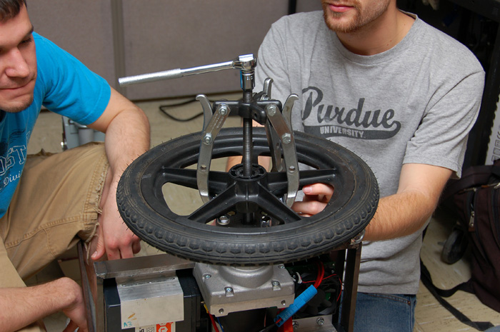
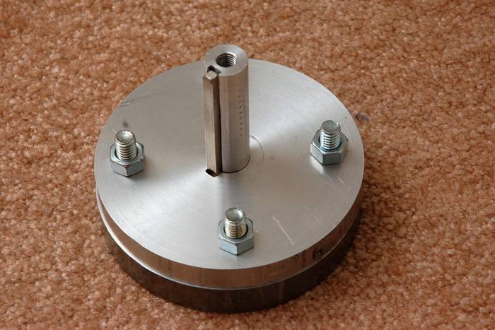
We had some problems with both wheel hubs again. One key was sheared off, and the other hub's bolts backed out. Since the wheels had to be pressed on, they could not be removed by hand. This gear puller (used to remove pulleys from cars) was used to help us remove the wheel so that the hubs could be fixed.
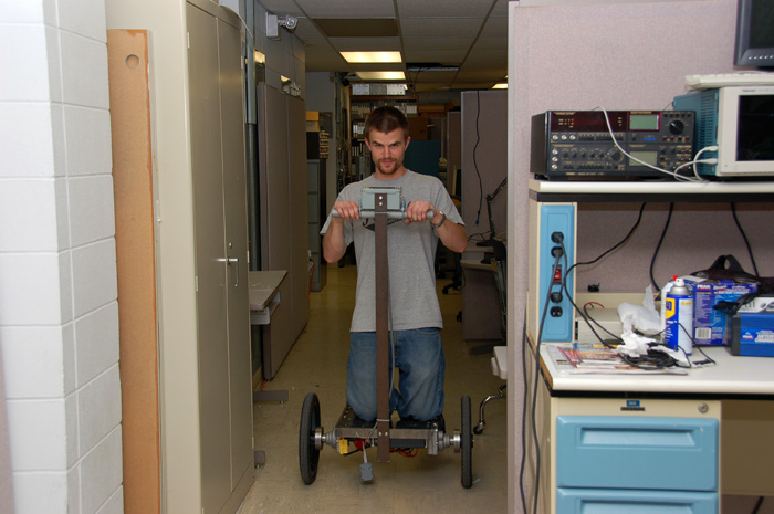
Pete is demonstrating how it would look if a very short person were to ride The Two Wheel Deal. Pretty goofy, in our opinion.
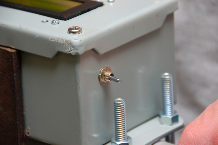
We installed a switch that would allow us to switch the vehicle between standing on its own, or standing flat for a passenger to ride.
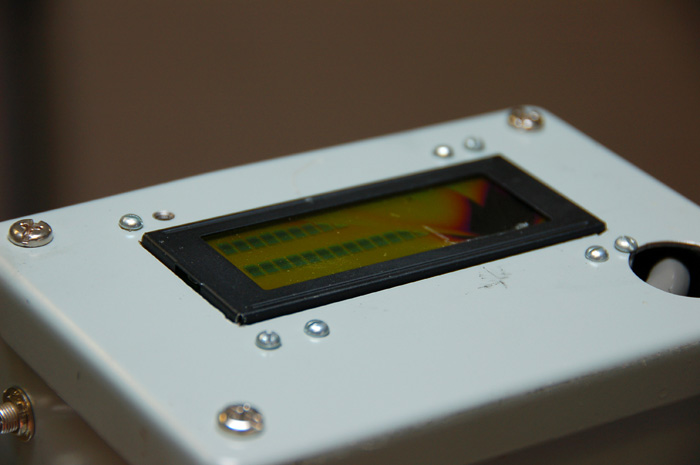
A little accident resulted in the LCD being smashed.
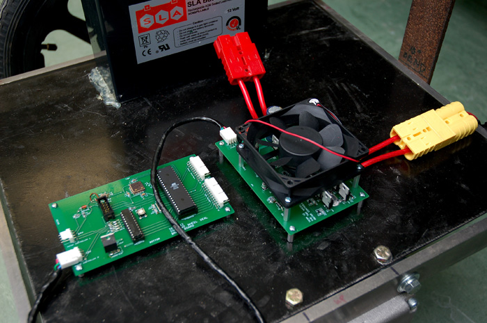
These are the latest shots of The Two Wheel Deal. All of the wires have been tied up and away from the ground, and connectors have been installed to facilitate easy recharging.
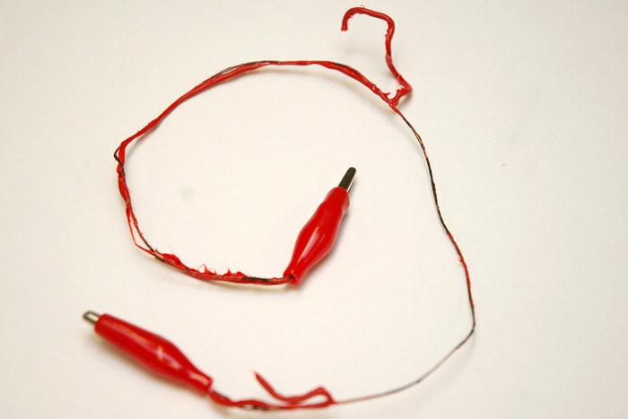
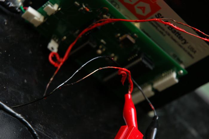
Our means of powering up The Two Wheel Deal is far from refined. Powering up the vehicle always results in a large amount of arcing. The problem is finding a switch that can handle all of the current that is affordable.
These fancy aluminum handlebars were textured with a sandblaster to provide the rider with something to grip onto during those times when The Two Wheel Deal turns into the Two Wheel Rodeo.
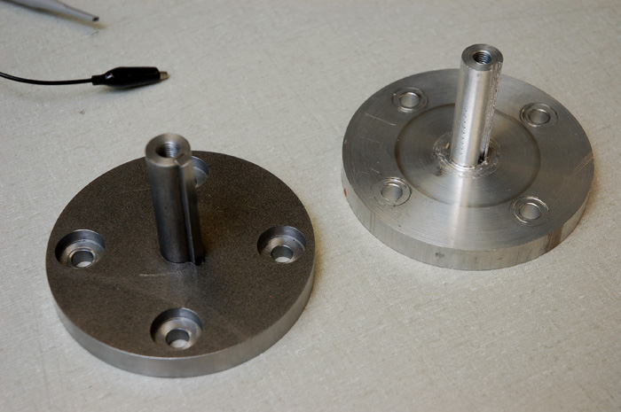
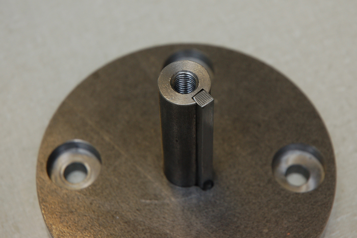
Our first wheel hubs broke. The aluminum was too soft to handle the loads we put on it. These are the new wheel hubs machined out of steel, which are much stronger. A very big thanks to Tom Hinton, who graciously took time out of his weekend to make these.
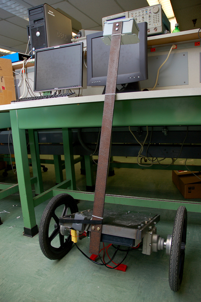
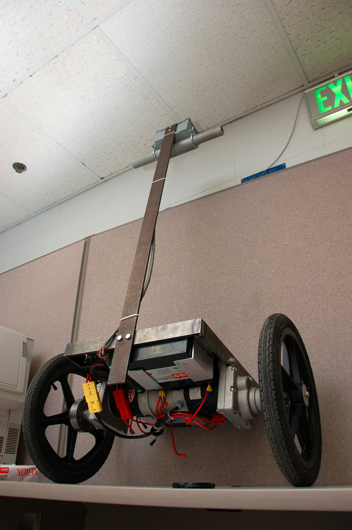
The chassis is almost done! The rusty pole is to give The Two Wheel Deal a more "vintage" look. I am sure that all of us have fond memories of Segways from the 50's.
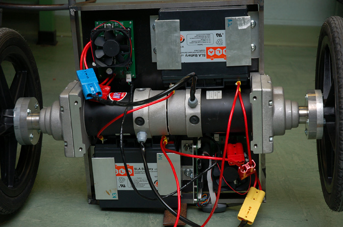
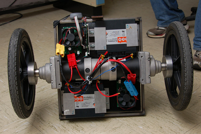
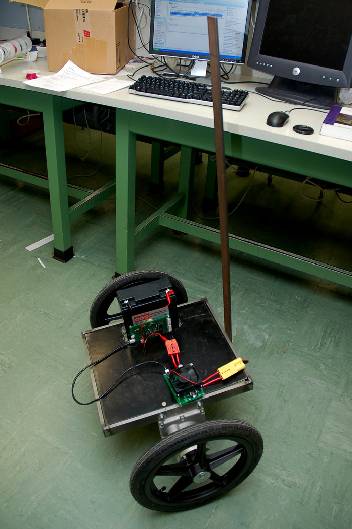
This is the bottom of the vehicle showing the layout of all of the components.
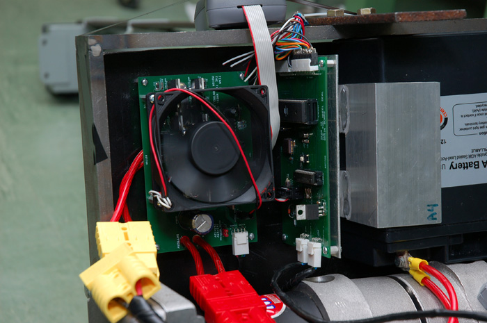
The electronics on the bottom of the vehicle are a tight fit. Note the orientation of the brain board. It is positioned so that the sensors can read the correct angular position and angular velocity. That spinning fan makes doing anything with the PCBs or wiring more exciting.
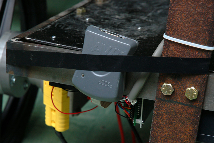
This is how we change the software on the fly. Reaching underneath the vehicle typically results in pain as the spinning motor controller fans collide with our fingers, so this programming module has been run to the outside of the vehicle for easy access. The Atmel ATmega32 does not require us to touch anything on the PCB, such as manually resetting the chip or switching it into any sort of special programming mode, so writing software to it is as easy as connecting a serial cable to this module and pressing "program" in AVR Studio.
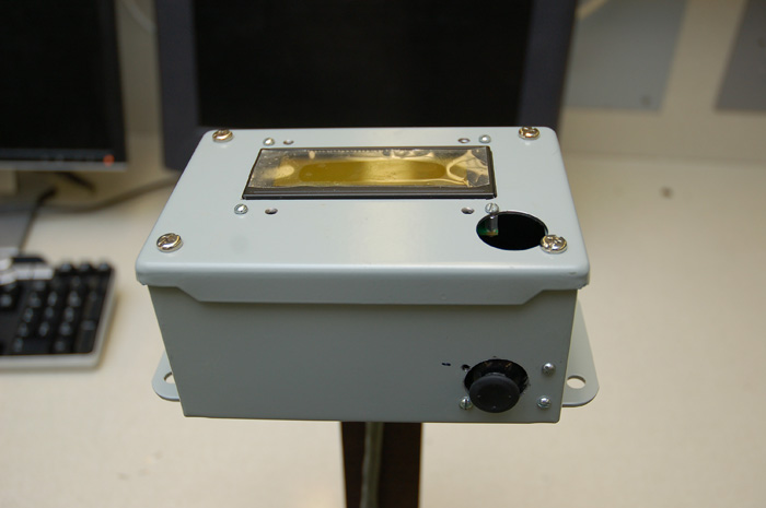
This is the human interface box. It shows the rider a bunch of things like their tilt angle and battery life. This box also contains a joystick for turning.
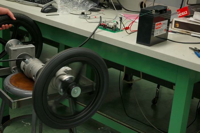
Some initial testing was done on the vehicle using just one motor. This is the test setup used. Note the hot glue and hidden masking tape used to hold our parts on as the thing is tilting. It successfully balanced itself using just one wheel, thus giving it the codename, "The One Wheel Deal." There are no strings in the above picture - it is standing on its own power. It will become unstable if it is left standing on its own for a while, but it will eventually stabilize itself again after it dumps all of our electronics on the floor.
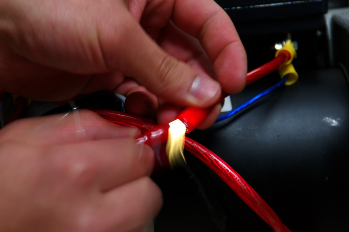
This is what happens when your wires aren't big enough to handle the current. In this case, we accidentally hooked up the battery backwards, which caused a short circuit and some melted wires.
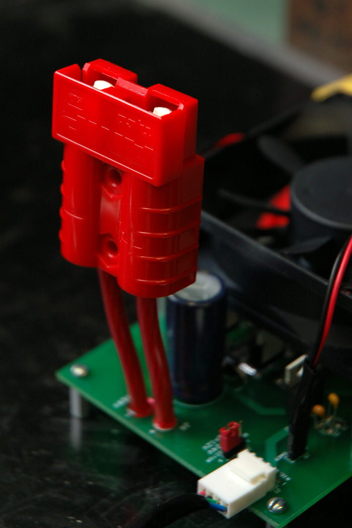
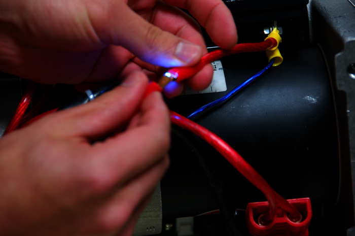
This is one of the beefy connectors being used to connect all of the high current wires together. All of them are polarized and keyed, so that nothing can be hooked up wrong.
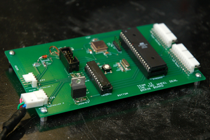
This is the final assembled Brain Board PCB. The two sensors were installed by priming the pads with solder and using a heat gun. The pinout on the accelerometer was all wrong, so some fly wiring had to be done. The pinout for the linear voltage regulator (Orcad's database part is wrong!) was wrong, so this was creatively corrected as seen above.
An initial test setup for the motor controllers was created using one 12V battery, one motor, and a function generator.
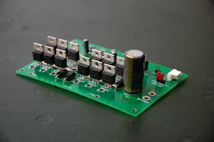
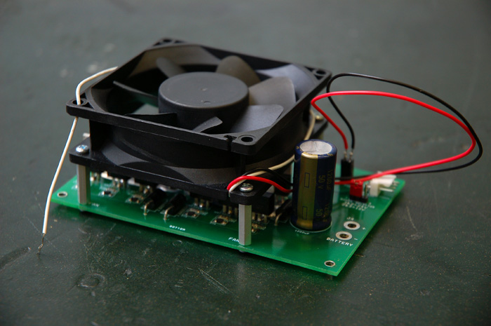
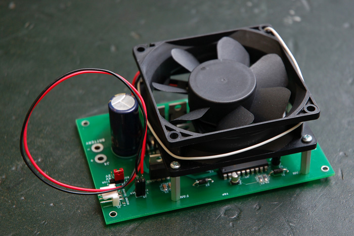
This is the mostly completed motor controller with and without the optional 80mm fan attached.
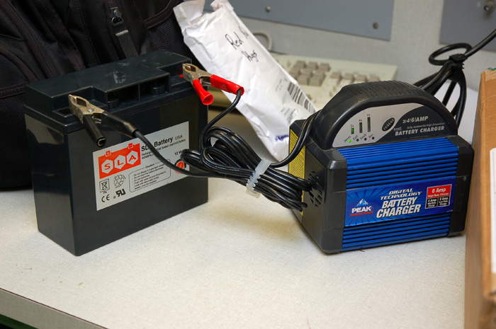
The batteries won't charge themselves...
High pressure tires have been installed to allow The Two Wheel Deal to carry the heavier-than-a-bike payload of the vehicle plus a passenger. The shallow tread depth will minimize the amount of tread squirm experienced, which should make the vehicle slightly more predictable for the control algorithm.
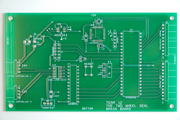
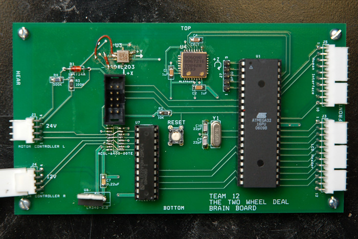
Top side of the Brain Board PCB.
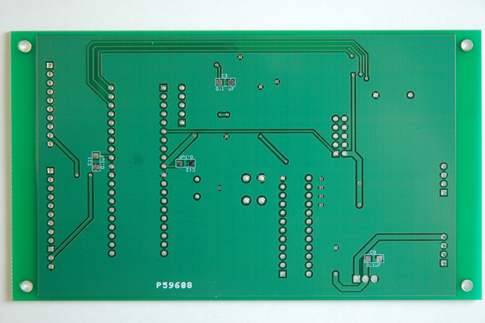
Bottom side. Notice the copper pour in place to reduce EMI.
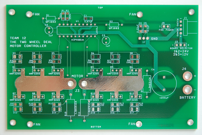
Top side of the Motor Controller PCBs. Take a look at those enormous high current traces!
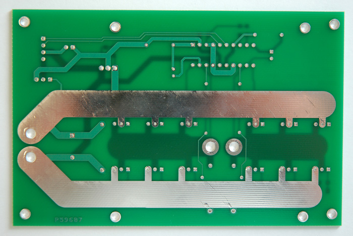
Bottom side. You can almost see yourself in those traces!
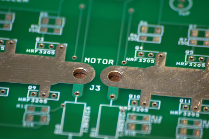
These are the huge vias that will accept 10 gauge wire that will connect the motor controllers to the motors.
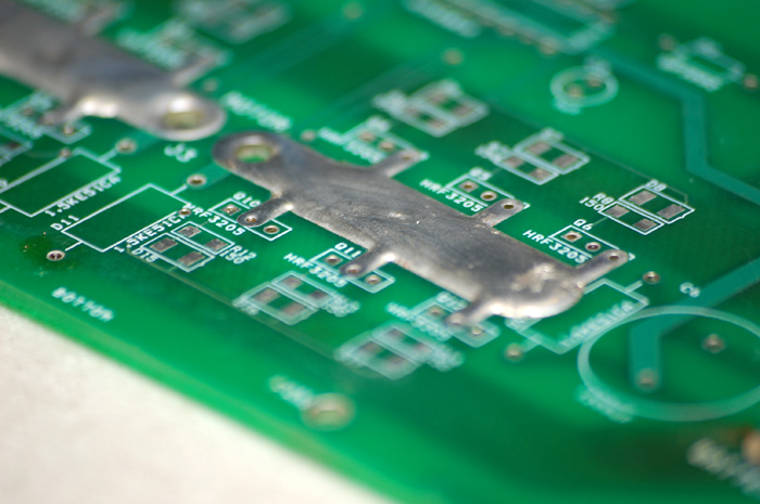
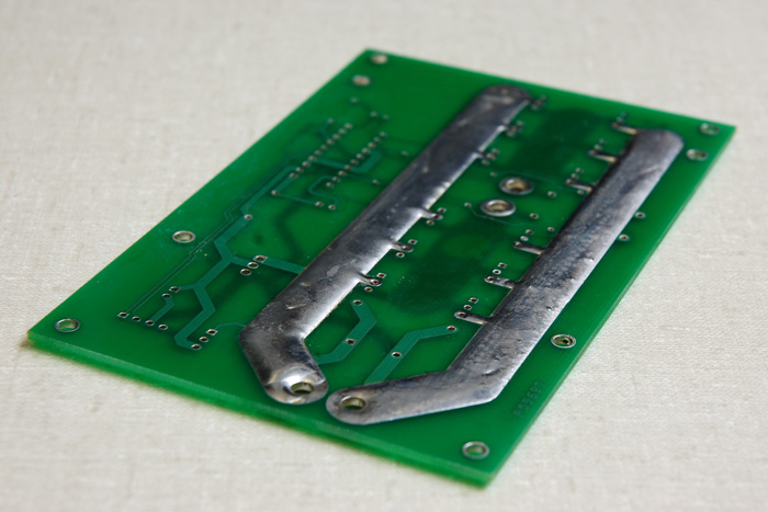
All of the high current traces were beefed up with solder to increase their current capacity. The boards are noticeably heavier after this addition.
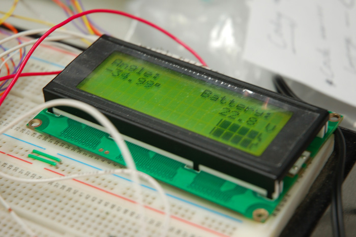
This is a 20x4 LCD that displays information to the user, as well as snide remarks when it knows you're about to bite the dust.
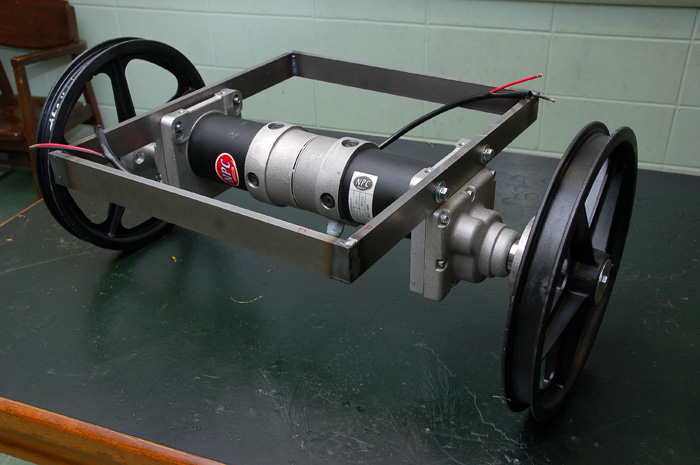
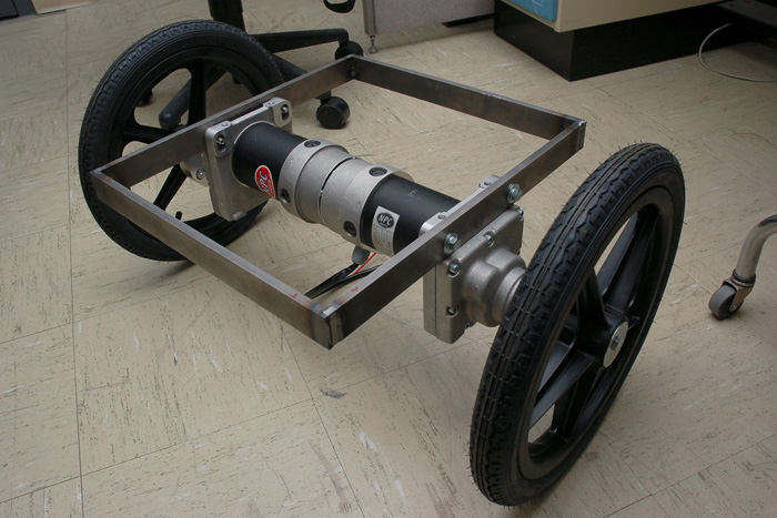
This is the initial assembly of the Two Wheel Deal. The wheels, hubs, frame, and motors are assembled.
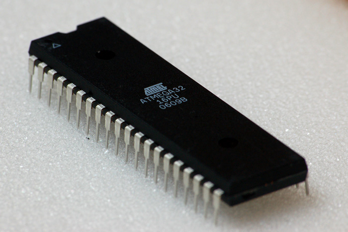
An Atmel ATmega32 40-pin DIP package microcontroller. This should have everything that we need to control The Two Wheel Deal.
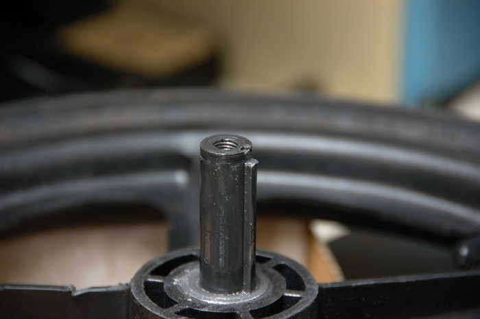
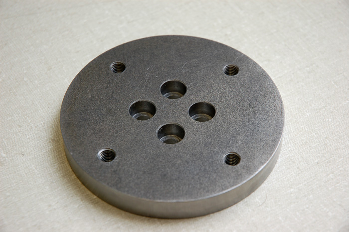
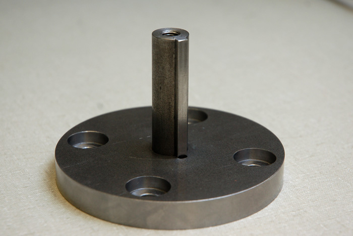
These are custom machined aluminum wheel hub assemblies that allow us to mate our wheels to our motors. Big thanks to Kevin Eccleston, CIMT, who designed and machined these parts using a CNC mill, a lathe, some drills, some saws, and a generous amount of elbow grease.
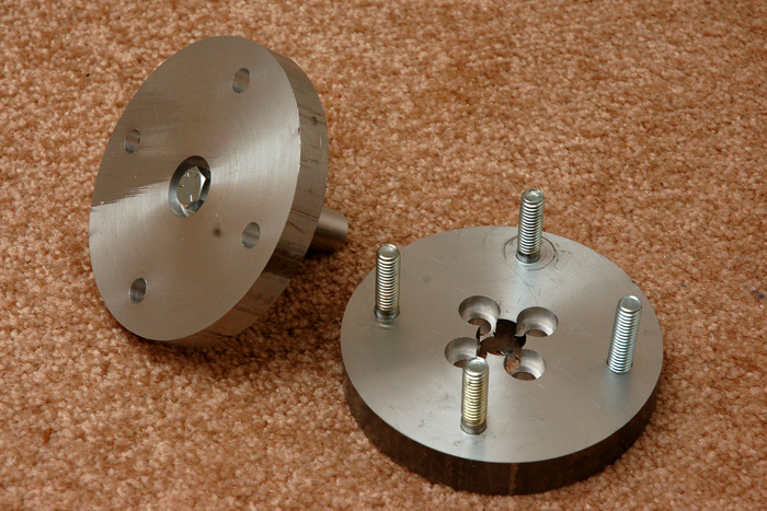
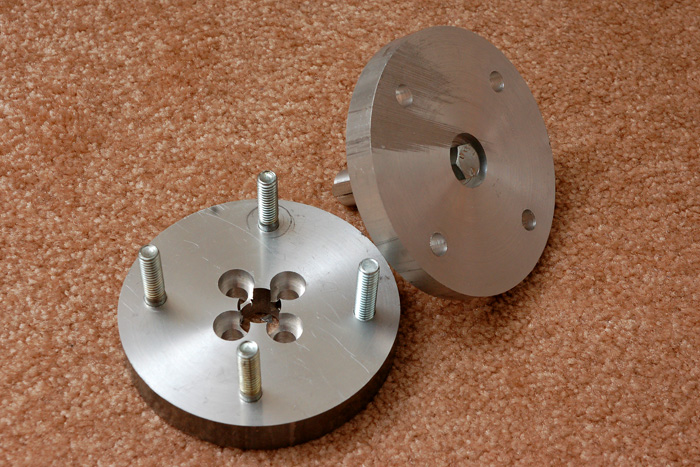
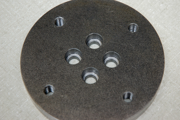
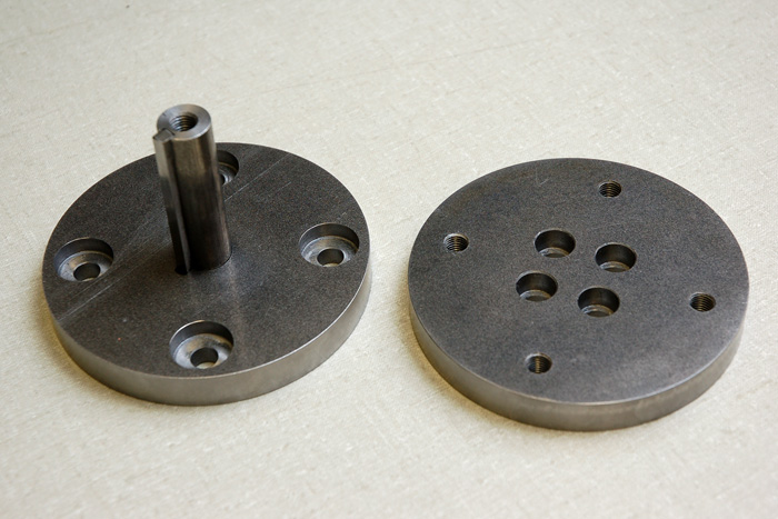
Here are some disassembled shots of the wheel hubs. The metal isn't perfect because we found it in a scrap bin.
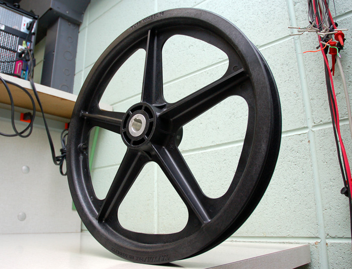
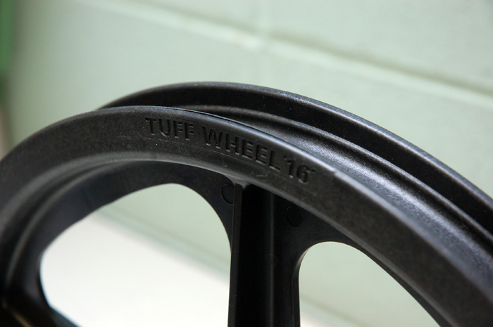
Skyway Machine 16" Tuffwheel - A lightweight plastic wheel used on BMX bikes and high performance childrens' toys. This particular wheel was custom made with a machined keyway so that it can be driven by our motors.
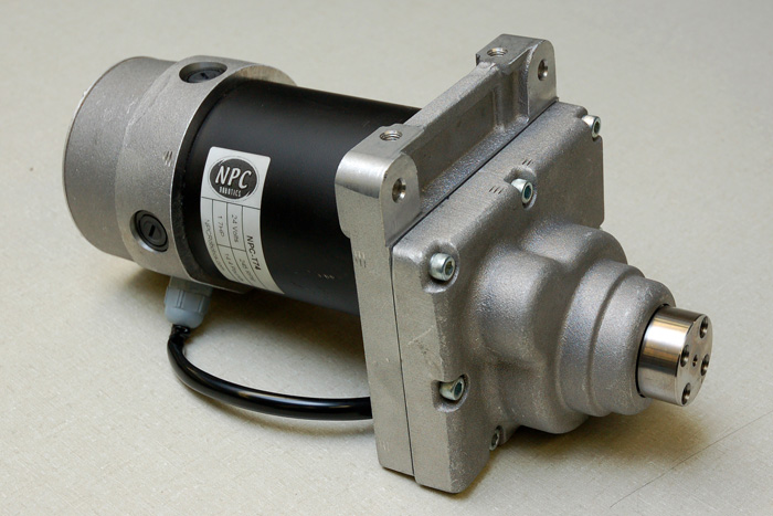
National Power Chair NPC-T74 Motor - A beefy motor that is popular with heavyweight battle bots and wheelchairs (and probably battle wheelchairs). It produces a maximum of 120 ft-lbs of torque at the motor shaft - which is as much or more than the typical economy car engine. This high amount of torque makes it ideal for direct drive applications, but also causes the motor to draw an incredible amount of current - 210 amps if you are able to hold the output shaft still.
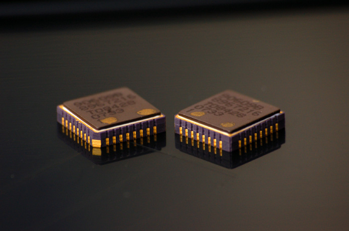
Melexis MLX90609E2 ±150 °/s Angular Rate Sensors. When you twist them around, they will output a voltage proportional to how fast you twist.
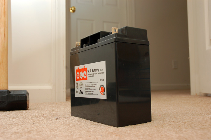
Generic Sealed Lead Acid Battery - 18Ah, 1/2 U1 Size. Typically used in wheelchairs. The manufacturer claims that the "SLA" stands for "Sealed Lead Acid" but I think we all know that it stands for "Segway Look-Alike". The internal resistance of each of these batteries is about 25 mΩ, which in theory means that it will be capable of supplying 1000A to the motors for a very short period of time. The manufacturer claims that it will provide 720A for 5 seconds, and 360A for 30 seconds. Each battery has a capacity of 18 Ah, and with two wired in series, they will give us a total capacity of approximately 36 Ah.