
Greg Eakins' Lab Notebook
Week 01
December 13, 2007(1.0 hour):
Met with team to discuss individual preparation work and research for the project over break. Discussed ordering/sampling parts, microcontroller research, system design considerations, and various other project needs.
January 9, 2008(1.0 hour):
Ordered batteries, 2 12V 18Ah Sealed Lead Acid batteries. These should provide the NPC-T74 motors with ample current at 24V. Contacted a few companies to request samples of accelerometers and angular rate sensors that we will need in our design. Melexis offered to supply us with some angular rate sensors. These sensors look extremely nice, as they have both an analog and an SPI output. Using the SPI would (hopefully) eliminate some filtering and algorithmic work. The major challenge now for this part is to get a breakout board or socket for this surface mount part.
January 10, 2008(1.5 hours):
Met as a team to discuss a project name, define the general scope of the project, write a preliminary project proposal, and set up the website.
WEEK 01 SUMMARY
Accomplishments: Submitted preliminary project proposal.
Found sources for parts and started ordering/sampling.
Weekly Work Total: 3.5 hours
Project Work Total: 3.5 hours
Week 02
January 14, 2008 (3 hours):
Worked on putting website together. Created the top graphic and finished the majority of the CSS.
January 15, 2008 (2.5 hours):
Met as a team after class to work on project presentation for Wednesday and the final proposal due on Friday. Did a significant amount of work on the website.
January 17, 2008 (2.5 hours):
Met as team to do some more in-depth project planning. The motors and batteries have arrived (the most significant parts, size wise), so the first decisions were on the layout and size of the chassis. Decided on putting the batteries between the feet (to act as foot guides), and mounting the motors to the bottom of the chassis, with the wheels connected directly to the motors. The manufacturer of the motors said that the NPC-T74 can withstand an axle load of 200 lbs directly on the axle, putting the total load capacity at a very safe 400 lbs. A closer look at Atmel's microcontrollers reveals that these may be better chips than the PICs. They have a good number of speciality chips, with one of them specializing in motor control. The Lighting AVR line, particularly the AT90PWM316, looks like a good processor for this application due to the precise 16-bit PWM outputs, giving a duty cycle resolution of 0.0015% per bit, which will be very important for a precise motor control algorithm. A PIC was selected originally due to the wide amount of support for it on the internet, but the Atmel has too many impressive advantages for this application.
WEEK 02 SUMMARY
Accomplishments: PSSCs finalized.
Parts arrived/ordered and chassis layout decided on.
Weekly Work Total: 8 hours
Project Work Total: 11.5 hours
Week 03
January 22, 2008 (1 hour):
Met with team to discuss some chassis and PCB layout decisions. Laying out the PCB such that the left and right motor controllers fall on either side of the micro with their MOSFETs hanging off the sides of the board so that they can be screwed to the chassis looks like a good way to increase the current capacity of the motor controllers.
January 23, 2008 (2 hours):
Spent some time doing research on motor controller design considerations and drawing a basic circuit for the motor controllers. The Intersil HIP4081 H-bridge driver will serve as the main commander of the H-bridge. This chip takes care of the high gate voltages of the upper MOSFETs and the delay needed when switching between forward and reverse. Schottky diodes on the gates of the transistors will pull the current away from the MOSFETs when they are turned off to reduce turn off time (and prevent shoot-through due to the large gate capacitance of these huge MOSFETs).
January 24, 2008 (1 hour):
The angular rate sensors have come in from Melexis. Some small prototyping boards will be needed in order to interface to these tiny surface mount parts. Spent some time doing some current calculations on the motors and determining which MOSFETs we should use based on cost, availability, and current handling. Each motor controller will require a peak current handling of over 210 amps (motor draw at 0 RPM and full torque). The Fairchild HRF3205 looks like a decent choice. It is rated at 100A continuous, has a very low on resistance, and is cheaper than most 100 amp MOSFETs at only $1.83 each from Digikey. If 3 of these MOSFETs are put on each leg of the H-bridge and have ample cooling, these motor controllers should be able to continuously handle close to 200 amps each. Though the motor has a peak current draw of 210 amps, the current estimations are extremely conservative, as there should never be a situation where a motor is pulling the full 210 amps for more than an instant. Once the full current is applied to the motor, over 100 ft-lbs of torque is applied to the wheels, which is far more than enough to get some rotation. Once rotating, the current draw of the motors decreases. The duty cycle of the pulse width modulated current should be far less than 100% since the required torque will (hopefully) be far less than the maximum output of the motors.
WEEK 03 SUMMARY
Accomplishments: Motor controller design started.
Chassis build started.
Weekly Work Total: 4 hours
Project Work Total: 15.5 hours
Week 04
January 29, 2008(5 hours):
Met with group and did some rough number crunching to determine the required torque of our motors given our design constraints. Ideally, this vehicle should be able to recover from a tilt of 10?either way at the maximum speed of 15 mph. The crude calculations indicate that the NPC-T74 does indeed meet this specification, with a comfortable working margin.
The internal resistance of the sealed lead acid batteries is 12 milliohms. This gives a theoretical short circuit current of 1000A. This would, of course, be for a very short period of time. This value seems to agree with the spec sheets on similar batteries, which say that they can deliver about 720A for 5 seconds.
Did some further research into microcontrollers and determined that the ATmega32 might be a very good micro to use in this design. After some research, it seems that this micro controller's 16-bit timer module is capable of outputting two 16-bit PWM signals of the same frequency (and hopefully of different duty cycles). It also comes in a DIP package, making it very easy to work with when prototyping.
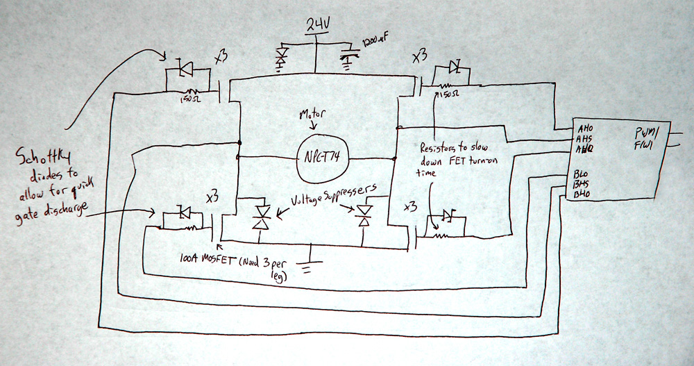
January 31, 2008 (11.5 hours):
The majority of the H-bridge parts are on their way from Digikey (MOSFETs, diodes, resistors, capacitors, voltage regulator). Samples of Intersil's HIP4081AIP full bridge FET driver and two Atmel ATmega32 microcontrollers are on the way as well. Met with team to discuss some lose ends on parts decisions such as a steering mechanism and a passenger detection mechanism. A joystick from a broken XBox controller is a possibility for steering. Here is a rough sketch of the motor controller:
WEEK 04 SUMMARY
Accomplishments: Ordered the majority of the needed parts, determined some basic performance goals, completed design constraint homework, sketched basic motor controller circuit
Weekly Work Total: 16.5 hours
Project Work Total: 32 hours
Week 05
February 4, 2008(1 hour):
Created a rough CAD model of The Two Wheel Deal. Here are some pictures. The batteries are in black, the motors are in red, and the motor controllers are in green.


February 5, 2008(4 hours):
Drafted the motor controller circuit in OrCAD. Upon closer inspection, the HIP4081A FET driver has seperate PWM inputs for forward and reverse. This means that the single PWM signal coming from the microcontroller will need to be switched between the inputs using some kind of simple logic in order to change direction. A small PLD may be added the the circuit to perform this task for both motors.
February 7, 2008(2 hours):
Researched connectors for the motor controller board. Tyco makes some solid looking multi-geneder high current battery connectors that look ideal for this application. One problem that has come up is that the PCBs for this class have a maximum trace thickness of 1 oz. To handle the amount of current flowing through these boards while maintaining a minimal trace width, the traces need to be at least 4 oz thick. This means that either fly wires will need to be added or no-solder-mask zones will have to be put in place so that solder can be added to increase the current capacity of the traces.
February 8, 2008(2 hours):
Researched and ordered headers and connectors for the motor controller boards and the microcontroller board.
February 10, 2008(3 hours):
Drafted schematics for the microcontroller and sensor circuit. A 16MHz external oscillator will be used to clock the microcontroller instead of the 1MHz internal RC oscillator. While this may not be necessary, it is better to have the processor running a little bit faster than it needs to be.
WEEK 05 SUMMARY
Accomplishments:
Drafted CAD model of chassis.
Completed first draft of motor controller schematics.
Started on microcontroller and sensor board schematic.
Weekly Work Total: 12 hours
Project Work Total: 44 hours
Week 06
February 12, 2008(8 hours):
Finished microcontroller board and motor controller schematics. Decided to add the Vref output of the angular rate sensor as an input to the ATD. The Vref output represents the sensor's 0?s voltage. This can be compared to the value measured on the sensor's output to increase the accuracy of the reading. The schematics pass all design rules checks. Did some hub design work with an MET student. He drew of rough sketch, shown below, of the piece that will bolt directly to the shaft of the motor. A second piece will be used to bolt the wheel to this hub. The countersinking of the bolts will allow for flush mounting of the second piece. The main problem now is obtaining raw materials.

February 14, 2008(6.5 hours):
Spent some time designing and modeling a hub to mate the 16" Skyway wheels to the NPC-T74 motors. The design is a 3 piece design due to some conflicts between the mounting bolts that mount the hub to the motor and the shaft that actually goes through the wheel. Finished up the schematic for the brain board by adding a 10-pin connector for programming the Atmel chip in-circuit. This is a very nice feature of the Atmel, in that it can be programmed through the SPI with only 4 pins - SCK, MOSI, MISO, and RST. This will be done through the AVR-1 Atmel development board in the lab.
February 15, 2008(5 hours):
Started the process of assigning parts to their appropriate footprints on the brain board and did some planning on how best to arrange the motor controller circuit board.
February 16, 2008(13 hours):
Created an initial draft of the brain board PCB layout. All signals are routed, but a ground and power plane need to be added to make all of the ground and power connections. Custom footprints had to be made for the accelerometer, angular rate sensor, crystal, and reset switch.
WEEK 06 SUMMARY
Accomplishments:
Completed plans for wheel hub design.
Completed first draft of brain board PCB design.
Weekly Work Total: 32.5 hours
Project Work Total: 76.5 hours
Week 07
February 17, 2008(6 hours):
Routed power and ground on the Brain Board. All power and ground traces are enlarged, with a size range of anywhere between 0.018 and 0.050 inches, depending on the needs of the attached part. A ground plane was added for noise and to make sure that all parts have a solid ground connection. One problem that became apparent was that the default part for the PAL22V10 has its power pin already defined as VCC. This is a problem because the power on the brain board is labeled as +5V - a separate net. Without knowledge on how to combine these nets, the VCC pin was manually routed to +5V in the layout. The design passed all design checks, and the silk screen was cleaned up and labels added to the board for documentation.
February 18, 2008(4 hours):
Had the hub shafts and keyways machined for the wheels.
February 19, 2008(6 hours):
Finished a preliminary draft of the motor controllers. As of now, the high current traces are only 100 mil wide. The traces will need to be made wider (and perhaps rerouted). If the main traces were widened to 400 mil, and then thickened up to 12 mil tall with solder (this is approximately equivalent to 8 oz copper traces) after the board arrives, the traces could handle 70 amps continuously with a temperature increase of 20°C.
February 23, 2008(7 hours):
Purchased all of the hardware for assembling the wheel hubs and the motors. The hubs use 5/16"-24 cap screws to attach to the motor shafts. The screws are counterbored into the hub so that the second piece of the hub can fit flush with the surface of the first part. The second part of the hub holds the keyed wheel shaft, which is assembled using 5/16"-24 hex bolts, with the fine thread being for strength. The motors (with the wheel assembly) were tested at 12V using the battery. They appear to pull a great deal more current than they did without the load of the wheel, which was evidenced by the large amount of arcing.
The motor controller PCB boards were finished up. The high current traces were widened up to 300 mil all around. If these traces are thickened to about 0.021" (equivalent to about 15 oz copper traces) with solder, they should be able to continuously handle 50 amps of current. Large vias were place on the motor controller boards to facilitate the attachment of 10 gauge wire to the board from the battery and to the motors. These vias have a drill size of about 120 mil, and a width of about 200 mil. Several components were moved around to optimize the trace lengths and many other traces were enlarged. The final step now is to place a copper pour on the board.
A good point was brought up during Jeremy's presentation on Wednesday. The tabs on the FETs are electrical connections - and connecting the tabs of all of the FETs to the chassis for cooling would result in massive shorting and very fast destruction of our FETs. The proposed solution to this is to find some ceramic insulation to insulate the upper FETs from the chassis.
WEEK 07 SUMMARY
Accomplishments:
Completed second draft of motor controller PCB.
Built custom wheel hubs.
Assembled the rolling chassis - frame, wheels, and motors.
Completed motor controller PCBs and merged all PCBs into one file.
Weekly Work Total: 23 hours
Project Work Total: 99.5 hours
Week 08
February 25, 2008(2 hours):
Met as team to split of the formal design review presentation. Ordered some 10 gauge power wire (sold as automotive amplifier power wire) and some eyelets for wiring up the batteries and motors on the vehicle. Put some finishing touches on the motor controllers to make sure they are presentable.
February 26, 2008(6 hours):
Met as team to work on completing the design review presentation. During the design review, a few good points were brought up regarding the PCB and electrical design. The microcontroller does not have a bypass capacitor between VCC and ground. This was left out largely because most hobbyist using the AVR microcontrollers leave them off, but for improved noise performance, a 100nF bypass capacitor will be added to the design.
A second issue regarding protection of the ATD channels was brought up. The voltage divider circuit for the ATD is run straight into the microcontroller. It was suggested that a zener diode be added between the analog input and ground to clip off any voltage spikes that may (and probably will) occur.
The motor controllers were a hot topic. A combination of design considerations were brought up that resulted in a complete overhaul of the motor controller boards. First of all, Professor Meyer's thoughts on the exact power dissipation of the FETs, based purely on the on-resistance, led to some number crunching to see if the amount of power dissipated by the FETs is low enough to run on air cooling alone. The FETs each have an on resistance of 8mΩ and assuming that the motors typically draw about 50 amps of current continuously, the power dissipated by each transistor (divided amongst the three), would be about 2.2 watts, which is low enough for air cooling. This means that the edge-based board layout is not necessary and a much simpler layout could be put together. This layout would avoid the current loop created by the edge based layout of the transistors, and it would also serve to shorten the high current paths and allow for wider traces.
February 27, 2008(6 hours):
After much thought, a new board layout for the motor controllers was proposed. This new layout had three goals:
1. Rearrange the MOSFETs to minimize current paths.
2. Consolidate the two (left and right) motor controller PCBs into a single design (but still two boards).
3. Arrange the circuit such that the operation is visually intuitive.
The new PCB was redesigned from scratch, and completely placed and routed. The new PCB has the MOSFETs arranged much as they are in the schematic. FETs that share a leg are aligned such that, if needed, a heatsink can be added across each trio. Mounting holes have been added to the board for the optional installation of an 80mm computer CPU fan, the most common size of fan found in computers. This fan will be added only if needed. The PCB presented in the previous presentations was a combined board that consisted of all 3 boards combined into one due to the single board restriction. Chuck Barnett let us know that this was not necessary, and that he would allow the three boards to be printed separately. This greatly simplifies the development of the boards, and one interesting change to the implementation resulted. The motor controllers, previously built as a left and a right, each with a separate schematic and PCB layout, have been cleverly combined into a single board. The only difference between the two boards was that one had 12V running to the micro, and one had 24V. The two boards have been combined into a single board by routing both 24V and 12V to a 3-pin header, where a simple shunt will be placed across the appropriate pins to connect either net to the output pin on the header leading to the microcontroller board. This will simplify debugging, since both boards will be essentially the same, and simplify development, since only a single schematic and a single PCB layout is needed.
February 28, 2008(5 hours):
The fan holes were placed on the motor controller boards and all of the part footprints were double checked and changed as needed. The silkscreen was cleaned up and all important or unique parts labeled. Here is a comparison of the new board to the old:


March 1, 2008(4 hour):
Started working on a more detailed model in Google SketchUp. This one better reflects the new battery placement.


WEEK 08 SUMMARY
Accomplishments:
Redesigned motor controller PCBs.
- Combined motor controller boards into one reusable design.
- Eliminated current loop.
- Enlarged all high current traces.
Updated microcontroller board with bypass capacitors and a zener diode on the battery meter.
Started a new CAD design of the vehicle.
Weekly Work Total: 23 hours
Project Work Total: 122.5 hours
Week 09
March 3, 2008(1 hour):
Purchased 1N4734A 5.6V Zener diode to use to protect the battery meter ADC channel. This diode will short anything above 5.6V to ground, which should only be voltage spikes coming from the motors on the 24V rail. A bypass capacitor was added to the VCC pin of the microcontroller, and the PCB was updated to reflect the new changes.
March 4, 2008(4 hours):
Added a 2-pin 12V fan power connector to the motor controller boards for the optional 80mm cooling fan. The typical computer case fan draws less than 0.2A, and the 12V LM34 series voltage regulators are able to supply 1A. Since the rest of the 12V line will require less than 100mA, very little additional strain will be put on the regulators. The additional cooling provided by the fan should negate any additional heating of the parts.
The soldermask was removed from the high current traces. This was done by adding obstacles to the SMT and SMB layers in Orcad Layout that are in the same place as the traces.
All Gerber files were submitted to the FreeDFM manufacturability checking service and they passed with no show stoppers and only minor adjustments to the soldermask and silkscreen.
March 5, 2008(6 hours):
Worked on compiling a bill of materials and did a proof of parts on all of the major components. Chuck set up a high-current testing station for testing the motors and motor controllers. When connected directly to the battery and with no load, the NPC-T74 motors draw 5 amps each. Given a small load, it is not difficult to increase the consumption to 20 amps or more.
March 6, 2008(6 hours):
Finalized the PCBs and added a few finishing touches. General I/O pins 1-5 on the microcontroller were pinned out through a header just in case extra I/O is needed in the future. The RS pin on the LCD display was moved to pin 20 (PD6) from pin 33 (PA7/ADC7) in order to reserve the entire Port A for inputs - either logical or ADC. This will also move the RS signal to the same port (Port D) as the LCD clock signal, E. A copper pour attached to the GND net was added to the micro board to reduce EMI, which should help clean up the signals coming from the sensors. The Gerber files for both the motor controllers and the brain board were checked again for problems and submitted for manufacturing.
Some problems came up when attempting to read the ADC channels on the microcontroller. The ADC channel read in software and the channel read in hardware were not matching up. In other words, the value on pin ADC1 was appearing on the ADC2 register. This was due in part to the program driven implementation of the A/D conversion. The program would initiate the ADC conversion and then poll a flag indicating that the ADC was done converting. For some reason, the conversions were happening too fast and overlapping one another. The ADC routine was changed entirely to an interrupt driven program where the ADC module calls an ISR every time a conversion completes, and the ISR starts the next conversion after storing the result in an array. The main program never touches the ADC channels. Instead, if the current value of the ADC is needed, the array of ADC values is read. This greatly improves the reliability of the system. The ADC clock is the system clock (16MHz) divided down by 128, which works out to an effective ADC clock of about 125kHz. Slowing down the ADC clock by the maximum amount helps with noise on the ADC channels. Since a single converter is multiplexed among the pins, the effective clock speed for each pin is 25kHz (assuming that 5 channels are used). Each conversion takes 13 clock cycles, meaning that the ADC will complete a conversion on every output about 2000 times per second, which is plenty quick for this application (only 100 times a second is needed). The additional samples will likely be used for filtering. The output of the LCD was cleaned up by changing the binary output to a decimal output. sprintf was used to painlessly implement the conversion of the internal numbers to characters for the LCD. All of the code used in the program so far uses only 4% of the total memory (32k) on the ATmega32. The Atmel C compiler (gcc) seems extremely good at optimizing the code even when large libraries such as stdio.h and math.h are included.
March 7, 2008(1 hour):
Met as team to discuss work for Eric to do over break. AVR Studio appears to be broken at the moment, as it will not compile the code. Pete and Eric created a working tilt angle meter by using the arctangent function on the two axis accelerometer. One issue that has not been a problem is the output impedance of the Analog Devices accelerometer. Team 14 is using essentially the same accelerometer with an amplifier (with a gain of 1) between the sensor and the microcontroller ADC port. The thought is that the ADC ports will be unable to read from a sensor with such a high impedance. The implementation used on The Two Wheel Deal does not use an amplifier - the accelerometer is connected directly to the ADC ports. All testing done thus far has been successful, and no problems have been encountered, though this will be a point to remember if strange problems creep up later on.
WEEK 09 SUMMARY
Accomplishments:
Made several hardware changes:
- Added zener diode to battery level detection circuit to protect micro.
- Added a bypass capacitor to the microcontroller's VCC.
- Reassigned a pin on the microcontroller to allow more logical access in software.
- Added a ground plane to the bottom layer of the microcontroller board to reduce EMI.
- Added header that connects to several unused general purpose I/O pins on the micro.
- Added a 12V power connector to the motor controller boards to power the optional fan.
- Removed soldermask from the high current traces on the motor controllers.
Wrote and tested interrupt driven ADC routine.
Compiled nearly complete bill of materials with prices and quantities.
Submitted final PCBs to Chuck.
Weekly Work Total: 18 hours
Project Work Total: 140.5 hours
Week 10
March 18, 2008(2 hours):
Added a battery level algorithm to the software. The battery algorithm works to provide Eric's battery information display with a heavily filtered value for the battery. It works by sampling the battery value from the ADC every time it is called and averaging it with the last 60 samples collected. Since this routine is called once every second, the filter will be over a 1 minute time span. This should eliminate any false low readings caused by high current draw from the motor controllers. AVR Studio had some major issues handling floats and converting between integers and floating point numbers. In C, a simple assignment should be allowed to convert between the two, instead, AVR Studio was refusing to compile the program. This was fixed by linking the project with the liba.m library. Apparently floating point support is not inherent on to conserve memory space. This library was added by going to Project -> Configuration -> Libraries.
March 19, 2008(5 hours):
PCBs came in today. Started work on the motor controllers by beefing up their high current traces with solder. A huge amount of solder was added and all flux was cleaned up. One board warped slightly from all of the heat, and the solder mask was burned in one spot. Began population of the board, starting out by adding the 12V voltage regulator. It turns out that the footprint for the LM34xx series regulators was wrong, so some leads were switched around to remedy the problem. Next, the FET driver and all of its auxiliary components were added along with the 1200uF capacitor, and 1 MOSFET on each leg of the H-bridge. The circuit was tested using a 20V power supply, a function generator, and an oscilloscope. The circuit seemed to work by outputting the 20V PWM signal of the same frequency as the input signal. This was, of course, with no current at all. The oscilloscope, for some reason, would not read a negative PWM signal, which caused some headache when trying to figure out why the circuit was arcing when probed. Below is a picture of the initial assembly.

March 20, 2008(7 hours):
Fully assembled and tested the motor controller PCBs. During assembly, the clearances for several of the through hole components were too tight to easily fit the parts through. The most problematic parts were the MOSFETs and the TVS diodes. In order to get the parts in, many of the vias needed to be heated up, and the parts pursuaded with a pair of pliers. Another problem encountered is there are no 1206 capacitors large enough to fit in some of the capacitor spots on the board. Instead, either the surface mount electrolytic capacitors or ceramic through-hole capacitors were used for the values larger than about 0.05uF.
The completed PCBs were tested using a 12V battery, a function generator, and an oscilloscope. As a side note: even though the linear regulator needs more than 12V to output 12V to the FET driver, the FET driver is very robust and able to run on a wide range of voltages (which should help if battery voltages temporarily drop below 12V). Once a PWM signal of the correct frequency and duty cycle was confirmed on the osciloscope, the motor controllers were hooked up to a motor. The controllers worked fantastically well. The controller responded to variation in duty cycle as well as variation in direction. One important change made was in the operating frequency of the motor controllers. 2 kHz was initially chosen in order to minimize switching losses in the circuit. When this frequency was used, a highly audible and very irritating tone was emitted by the motors, so this frequency was raised to 15 kHz in order to eliminate the noise. Pete came up with the idea of using a low operating frequency as a low battery warning. No loss in performance would be experienced, but the rider would definitely know when the batteries were getting low. The FETs did not heat up at all during this testing, however, the measured current was only 5 amps in this unloaded state, so the current handling ability of these motor controllers is still a question that has yet to be answered. It should also be noted that the duty cycle of the signal sent to the motors is the inverse of the PWM signal coming into the motor controller. This will have to be compensated for in the program logic or PLD logic. Once testing was completed, the 80mm fans were installed on both motor controllers as seen in the picture below.


March 21, 2008(5 hours):
Completed the motor controllers by soldering in the 10 gauge wires and installing the high current Tyco connectors to allow them to be easily disconnected from the motors or batteries as needed. The motor leads come out of the bottom of the PCB so that the wires do not have to squeeze between the potentially hot MOSFETs on the top. Some test PWM routines for the microcontroller were written and tested on the motors using the motor controllers. So far, the motor controllers have shown no issues controlling the motors, even when commanded to suddenly reverse from full speed. They now have a total of about 4 hours of testing time on them with no issues.
WEEK 10 SUMMARY
Accomplishments:
Software:
- Wrote battery level filtering algorithm.
- Figured how to add floating point support to the microcontroller.
PCBs:
- Thickened all high current traces on the motor controllers with solder.
- Fully populated motor controller boards.
- Added the 80mm fans and the 2-pin power connectors.
- Installed high current Tyco connectors with 10 gauge wire on the motor controller boards.
- Performed preliminary testing on the motor controllers using signals from the microcontroller board and achieved control of the motors.
Weekly Work Total: 19 hours
Project Work Total: 159.5 hours
Week 11
March 24, 2008(5 hours):
Wrote a PWM control function that takes an input from [-1000,1000], corresponding to the duty cycle and the direction of the PWM output. It automatically modifies the direction output and the duty cycle register based on this input.
Did some work on deciding how the chassis would be built and laid out. Jeremy found a length of metal that should work as the upright post. This post will be mounted onto the vehicle such that it hangs down below the level of the battery and Brain Board PCB. This should provide both some protection from the ground when the vehicle tips over.
March 25, 2008(3 hours):
Had some holes drilled and tapped for the upright handlebar post. Decided on a new battery mounting design that involves no brackets at all. Rubber (or other friction material) will be inserted on both sides of the battery. A 5/16" bolt will be threaded through the sides of the vehicle to clamp the battery in place. Angle aluminum (L-shaped) will be used to prevent side-to-side motion of the batteries.
March 26, 2008(2 hours):
Did some testing and some modification to the PWM algorithm so that it would work on both channels. Also searched for some scrap metal to use for battery brackets.
March 27, 2008(4 hours):
Wrote a basic PD-algorithm that uses the value from the angle (calculated from the accelerometer x and y axes) and the angular rate sensor to calculate an incremental change in the PWM duty cycle. The formula used is as follows:
leftmotortorque += Kp * (tilt_angle - rest_angle) + Kd * gyro
By incrementing or decrementing the motor torque based on this formula every 1/100 of a second, smooth changes in the PWM duty cycle are achieved. An oscilloscope was used to verify that the output to the left motor controller was working correctly. By tilting and observing the outputs, the appropriate PWM output and transition between forward and reverse was observed. One goal of this development was to ensure that the PWM transitioned smoothly from a 0 demand (0% duty cycle) on the forward pin to a 0% duty cycle on the reverse pin. If this did not happen, the vehicle could buck and kick, saturate the sensors, and then become unstable. Initial testing was done on one motor with the vehicle sitting on a chair with the wheels off the ground so that incorrect rotation of the wheels would not lead to a disaster. From here, it was just a modification of the signs and the gains (Kp and Kd of the PD controller) to get the response to tilting of the PCB within a reasonable magnitude.
On the chassis, the handlebars were fabricated by cutting off a 16" piece of tubing that Eric brought in. It was sandblasted with a nice textured finish for maximum grip.
March 28, 2008(4 hours):
After a sufficient amount of testing was done on the control algorithm with the wheels off of the ground, the vehicle was placed on the ground to observe its behavior (with only one wheel powered). On the first trial, with Kp = 0.5 and Kd = 2, the vehicle would follow the tilt of the handle bars, but would not balance on its own. The parameters were experimented with until the vehicle would indeed balance itself for a few seconds before becoming unstable. The final values for Kp and Kd for the one wheel testing @ 12V were Kp = 1.3 and Kd = 4.5. Wrote a quick filtering algorithm that filters the accelerometer and gyro values over 1/100 of a second, sampling every 1 ms. This smoothes out some of the jumpiness observed in the vehicle's balancing behavior. On the chassis, the human interface box was milled out for the LCD and the joystick, but there are some problems with fitting both parts in the box. Some pictures of the vehicle balancing on its own are below.


March 29, 2008(1 hour):
Took some pictures of the vehicle balancing with one wheel and dubbed it, "The One Wheel Deal". Performed some unintentional testing on the reverse voltage behavior of the circuit, and it appears as if the circuit has some reverse voltage protection built into the motor controllers. It simply shorted out the battery and instantly cooked the small wires that were hooked up. The circuit functioned correctly after the polarity of the wires was corrected. The reason for the reverse voltage protection lies in the MOSFETs, which automatically conduct when hooked up in reverse to protect the FETs, and also protects the rest of the circuit. The source to drain (reverse) current handling capacity of each FET is 100 A according to the data sheet.


WEEK 11 SUMMARY
Accomplishments:
Software:
- Completed a basic balancing algorithm.
- Determined correct polarity of all compensation.
- Determined ballpark values for the control gains.
Chassis:
- Built handlebar and handlebar shaft.
- Milled rectangle for LCD and joystick.
- Designed battery brackets and submitted them for fabrication.
Debugging:
- Successfully balanced the vehicle using only one motor.
- Tested immunity to reverse voltage.
Weekly Work Total: 19 hours
Project Work Total: 178.5 hours
Week 12
April 1, 2008(7 hours):
Finished building the chassis with the new parts made by Chuck in the machine shop. The entire motor and battery part of the vehicle was assembled with very few problems. The brain board was oriented such that the LCD and general I/O ports are facing the front, and both of the sensors are oriented in the proper direction. The front shaft was designed such that about 4" sticks down from the top. This is to provide protection to the front battery and the brain board in case of a tip over. Some initial testing was done on the control algorithm. The gains used earlier to balance the vehicle on one wheel were far too high to be usable with a person riding and with two wheels. Even the slightest movement would result in a huge correction that would result in instability and a forceful removal of the rider. To correct this, the derivative gain was drastically reduced to about 1/8 of its value without a rider. After a significant amount of tuning, the vehicle became somewhat ridable and the whole team learned how to balance it within a few minutes. Today marks the maiden voyage of The Two Wheel Deal. One weakness found so far is in the hubs. The wheels are beginning to develop some free play in them. The aluminum might be too soft to handle the torque applied to them.

April 2, 2008(4 hours):
Began working on the final wiring for the human interface box. The wiring for the LCD was completely redone and all of the connectors were hooked up. A 25 conductor bundle of wires was used to connect the human interface box to the micro controller board. The steering joystick (from an old XBox controller) was installed using a bit of prototyping PCB and some standoffs. The joystick makes some contact with the standoffs, preventing full range of motion, but it can be compensated for in software or safely ignored. A quick and dirty steering algorithm was written along with a filter for the steering values, but it works poorly. The algorithm basically takes the value read from the joystick, subtracts the offset, and then multiplies by a gain. The problem is that the response of the motors is nonlinear around 0 torque. This means that at standstill, the joystick can be moved quite far before any movement starts, and once it starts, the demand is already quite high. Testing halted when one of the wheel hubs gave way. The key in one of the hub shafts tore up the aluminum wheel hub, causing the wheel to spin freely. It has become obvious that the aluminum is just far too soft to handle the amount of force put on them in this project. Eric is going to attempt to have the hubs remade out of steel over the weekend.
One issue that was repaired today was the battery meter. The battery gauge was showing 0V, and when traced down with the DMM, no voltage was coming off of the right motor controller (the one that is to supply the 24V signal to the brain board). Some investigation revealed that the trace going from the 24V pin to the 24V rail had burned up. This was soldered back up and the battery meter works. The cause of this issue has not been determined.
April 3, 2008(4 hours):
Did some more work on the steering algorithm. Jeremy and Eric had some trouble mounting the joystick, so the full range of motion is not avaiable. The joystick turns further in one direction than the other. To make up for this, the joystick's value when turning in the further direction has been scaled down such that it matches the range of the other joystick. The turning speed in either direction should be approximatley the same. There is also a problem with the joystick's center. There is some free play in the joystick, which causes a variable zero turning point. To correct this, the value of the joystick value when the vehicle is first started up is read and stored as the center point. This is somewhat dangerous if the user holds the joystick to one side when the vehicle is powered up, as it would begin spinning as soon as they released the joystick. There will be a warning in the user manual instructing the user not to touch the joystick during startup. There is still some roughness in the turning algorithm due to the nonlinear response of the motors at low speeds, but the result might still be acceptable. Velocity compensation is the next thing on the list and will be implemented as soon as new hubs are made.

April 4, 2008(3 hours):
Added some connections to the microcontroller to allow for additions to be made to the human interface box. All of the "Human Interface" (J5) connections have been wired up to free pins on the micro. Pin 3 of J5 was wired to the free ADC channel, ADC7, and all of the other pins were wired to PB0-PB4, giving us a total of 2 free ADC inputs and 5 free digital inputs. The ADC inputs will be used for dynamic tuning of the gain constants on the vehicle, while the free digital inputs will be used for kill switches and other features.
WEEK 12 SUMMARY
Accomplishments:
Chassis:
- Battery brackets were machined and installed.
- All PCBs were mounted.
- Verticle bar mounted.
Software:
- Completed basic steering algorithm.
Electrical:
- Initial wiring completed for power lines and signal lines.
- Wired up unused pins on microcontroller and human interface header.
Completed first ride of The Two Wheel Deal.
Weekly Work Total: 18 hours
Project Work Total: 196.5 hours
Week 13
April 7, 2008(2 hours):
Some issues with the vehicle have crept up over the weekend. The left motor is no longer working when it should. The issue was traced back to the microcontroller. The PWM signal is not showing up on one of the pins, and therefore, not getting to the motor controller. The microcontroller may need to be replaced. A second issue that arose was that the power to the microcontroller board from the motor controller was not reliable, which made the unit difficult to program. This was traced to bad connections in the 4-pin wire harness. These were taken apart and soldered to ensure a good connection.
April 8, 2008(4 hours):
Eric brought the new wheel hubs in and they were promptly installed, though, with some issues. The wheel shaft and key were machined to extremely precise tolerances, and they ended up being the same size as the hub in the wheel. This means that there was 0 clearance, and they could not be pushed on. Instead, they were pressed on in the machine shop by Chuck. The new wheel hubs are threaded on one side, eliminating the need for an opposing nut.
The electrical issues that were found on Monday were solved. It turns out that the PLD burned up for the second time. The lack of optical isolator is becoming a problem, not from the noise and voltage spikes from the motor, but the voltage spikes associated with hooking things up.
April 9, 2008(2 hours):
Wired up two potentiometers so that the control gains, KP and KD, could be varied without having to reprogram the vehicle. The code for both was written such that the values for KP and KD can be varied between 0.00 and 2.00. An impressively good and rather tame set of parameters was found through trial and error that works for both balancing on its own and balancing a person. The general procedure for determining the gains was as follows:
1.Increase KP until the vehicle (balancing by itself) began to oscillate, then tune it back down a bit.
2. Increase KD until the vehicle became unstable, then dial it back down a little.
The vehicle is now 100% ridable and comfortable to ride with just a few minutes of practice. The Two Wheel Deal is nearing completion with time to spare. The next two weeks will be dedicated to fine tuning and video shooting.
April 10, 2008(2 hours):
Spent some time shooting PSSC videos and doing some vehicle testing. Some problems have come up with the vehicle that will need to be addressed. First of all, the vehicle will reset or shut down at random, causing the rider to fall off. The suspected cause of this problem is a loose/bad cable from the right motor controller to the microcontroller board. The right motor controller supplies the 12V to the brain board to keep it running, and if this power is interrupted, the system will shut down. The second problem is that the vehicle will not go in a straight line. It will always tend to veer quite strongly in one direction or another. There are two possible reasons for this. The motors could be biased to turn better in one direction or the other, or the steering joystick could have a deadband large enough to throw off the path of the vehicle. Here is a video from the testing:
April 11, 2008(5 hours):
Made several algorithmic changes to the code. First, an algorithm for the speed of the vehicle was written. The speed algorithm, since there is no direct feedback from the vehicle on the speed of the wheels, is based on the duty cycle of the PWM wave sent to the two motors. The duty cycles are averaged and scaled to 0-15 mph, approximately the maximum speed of the vehicle.
The second addition to the algorithm is a variable, KV, which scales the amount of steering performed with the inverse of the speed. At faster speeds, the rider will not be allowed to turn as fast. This should add another measure of safety to the vehicle. This parameter was tuned along with KS on the same potentiometers as were before used for KP and KD. One incident happened during this testing, and that was that the vehicle, while being held straight up, started up without warning as soon as it was programmed, running into Eric. It only left a bruise, but for future programming, the vehicle will need to be held still to prevent injury during programming. One AVR programming unit was also damaged due to this incident. Fortunately, it appears as if it was only the ribbon cable that was broken when it was ripped out of the board.
To correct the straight line drift of the vehicle that was noticed during yesterday's testing, a deadband was added to the steering joystick. The joystick will now not demand any steering when it is within its "dead-zone". When tested, this worked extremely well, and the vehicle almost follows a straight line. The small amount of drift left is probably a result of chassis imperfections.
A new wire harness was made to connect the right motor controller to the brain board. No problems with random shutdown were experienced during the steering testing for the day, so this may have solved the problem.
WEEK 13 SUMMARY
Accomplishments:
Chassis:
- Installed new steel wheel hubs.
Software:
- Added steering that depreciates with speed.
- Finalized the LCD output.
- Fixed the vehicle drifting bug.
- Tuned all control parameters, KP, KD, KS, and KV.
- Added vehicle speed output.
Electronics:
- Diagnosed and repaired burned out PLD.
- Fixed the random vehicle reset and shutdown bug.
- Added connectors for easy battery recharging and vehicle power down.
Class:
- Shot PSSC videos.
Testing:
- Spent several hours testing the vehicle.
Weekly Work Total: 15 hours
Project Work Total: 211.5 hours
Week 14
April 15, 2008(2 hours):
Finalized the output on the LCD screen to get some shots of the final display for the user manual. Completed the user manual. The length is a bit longer than the 5 page maximum, but a good number of warnings and usage instructions needed to be included given the unusual nature of this project.
April 16, 2008(2 hours):
Perfected the self balancing mode of the vehicle by adjusting the balance angle such that it will not drift in one particular direction much at all. Added a switch to allow the vehicle to be switched between a self-balancing mode and a rider-balancing mode. The rider balancing mode balances the vehicle at about -4 degrees, while the self balancing mode tries to set the vehicle at -16.25 degrees.
A great deal of video shooting and testing was done today. The vehicle still resets itself on occasion, which has proven to be very dangerous while riding. Though the vehicle is easy to jump off of when it goes down, it is not a pleasant experience. The cause of this problem has not been determined. One suspected cause was the 5V regulator overheating, causing a temporary voltage dropout. A heat sink was added to this regulator to prevent overheating. This did not seem to solve it. Another possibility was that one of the power wires in the control box was shorting to ground, pulling the voltage low. All connections were separated and covered with hot glue, with a few connections being suspiciously close together. This seems to have helped, but the random nature of the problem does not make this conclusion certain.
After about 3-4 hours of riding, the vehicle response started getting very sluggish. It was unable to recover from typical tilt angles. It eventually became almost unridable. The battery life will be claimed to be about 3 hours in the user manual. This, of course, would vary greatly with the weight of the driver and the type of driving done.
Though the vehicle proved its durability by surviving over 5 wrecks, it did not escape unscathed. The LCD was broken in one of the accidents, and a new one will take anywhere from 1 to 2 weeks to arrive. Fortunately, all of the PSSCs have been proven and it is no longer needed (except for the vital battery feedback).
April 17, 2008(2 hours):
After doing some more testing and letting some other people ride the vehicle, two things have been discovered. First, the gains used right now might be too low to compensate for a new rider's instability. Second, the vehicle still resets at random, dispite the hot glue and heat sinking.
Professor Zak, from ECE382, mentioned a procedure for tuning PD controller parameters experimentally that was developed by Ziegler and Nichols back in the 1950's. This method was amazingly similar to the procedure invented for tuning The Two Wheel Deal.
WEEK 14 SUMMARY
Accomplishments:
Software:
- Finalized LCD output.
- Fine tuned self balancing mode.
Hardware:
- Debugged the occassional vehicle reset.
Vehicle:
- Found out the approximate battery life.
Class:
- Demonstrated PSSCs.
- Completed user manual.
Weekly Work Total: 6 hours
Project Work Total: 217.5 hours
Week 15
April 22, 2008(5 hours):
Spent all day repairing the vehicle after a wheel fell off over the weekend. The damage was pretty bad, but it was repairable and it works now. The sheared off key can be seen in the first picture, and the gear puller used for pulling it off can be seen in the second.


April 23, 2008(1 hours):
Met with the team to go to a presentation hosted by Mike Gansler of Segway. Even after a semester of research and building of our own version of the Segway, there was still a lot of new material to learn about. One very interesting feature on the real Segway is that they use a low frequency PWM waveform to the motors to create an audible tone to warn the rider of certain things. This is identical to the idea that we came up with for a low battery warning earlier this semester (see the March 20 entry).
April 24, 2008(3 hours):
Met as a team to work on all of the homework due on Monday and the bonus presentation for ECE362 and ECE270 on Friday. Also took some pictures for the presentations and website.
April 25, 2008(2 hours):
Presented our project to ECE270 and ECE362. It seemed to be well liked by the students.
WEEK 15 SUMMARY
Accomplishments:
- Repaired wheel hubs again.
- Presented project to ECE270 and ECE362.
- Added more pictures and videos to the website.
Weekly Work Total: 6 hours
Project Work Total: 217.5 hours