
Eric Geier's Lab Notebook
Week 01
December 13, 2007 (1.0 hours):
Met as a team
to brainstorm ideas for the overall project as well as decide on individual
work that would be done over break. This included picking/ordering parts,
obtaining key project items, and how different parts of the project would
be completed.
January 7, 2008 (1.0 hours):
Searched for a
possible donation for NPC-T74 DC motors. Made some calls and was able to get
a donation and get the motors ordered. Also searched for possible source for
some aluminum to be used as the footplate as well as aluminum structural
framing for the body of the robot.
January 10, 2008 (1.5 hours):
Met as a team
to finish the preliminary project proposal. This included deciding a project
name, discussing a general division of work for the project, and a decision
on what exactly the project will accomplish. Also started the website so the
lab notebooks could be started.
WEEK 01 SUMMARY
Accomplishments: Submitted preliminary
project proposal. Started the website. Found a source for motors.
Weekly Work Total: 3.5 hours
Project Work Total: 3.5 hours
Week 02
January 15, 2008 (2.5 hours):
Met as a team to
finish the final project proposal. I created a hardware block diagram for
the homework. Assisted in making the Powerpoint slides for the PSSC
presentation. Major updates were made to the website.
January 17, 2008 (2.5 hours):
Met as a team to
come up with a preliminary design for the frame. We decided to go with
aluminum structural framing that would be easy to work with as a platform
frame for the base. The motors would bolt directly to this. We would use an
aluminum plate for the footplate as well as a piece of aluminum structural
framing for the vertical shaft and handlebar. We decided to place the
batteries standing up between where the rider's feet will be placed. This
allowed the best weight distribution for the batteries. Ordered the LCD
screen that will be placed by the handlebars to display information to the
rider. The team decided to go with an ATMEL microcontroller that is
specifically designed for motor control.
WEEK 02 SUMMARY
Accomplishments: PSSC and project proposal
finalized. Motors/Batteries arrived. Microcontroller ordered. Preliminary
chassis design made.
Weekly Work Total: 5.0 hours
Project Work Total: 8.5 hours
Week 03
January 20, 2008 (3.0 hours):
Went to pick
up the motors as well as 3/8 inch steel stock which was chosen over
aluminum since the aluminum structure framing may not be strong enough to
withstand the rated torque. The four steel stock pieces were cut to length
to create a 16" x 18" rectangle frame for the vehicle base. Also found a
possible source for an aluminum plate to use for the footplate.
January 22, 2008 (2.0 hours):
Met after class
to show the rest of the group the motors and steel stock frame. Discussed
placement of the motors and obtained prints that show the hole placement so
the bolt holes can be drilled in the steel. Rearched reference material
online to begin designing the control algorithm and system model that will
be used for our vehicle. The material that was being examined can be viewed
at the following website.
http://www.engin.umich.edu/group/ctm/examples/pend/invpen.html
January 23, 2008 (3.0 hours):
Spoke to
Professor Wasynczuk about helping determine the parameters of our DC motor
using electromechanical modeling equations. Spoke to NPC motor representative
to try and determine if the parameters found were correct based on dyno
results found on the motor webpage. Researched how to model a DC motor in
Simulink as well as how to model the physical behavior of an inverted
pendulum in Simulink. Started to create a Simulink model for our vehicle to
determine what type of controller should be used to optimize the control
behavior.
January 25, 2008 (0.5 hours):
Dropped off steel
bars to have Chuck in the machine shop drill holes in them. Also talked to
Chuck Barnett about the rest of the tooling work needed for the project.
WEEK 03 SUMMARY
Accomplishments: Picked up motors and obtained
metal to begin constructing frame. Began initial tooling work for the vehicle
chassis. Began initial system modeling in Simulink.
Weekly Work Total: 8.5 hours
Project Work Total: 17.0 hours
Week 04
January 29, 2008 (1.5 hours):
Met with team
after class. Continued working with Jeremy on the system model for Simulink.
Pete and Greg started working on the Design Constraint Homework.
January 30, 2008 (2.5 hours):
Worked on the
Simulink model with Jeremy. There is one main simulation problem arising.
This is modeling the physical system. The mechanics are rather complex and
not normal EE work. Also worked on part of the Design Constraint Homework.
Picked up the frame after the four pieces of steel stock were welded
together.
WEEK 04 SUMMARY
Accomplishments: Have a Simulink model of the
vehicle system started but still debugging. Frame is welded.
Weekly Work Total: 4.0 hours
Project Work Total: 21.0 hours
Week 05
February 4, 2008 (2.0 hours):
Started
writing a section of Homework 4.
February 5, 2008 (1.5 hours):
Began the
schematic for the main logic board that would include the microprocessor.
Made a unique part in OrCAD Capture to represent the microprocessor
exactly.
WEEK 05 SUMMARY
Accomplishments: Schematics for the motor
controller board as well as the logic board started.
Weekly Work Total: 3.5 hours
Project Work Total: 24.5 hours
Week 06
February 10, 2008 (4.0 hours):
Continued
working on logic board schematic and almost finished it. The wire
connections were drawn for the accelerometer and gyroscope to the
microprocessor. Also drawn were the capacitor circuits for filtering on
the gyroscope. Then the wires for connecting the LCD header as well as
the LCD display were drawn. The reset button circuit, passenger detect
switch, and battery level voltage divider circuit were added. Finally a
22V10 PLD was added to be included in determining either a forward or
reverse PWM signal to the motor controller headers.
February 12, 2008 (4.0 hours):
Met after
class. Used the design constraint check tool in ORCAD Capture to prepare
the schematic for making a netlist. Once all the errors were fixed a
netlist was created which was then used to import the schematic to the
PCB software. Footprints were chosen for all the components.
February 16, 2008 (4.0 hours):
Met with
Greg to start work on the microprocessor board PCB and finished quite a
large portion of it. Also found sample code to help start work on the
software as well as small practice programs to ensure the microprocessor
is working correctly.
WEEK 06 SUMMARY
Accomplishments: Schematics finished.
Microprocessor and motor controller PCBs started.
Weekly Work Total: 12.0 hours
Project Work Total: 36.5 hours
Week 07
February 19, 2008 (6.5 hours):
Met with
team to continue work on PCB. The microprocessor board was basically
finished. Did some final changes on the left motor controller PCB. Still
need to complete the same changes on the right motor controller PCB.
February 23, 2008 (6.0 hours):
Met with
team to finish up the motor PCBs. The power and ground traces were
widened to 300 mil to allow for more current to flow through without
damage. Copper and solder will also be put on these traces to ensure the
traces won't burn up due to large amounts of current flow during the
start of the motors. The presentation for the Design Review was started
and it was decided how the work would be divided. Also a problem
dealing with how to connect the FETs to the Two Wheel Deal vehicle was
discussed. This deals with insulating the FETs so that the necessary
FETs can't conduct with the ground found on the vehicle. Finally the
motors, hubs, and wheels were attached to the steel stock frame and
tested using a single 12V battery.
WEEK 07 SUMMARY
Accomplishments: Schematics finished.
Microprocessor and motor controller PCBs finished. Frame assembly
started.
Weekly Work Total: 12.5 hours
Project Work Total: 49.0 hours
Week 08
February 25, 2008 (2.0 hours):
Met with
team to continue work on Design Review presentation. Printed off
schematic and PCB for review.
February 26, 2008 (6.0 hours):
Met with
team to finish work on Design Review presentation. Printed off slides
for presentation. Also started working on a basic program to test
functionality of microprocessor. Reviewed Team 3 during their Design
Review presentation and then presented.
February 27, 2008 (10.0 hours):
Worked
on getting some of the peripherals of the microcontroller working.
First the microcontroller circuit was set up to allow prototyping. Then
managed to write some functions to display data on the LCD. This allows
easier debugging since data can displayed to see what is happening.
Also managed to get the analog to digital peripheral functional.
Finally the PCB layout was changed to better reduce the problem of
loops made by the power and ground traces. This was brought up during
the design review.
March 1, 2008 (4.0 hours):
Researched
the timer peripheral to try to get up and running on the micro as well
as how to handle interrupts. The software will be run every hundredth
of a second so having the timer set up correctly and knowing how to
handle the interrupt is important. Also started writing a basic
skeleton file of the overall program.
WEEK 08 SUMMARY
Accomplishments: Design Review finished.
Microcontroller peripheral functionality started. PCB layout change.
Weekly Work Total: 22.0 hours
Project Work Total: 71.0 hours
Week 09
March 2, 2008 (2.0 hours):
Continued
working on the timer peripheral. Tested new code for functionality.
March 4, 2008 (8.0 hours):
Continued
working on the timer peripheral. Managed to find a couple slight errors
in the initialization of the timer. Once this was fixed it started
working. Then a new routine was written for a delay based on the timer.
Next the code was cleaned up slightly now that most of the peripheral
debugging is complete. Worked with Pete on the balancing and steering
algorithms. Reviewed ideas used by outside independent balancing
vehicle inventers.
March 5, 2008 (7.0 hours):
Met with
team in EE lab. Continued working with Pete on the software. Added
some code to the still incomplete balancing algorithm. Worked with
the accelerometer to determine the angle of tilt based on voltage
readings. Determined that the analog to digital peripheral still isn't
working completely correctly. The values read are a channel behind the
channel that is actually desired. Still working to solve this problem.
Also completed the final PCB design check on the 1x1 printout.
March 6, 2008 (7.5 hours):
Met with
Pete in EE lab to work on the software. First worked on the ADC
because it was always a channel behind the desired channel to be
measured. Greg came up with the idea to use an interrupt service
routine to get the values automatically and have them saved in a
vector. This was programmed and worked perfectly. Next the angle of
tilt was found by taking the accelerometer Y output divided by the
accelerometer X output. The angle was verified because when the
accelerometer was upright the angle measured 0 degrees, when it was
tilted forward it measured +90 degrees, and when it was tilted
backward it read -90 degrees. Then more was added to the balancing
algorithm. It was based on some psuedocode used by other independent
two wheeled vehicle creators. The constant values for the
Proportional-Derivative Control were chosen at random since no
working model for the system was created. Hopefully once the vehicle
is assembled and debugging starts the values can be tweaked and fine
tuned to give a quick and effective response.
WEEK 09 SUMMARY
Accomplishments: ADC and Timer
Peripheral running. Balance and Steering Algorithm started. Final PCB
Design Check Complete.
Weekly Work Total: 24.5 hours
Project Work Total: 95.5 hours
Week 10
March 10, 2008 (7.0 hours):
Worked on
the software. The first thing done was a function was created that
allowed a string up to 15 characters long to be inputted and then it
would be displayed on the LCD. This was done using a pointer to the
string address and having the pointer increment till a null character
was encountered. Next a function was written that took a float number
as an input and displayed the number on the LCD with two significant
digits. This was done by casting the float to an int then displaying
that using sscanf and techniques used in the string display function.
Then the original float was multiplied by 100 as well as the cast int
and the two were subtracted leaving the decimal part. This was then
displayed using the same techniques. This allowed two separate
functions, one for ints and one for floats, to be combined to save
memory. The code was then cleaned up using these new functions. Here
is the prototyping setup that has been used to program:

March 11, 2008 (7.0 hours):
Worked on
the software. The first thing done was to create custom symbols for
the LCD driver to use to display a large custom battery symbol. Seven
custom characters and the underscore symbol were used to create the
large custom battery symbol. A function was written to create a
custom character based on 8 inputs for the character and an address
input. Next the lcd_update function was continued. The screen that
will be displayed during operation was created. The lcd_update
function was added to the main function which completed that module.
The accelerometer/angle results were displayed correctly using the
new LCD operating screen. The LCD screen setup and the custom battery
symbol can be viewed here: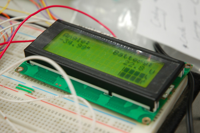
WEEK 10 SUMMARY
Accomplishments: LCD functions
completed including a string display and number display. The main
code module is complete. The LCD update module is nearly finished.
The custom battery symbol is complete.
Weekly Work Total: 14.0 hours
Project Work Total: 109.5 hours
Week 11
March 17, 2008 (6.5 hours):
Started
Homework 9. Completed the Introduction, half of Software Design
Considerations, and a third of Software Design Narrative. Also
worked on the software. Added some logic to display appropriate
level of the custom battery symbol depending on what the voltage
reading from the 24V batteries is. If the voltage is less than 4V
the battery shows completely empty, less than 10V and it is show
a quarter full, less than 16V and its half full, less than 22V its
three quarters full, and if its greater than or equal to 22V its
completely full. This completes the lcd_update function except for
small problem. Cleaned up the code.
March 18, 2008 (8.0 hours):
Continued
working on Homework 9. Completed the rest of the Software Design
Narrative. Also made flowcharts for every major function used in the
software. Then started on the TCSP PowerPoint needed for Wednesday.
The design considerations, function flowcharts, hierarchy block
diagram, and development status were all included and covered in the
presentation.
March 19, 2008 (6.0 hours):
Gave the
Software Design Narrative TCSP in class. Then went to lab after
class to finish Homework 9. The code modules were added online to
allow them to be viewed using the hot links in the homework. Finished
the last section of the homework which was the Software Design
Considerations. This took quite a bit more time since all of the
addresses for memory mapping, registers, and other data had to be
specified. Also the PCBs arrived. The rest of the group began to
populate the board. There have been some pin out problems with the
Linear Regulators as well as the accelerometer. The custom footprints
were made using the wrong pinout so the traces were cut and flywires
were added to correct the PCB. The accelerometer has been tested on
the board and is outputting the correct voltage but the LCD is not
displaying the correct value. This is most likely due to the fact that
the rest of the ATD pins that are floating since nothing else is wired.
Floating ATD pins have caused wrong readings so this will be fixed by
disconnecting the ATD from them in order to test the accelerometer.
WEEK 11 SUMMARY
Accomplishments: lcd_update, battery_alg,
and main function written, tested, and correct. Custom battery symbol
created. balance_alg function partially written. PCBs arrived. Finished
populating the PCBs. Homework 9 completed.
Weekly Work Total: 20.5 hours
Project Work Total: 130.0 hours
Week 12
March 24, 2008 (2.0 hours):
Met with
team in lab to decide on how to mount the vertical shaft for the Two
Wheel Deal. It is a 2" wide piece of steel. It was decided to mount it
using two horizontal holes to the front piece of steel stock frame.
The holes were measured in the frame as well as the shaft for Chuck.
Also it was decided that the shaft will stick past the bottom of the
frame 4". This is used to protect the front battery as well as the
motor controller board and microcontroller board. It protects those
components because when tipped forward far enough the vehicle stops
rotating and hits that. Then it was decided how the LCD box would be
mounted to the shaft. It was decided the box will also house the
joystick used for steering.
March 25, 2008 (3.0 hours):
Met with
team and took the metal shaft and frame to the tooling room to have it
drilled. Determined how to mount the batteries. It was decided that two
pieces of angled aluminum would be welded together in the shape of a "Z".
This way one side of the "Z" would fit under the battery holding it up
and the other side would be drilled through and a bolt would mount it to
the baseplate of the machine. A very basic drawing can be viewed below
that depicts what the holders look like. A weld is made along the
junction of the pieces. It is located at the dot on the side view.

March 26, 2008 (3.0 hours):
Met with
team to measure the pieces of metal Greg obtained from the scrap bin.
A picture was drawn showing how the pieces should be cut and welded
together. The pieces and the picture were then taken down to Chuck.
WEEK 12 SUMMARY
Accomplishments: Vertical shaft designed
and assembled. Box to house the LCD and joystick designed. Battery
mounts designed and being created.
Weekly Work Total: 8.0 hours
Project Work Total: 138.0 hours
Week 13
April 1, 2008 (7.0 hours):
Met with
Greg after class to obtain the metal for the battery holders from
Chuck H. Once these were obtained the rest of the team met and Chuck
B. let us work in a small machine shop to drill the holes needed. Two
holes were drilled in each of the four battery holders. Eight holes
were then drilled in the foot plate to connect the battery holders to
the plate. Four holes were then drilled in the footplate for each of
the motor controller PCBs. Then four holes were drilled in an aluminum
sheet that the microcontroller board is mounted to. Two holes were then
drilled in the aluminum sheet as well as one of the battery mounts to
attached the microcontroller board. Finally two holes were drilled in
the vertical shaft as well as the LCD box for mounting. The Two Wheel
Deal was then taken to the ECE477 lab where the batteries, PCBS, and
LCD box were attached. The batteries were then wired up and initial
testing using two wheels was started. The vehicle was blocked up so it
could be tested without moving all over the floor. Gain constants for
the proportional and derivative controller were adjusted until it
seemed adequate. The vehicle was then placed on the floor and the rest
angle adjusted so it would try to balance itself. After a few trials
and some constant adjusting the vehicle successfully balanced itself
althought it does drift slightly. Finally the rest angle was adjusted
again to allow a rider to attempt to balance on the vehicle. I was
the first to try it and the Two Wheel Deal worked well. A low quality
picture of the first ride is shown below:

The vehicle was very
sensitive to movements though. After the rest of the team tried it we
agreed the sensitivity needed to be lowered. I tried it again after
that and it worked perfect. The vehicle also worked perfectly going
forward and backward. One problem encountered was the aluminum hubs
are slipping. We plan to try and remake them out of steel which
should be stronger and less likely to slip.
April 2, 2008 (7.0 hours):
Met in lab
before the TCSP session. Began to look at how the joystick, which was
taken off a Microsoft XBox controller, would be mounted on the LCD
box. It was decided to use a small piece of development board to
mount the joystick on directly. Then after class Jeremy and I decided
to use 3/4" spacers to place between the development board and the
inside edge of the box. This allowed the correct amount of space to
remain between the joystick and the hole in the LCD box. This space
was necessary to allow the joystick to spring back to the original
position so the joystick wouldn't get stuck in the turn position. The
holes were then drilled for the joystick screws and the joystick was
attached. A picture can be viewed below.

Headers were soldered on the wires from the LCD and
joystick to allow a quick disconnect if necessary. Headers were then
soldered on both ends of a cable to connect to the microcontroller
board as well as the LCD and joystick. The cable was run and secured
to the vertical shaft. The program was changed to include the
steering algorithm. The vehicle was then tested and it was successful
after a few trials and changes. The gain needs to be increased still
to allow a quicker turn. I also arranged new hubs to be made out of
steel. The aluminum hubs we are using now are too soft and one has
been warped too much to work correctly. They should be finished and
attached by early next week. Pictures of the aluminum wheel hubs
being used now are shown below: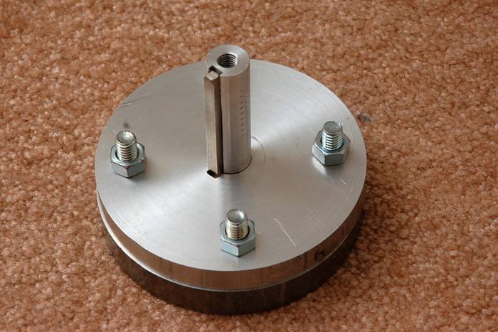
WEEK 13 SUMMARY
Accomplishments: Battery mounts made.
Electronics mounted underneath machine. LCD box milled. Two Wheel Deal
successfully balances and travels forward and backward with a rider.
Joystick attached. LCD box wired and connected. Two Wheel Deal
steering algorithm added and works correctly.
Weekly Work Total: 14.0 hours
Project Work Total: 152.0 hours
Week 14
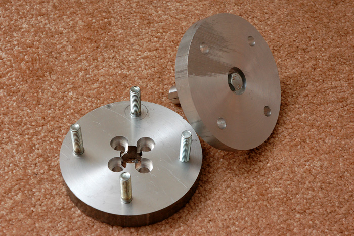
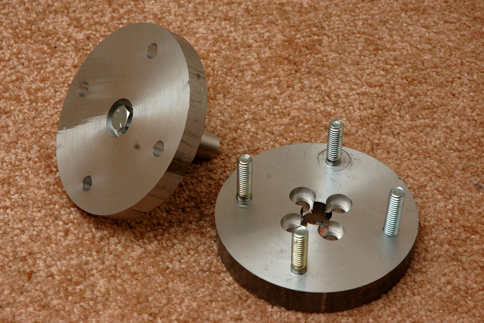
April 6, 2008 (4.0 hours):
Went home
to pick up the newly made hubs. They are now made out of steel to
prevent the slipping that was associated with the softer aluminum
metal. A very big thanks to Tom Hinton who made the new hubs with
some modifications made to some bolt holes and depths to help
strengthen the hubs and ease the assembly. Pictures of the new hubs
can be viewed below:


Also started Homework 12. Finished the Introduction and Ethics
portions of the homework.
April 7, 2008 (6.0 hours):
Continued
working on Homework 12. Finished the rest of the homework which
included the Environmental and Summary portions.
April 8, 2008 (11.0 hours):
Met in
lab with the newly machined steel hubs. Began to install them when
encountered the problem that the steel key was slightly too large to
allowed the desired loose fit clearance. The hub, shaft, key, and
wheel were taken to the machine shop to be pressed on using some
cocoa butter and an arbor press by Chuck H. The hub assembly was
then taken back upstairs and the shaft was pressed out about halfway
using a hammer and punch to allow the hub to be connected to the
frame. The wheel was then hammered the rest of the way back on. Then
the proportional and derivative constants were continually adjusted
to try and find solid performance from the vehicle. The first problem
encountered was it took a long time to change the constants because
the vehicle had to be reprogrammed everytime. Also the vehicle seemed
very sluggish to respond and it was determined that is because of the
filtering added to prevent the motors from reading every little
change in angle. Then the PowerPoint presentation was started and
completed for the Environmental TCSP session.
April 9, 2008 (5.0 hours):
Went to
lab to review and prepare for the Environmental TCSP presentation.
Gave the TCSP presentation. Then met in lab and first added two
potentiometers which could be adjusted to adjust the proportional and
derivative constants without having to continually reprogram it. The
total number of filter values was then reduced to prevent the
sluggish response found on April 8. Testing was then resumed to find
good constant values. This was first done by allowing the machine to
try and balance itself. The values that were finally decided on were
KP = 0.75 and KD = 1.20. Then each team member tried riding it to see
how it felt. Everyone thought it worked really well. It was driven
for about 30 minutes and the voltage on the batteries dropped about
1.5 V. Further testing will have to be done to determine about how
long the vehicle can be riden on fully charged batteries. The first
nonteam member, the lab advisor Chuck B., rode the vehicle also and
said it was very fun. A video of myself riding it can be viewed
below:
| Download Video |
The plan for the rest of the semester is to make the vehicle look nicer, create an easier charging system, and to add a power switch/dead man switch.
April 10, 2008 (4.0 hours):
Met with
team in lab to create the 5 PSSC videos. All team members rode the Two
Wheel Deal around in the basement of the EE building. The rides were
videotaped. The vehicle successfully drove up and down the steep
cement ramp in the EE basement. This helps with tests regarding the
vehicle operation in a variety of environments. The vehicle was also
taken up and down the inclines in EE170. These tests put a large load
on the motors but both the motor controller boards and the motors
stayed cool thanks to the fans and open body frame. One problem
encountered was the Two Wheel Deal would randomly reset causing the
motors to stop and the rider to have to step off the vehicle. This is
thought to be due to a loose wire connectly. Code was also added to
get an estimated to estimate the approximate speed of the vehicle.
April 11, 2008 (2.0 hours):
Met with
team in lab to test some new code changes on the Two Wheel Deal. The
loose wire was resoldered and code was added to allow the two steering
constants to be adjusted using external potentiometers. The KV
affects how sharply the rider can steer based on speed. The faster
the vehicle is moving the less sensitive the steering joystick is. KS
is the general gain constant for the overall steering. These constants
were adjusted and finally set on good values after various trials.
One last addition made was a deadband which prevents the vehicle from
drifting since the joystick doesn't always return to the exact same
position. A problem was also encountered when the "Program" button
was pressed in AVR Studio. A random signal was sent and the wheels
began to turn at full speed. This caused the programmer to get
slammed to the ground and crack. Chuck B. was able to replace this,
reflash it, and the problem was solved.
WEEK 14 SUMMARY
Accomplishments: New steel hubs made
and picked up. New steel hubs added. Successfully balances itself and
successfully riden. Homework 12 finished. Steering constants
determined. PSSC videos created. Variety of inclines navigated.
Weekly Work Total: 32.0 hours
Project Work Total: 184.0 hours
Week 15
April 15, 2008 (4.0 hours):
Met in
lab with team. Worked on the User Manual and finished it. Had to
add directions on how to drive the Two Wheel Deal as well as more
safety warnings and troubleshooting. The teams PSSC's were then
demonstrated to the GTA Karl Herb. The Two Wheel Deal officially
completed all the goals that were set at the beginning of the
semester.
April 16, 2008 (5.0 hours):
Met in
lab with team. Helped install and debug a new switch that changes
the rest angle for the vehicle. If the switch is forward that
indicates there is a rider on it and the rest angle is at -4
degrees which is more flat to allow easy riding for a passenger.
If the switch is backward that indicates the vehicle should
balance itself so a rest angle of -16 degrees is needed to keep
the weight of the LCD box set directly above the axle. The switch
works perfectly. The vehicle was then taken outside for the first
time. It worked really well and a top speed of about 10 mph was
estimated. A recurring problem occurred at top speed though
causing a wreck. The problem is that the microcontroller resets
randomly. When this happens the wheels stop spinning and cause the
rider to fall forward. It was thought that the linear regulator
was getting too hot and reseting. To prevent this an aluminum heat
sink was added. Insulation was also added to wires that are in the
LCD box to prevent any from shorting out and causing a voltage
drop to the microcontroller. The heat sink worked in dissipating
the heat and the insulation worked but the microcontroller is
still resetting. The problem is still being worked out. The
vehicle was also demonstrated to an EE382 class since the Two
Wheel Deal uses a PD controller.
WEEK 15 SUMMARY
Accomplishments: PSSCs demonstrated
to the GTA. Switch added to change between balancing itself and a
rider. Two Wheel Deal successfully taken outside. User Manual
completed.
Weekly Work Total: 9.0 hours
Project Work Total: 193.0 hours
Week 16
April 22, 2008 (2.0 hours):
Met
with team in lab to do some repairs on the Two Wheel Deal. Some
problems occurred over the week and weekend. First of all the hubs
had become loose and a wheel came off. To solve this the wheels
were removed using a gear puller. The hubs were then taken apart
and the bolts put back in using LockTight. This will help keep the
bolts tight under all the vibrations and hits the wheels may take.
Another problem was that in one hub the key stock shaved off when
the wheel came off so the key stock was taken out and repositioned
so the shaved off side was not in a crucial position. The hub was
then put back together using LockTight. Below is a picture of the
team removing the wheels: 
One final problem that was
fixed was to find a new balance angle without a rider. Probably
due to the many crashes that have happened, the vertical shaft has
bent slightly changing the center of gravity. This in effect means
the balance angle needed to be changed to ensure stability. The
new balance angle was found to be -17.5 degrees. Greg and Pete
also changed the steering algorithm to add some steering ability
at higher speeds because the previous algorithm prevented that.
April 23, 2008 (6.0 hours):
Met
in lab before class to work on the bonus presentation to be used
on Friday in the ECE270/ECE362 classes. Then presented the PSSCs
in class. Then after class started and completed the ECE Senior
Design Report due on Monday.
April 24, 2008 (3.0 hours):
Met
with team to finish the bonus presentations for Friday. Also
worked on the homeworks due Monday. Took some pictures for the
final report. The picture used in the final report can be viewed
below: 
April 25, 2008 (5.0 hours):
Met
with team in the ECE362 lecture. Participated in the bonus
presentation. Then worked and completed the first version of the
poster. Also finished the final report, printed it, and had it
bound. Then participated in the bonus presentation in the ECE270
lecture.
WEEK 16 SUMMARY
Accomplishments:
Wheel and Hub
problems fixed. New balance angle found. Steering algorithm
adjusted. Senior Design Report finished. Bonus Presentation
PowerPoint finished. Final Report finished and bound. First
version of poster finished. Completed Bonus Presentations.
Weekly Work Total: 16.0 hours
Project Work Total: 209.0 hours