Jared Suttles' Lab Notebook
Week 01
January 10, 2006 (1 hour):
This was the first day of class. We picked teams, and then we met to
discuss project ideas. We discussed many options, including projects based on the Illinois Tollway System's iPass, a
digital restaurant host/hostess aid, and a laser tag-like practice range. We finally decided on the digital restaurant
host/hostess. Our initial concern was that this was more of a software solution. It might be more appropriate to run
a software suite on a PDA for this application.
January 11, 2006 (1 hour):
This meeting was called to further discuss our current idea, the
digital host/hostess. We discussed different peripherals that we might be able to incorporate, including a barcode scanner
and/or magnetic card swipe reader. I decided to mention an idea that I came up with involving RFIDs and a retail
checkout lane. The point was to allow a whole shopping cart to go through a gate and be scanned quickly. We also
figured that we could charge a checking account or credit card and email a receipt to the customer. We decided it was
worthwhile to do further research into both of these ideas.
January 12, 2006 (2.5 hours):
Today, we wrote up the initial project idea proposal. We decided
to finally go with the RFID checkout system, and thus we spent a long time researching it. Writing the paper was
actually relatively difficult since we wanted to find accurate prices and we still didnt know much about RFID
technology. It was today that we realized that actually building an RFID out of ICs was going to be quite difficult, not
to mention expensive. We decided we'd like to use high-frequency RF, and we finally priced out a module and antenna.
The intial write up was completed after a long meeting. Check it out here.
WEEK 01 SUMMARY
Accomplishments: Founded the J Team. Decided upon the RFID project idea. Wrote up the initial
design proposal.
Weekly Work Total: 4.5 hours
Project Work Total: 4.5 hours
Week 02
January 16, 2006 (1.5 hours):
Today, I set up our 477 shay account today. I also figured out how
to map the email to Outlook Express and emailed my team with the instructions on how to do everything. (email us if you'd like).
January 18, 2006 (2 hours):
In class today, we learned that our project was too hard. I thought
that the anti-collision problem was going to be difficult, but I didnt know on what level. At this meeting, we discussed
two things. First, we talked about whether the problem really was too hard, and then how we could water it down to be
tractable. In this case, we read a couple of websites saying that RFID anti-collision technology is rather software
intensive and is very advanced (here is the document we read). This sounded hard, so
we thought of a one at a time checkout system instead. The second thing we discussed were different RFID based projects,
such as an RFID garage door.
January 19, 2006 (.25 hours):
We briefly discussed our new idea of a one at a time RFID checkout
system with Dr. Meyer. Glad to hear it sounded alright!
WEEK 02 SUMMARY
Accomplishments: Set up the shay account. Researched project alternatives and settled on the
new idea. Got new idea approved by Dr. Meyer.
Weekly Work Total: 3.75 hours
Project Work Total: 8.25 hours
Week 03
January 23, 2006 (2 hours):
Today, I spent a pretty long time on our webpage. I found a cool
template that we are using, and I built a framework for everything. It still has lorem ipsum stuff in it right now,
but it should be up and running at 100% by the end of the week.
January 24, 2006 (2 hours):
I finished setting up the website today, and added some things to it.
It now has a sample photo album, which I will replace with relavent pictures when I get some. It also has some documents
posted now.
January 24, 2006 (1 hour):
This meeting was mainly used to make the Project
Specific Success Criteria. Jonathan could not make it due to a meeting with his research team. We came up with a lot of
good, measurable ideas, and it turned out very well.
January 26, 2006 (2 hours):
I finally updated this page for the first time. I will be sure to keep up
with it as the semester goes since I now realize how hard it is to remember things after-the-fact.
January 26, 2006 (3 hours):
I researched specific design components with Jennifer, and found suitable
options for all of our necessary peripherals, as well as the processor. The
neCore12 MC9S12NE64 10/100 Ethernet module fit
our needs nicely, and is relatively inexpensive. We also developed a block diagram for the project, and finished the proposal.
WEEK 03 SUMMARY
Accomplishments: Finished the framework for the team webpage. Decided upon our PSSC.
Weekly Work Total: 10 hours
Project Work Total: 18.25 hours
Week 04
February 1, 2006 (1.5 hours):
We met today to discuss the cost of our prototype and samples. We decided
on many things, including who would contact which companies, and what we would try to get for free or not. We also decided
to investigate the possibility of just using the 9S12NE64 chip, rather than buying the Technological Arts module. Josh and
Jonathan are going to do most of the procurement work, but we will all be involved after we understand things better.
February 2, 2006 (1.5 hours):
We have discussed the results of our investigations, and we have found
that it is probably not very difficult to build our own NE64 module using components, and it would be much more cost effective.
Hence, we have ordered a few sample chips, and even think we have been able to get a DEMO board for the NE64, which is pretty
awesome considering its cost. TI on the other hand, gave us some bad news, saying that not only can they give us any free
samples of the RFID readers, but we also need to plan on buying/building an antenna for this reader. The cheapest antenna
that TI sells is almost $200 and I'm not sure it even interfaces with the reader we are looking at. We will be moving forward
with our procurement, and will also be checking new vendors.
WEEK 04 SUMMARY
Accomplishments: Decided on many components and have ordered many samples. Hit a road block with the
RFID reader, but hopefully we can figure it out next week.
Weekly Work Total: 3 hours
Project Work Total: 21.25 hours
Week 05
February 6, 2006 (1.5 hours):
I researched parts on my own today. I was hoping to remove some questions
about what parts we would be using in our design before our meeting. This was because we had about 3-4 choices chosen for each
part. I was successful in ruling out a few parts, and applying for a few samples, but we'll see how that goes...
February 7, 2006 (3 hours):
This was probably our largest and most important team meating to date. We had
to decide on many parts that we were going to use in the papers. We succeeded in settling the debates on many parts, but most
importantly, we chose all of the major components. You can find all of the data sheets for our chosen parts on
our webpage. We also began to think about writing the 2 homeworks. We brainstormed ideas, and discussed ideas that we had all
prepared prior to the meeting. We also made the important decision that we were going to try and make this a consumer friendly (and
thus visually appealing) product. Though we dont want to get anyone's hopes up...
February 7, 2006 (2 hours):
Jen and I stayed up late tonight to work on the TCSP presentation
and the PCB footprint layout. Learning OrCAD layout from scratch wasnt much fun, and it took me
quite some time to be able to place anything at all on the screen. I then had to work to find which footprints were right for our
chips. This meant I had to get intimate with our data sheets. It was a long night, but I was very happy with
the results.
February 8, 2006 (0.5 hours):
Jen and I went to office hours today to ask Nick a couple of questions about
using Layout, and also about component selection. We also briefly ran ideas through him about how to use OpenTCP, since we have
no prior experience with it.
February 8, 2006 (3 hours):
This was a long, tedious meeting where we revised and edited
Josh's paper (HW4). It was a little difficult to have a totally productive meeting, since I was also on RA duty at the same
time, and I often had to attend to sudden issues. All in all we got a lot done, including finishing Josh's paper (except the CAD
drawing, which will be done tomorrow).
February 9, 2006 (1 hours):
I spent some time in the middle of the day today ordering samples of the MAX233A
RS232 transceiver and also finally finding an in-stock Pulse Engineering RJ45 w/integrated magnetics jack. I was SO excited, since
every other brand I have found has been entirely out of stock.
February 9, 2006 (3 hours):
This was another long and hard meeting, where we edited
Jonathan's paper (HW3). His paper was quite a bit longer than Josh's by nature, and also required a lot more technical data.
Although it took a long time, it turned out well, and one of the (seemingly) most important papers is now done. In class today,
we also discussed some revised PSSCs with Dr. Meyer, per his suggestions on the proposal comments. We have decided perhaps to
interface with a receipt printer as well as email the receipt, but we were unable to incorporate that information into the papers
due tomorrow.
February 9, 2006 (1 hours):
I spent a short while tonight updating and beautifying our
webpage. Check out the new, more organized documents page. Or, checkout the new, improved bios on the
about page.
WEEK 05 SUMMARY
Accomplishments: Finalized many component selections, requested many samples. Finished HW3 and HW4 papers.
Learned a little about OrCAD Layout. Updated webpage. Discussed and adopted (pending)
some new PSSCs.
Weekly Work Total: 15 hours
Project Work Total: 36.25 hours
Week 06
February 17, 2006 (4 hours):
Today Jonathan and Josh went to office hours to try and figure out our
power supply. I also spent a long time researching power supply components, and found a few parts (Fairchild
FAN1086 LDO Voltage Regulators) that would fit the application. Since I am writing this in retrospect, I can say that we
thought we only had to get a 3.3 and 5V signal. We also began working on the schematic today, implementing the circuits
that were provided in the data sheets for oscillators and ethernet.
February 19, 2006 (2 hours):
This is when I realized that we needed a 9 or 12V signal to power the RFID
reader. This presented a few problems, since in order to use the same type of LDO regulator, we would need an 11+ V source,
which exceeds the absolute maximum rating for the 3.3 and 5V LDO regulators. Hence, I researched and found a new type of LDO
regulator from TI called a LM317 that was adjustable, and hence accepted voltages from 0-40V. By selecting the correct resistor
network, it would output the correct voltage. The problem with this solution is that this results in a 5+ Watt drop across the
3.3V regulator when we use a 15V source... That would make things pretty hot without a really good heat sink.
WEEK 06 SUMMARY
Accomplishments: Spent a lot of time on the power supply design, and also got a good running start on
the schematic.
Weekly Work Total: 6 hours
Project Work Total: 42.25 hours
Week 07
February 20, 2006 (4 hours):
Again, I spent the majority of the day researching alternatives for the
power supply. I am having trouble finding switching systems that can provide the required amperage to run the signals we need.
We are going to need 1 A for the 5V signal, .5 A for the 3.3V, and .1 A for the 12V. After many wasted hours, I spent some time
helping Jen out by working on the schematic, and also made my first run through ECO, which included making a couple of custom
footprints. This was a trip, as I had to make an RJ45 jack with an extra 4 pins for LEDs and also2 extra holes for mounting.
February 21, 2006 (10 hours):
This was my longest day so far... I had to redo the power supply AGAIN, as
we finally spoke with Dr. Meyer and decided that a step-up converter would be the best way ot provide the 12V signal. So I
researched again, and found a TI converter that matched our specs, and I ordered some samples. I also spent a long time working
on the PCB, which was a tedious job since I really didnt know anything about how to use Layout. I finally began to understand
the tutorials, and I began to route signals. The routing wasnt going very well, but I experimented long into the night and I
feel like I have at least a cursory grasp on things. We also spent a long time working on our TCSP presentation, which we are
prepared to present tomorrow should our ticket be drawn.
February 22, 2006 (7 hours):
Again, I spent almost my entire waking day in the lab working on the PCB and
finalizing part selection. I began doing small iterations of the PCB, making small changes at a time. I am really becoming
comfortable with Layout, which is amazing to me, since I had no idea only 2 days ago. Jonathan and Jen worked a lot on the paper
that went along with the schematic. Josh also wired up the evaluation board that Chuck loaned to us for the first time. He
installed the software on my laptop, and we are going to be using that from now on to develop code. Tonight, I taught Jonathan
how to use the Layout software, and he began wiring up the last parts of the PCB.
February 23, 2006 (6 hours):
I am amazed today... Jonathan stayed up all night and finished wiring the
whole PCB. He went totally above and beyond what I would have expected. While I did spend a couple of hours fixing minor
mistakes and making small changes, this was an awesome help. I also spent the time today writing my paper, which I was
concerned was not going to be long enough. It turned out that there were more than enough topics to discuss to make a good
paper. I unfortunately noticed a couple of PCB considerations which I probably should have taken into account earlier. At
this point, it is impossible to make the changes for this paper, but I am making notes for next week.
February 24, 2006 (1 hours):After the longest week of my life, I spent the
morning incorporating changes emailed to me by my teammates, and then turning my paper in. We also had to submit a change form
for our PSSC's so that we can have them updated by our Design Review on Tuesday.
WEEK 07 SUMMARY
Accomplishments: Spent the longest week of my life creating the PCB and writing my paper...
Weekly Work Total: 28 hours
Project Work Total: 70.25 hours
Week 08
February 26, 2006 (4 hours):
Today we all met and worked on the Design Review presentation. We made
updates to the
schematic and PCB, and we created all of the slides. We also delegated speaking roles, and we are well prepared for the design
review. Some work will need to be done tomorrow, but not much. Josh wasnt available all day, so we need to finish his part
tomorrow.
February 27, 2006 (2 hours):
We made some small changes to the presentation, which included taking
updated screenshots of the PCB and schematic. We also took time today to print the 11x17 plots of the schematics. Finally,
tonight we printed a bunch of PCB handouts... This was tough since the 1:1 printing wasnt working when using Adobe PDF as the
printer. So I had to photoshop and scale it. I will try to figure this out later.
February 28, 2006 (4 hours):
After getting THOROUGHLY grilled by the panel at todays Design Review, we
spent some significant time reviewing the schematic and PCB and attempting to implement most of the changes that the panel
suggested. The major one we wanted to tackle was to purchase all of our parts so that we can make meaningful changes to the
PCB. I ordered pretty much all of our parts from DigiKey, and we hope to receive them before the end of the week. This has
lifted a great weight off of our shoulders, and I think I'm going to take a few days off to study for some other classes.
February 28, 2006 (1 hours):
I spent an hour checking all of our data sheets to make sure that the
voltage swings on logic pins for our peripherals was large enough to accept the 3.3V output from our microcontroller. This had
been a concern during the Design Review. I was pleased to find that all of our parts were 3.3V tolerant. Thus, we dont need
to buy and level translators.
March 2, 2006 (2 hours):
I found today that I was actually wrong about the input tolerance of all of our
peripherals. I hadn't thought that the RS-232 level translator wouldnt be correct, but it in fact worked only with 5V inputs.
I spent a short while surfing Maxim's website and I found the MAX3233E Level Translator that uses internal capacitors, and is made for 3.3V inputs. I am very happy
that this didnt take long to find, and that it is the same footprint and basic part as the previous. It does have a slightly
different pinout, so I spent some time redoing the schematic to reflect this change.
March 4, 2006 (5 hours):
Josh works Sunday nights, so he couldnt attend, but Jonathan, Jennifer and I
spent a long time in lab working on a lot of things. I focused most of my time on generating custom footprints for the PCB
layout of our specific discrete components. This took some time, since we hadn't even thought of what passive components we
would be using during our previous iterations. I also helped Jonathan load some startup code onto the evaluation board for
the first time. Josh had worked on it before, but we had never tried, so it took a little while to figure out. At first,
Code Warrior was saying that we were missing a NE64.pe file. We found that file by running a NE64 patch. We then realized
that we wouldnt actually need to implement the Processor Expert tool, so that .pe file wasnt necessary. I learned a lot tonight
and set up a good framework for further work on the PCB.
WEEK 08 SUMMARY
Accomplishments: Prepared and presented the Design Review. Got ripped apart during the review, so
took a lot of the advice and implemented the suggestions. Bought all of our parts, and
made sure that they all worked. Began the process of completely redoing the PCB and
schematic.
Weekly Work Total: 18 hours
Project Work Total: 88.25 hours
Week 09
March 7, 2006 (2.5 hours):
I went to office hours today with Jen. I wanted to ask Brian about some final
concerns involving part selection and interfacing. First, there was a 1500 pF capacitor in the circuit for the switching
regulator, and I accidently thought that was 1.5 uF, when it was infact a 1.5 nF capacitor. He told us we could use a non polar
capacitor, which was great news, since I could find that in the cabinet. I was also concerned about how the printer we received
had a male DB9 port on the back, and I had anticipated a female. Brian said that I can just buy a gender changer for our purposes.
We also got Brian to do our part layout and he said that everything was good, which was awesome news. All that is left is
to re-route the whole PCB.
March 7, 2006 (5 hours):
I just had a small break for 495f lecture, but Jonathan and I spent the rest of
the evening working on the PCB layout. Specifically, I routed all of the ethernet circuit, which was a major concern during the
design review. It was somewhat challenging since there was a lot of hardware to pack into a 1 inch area. It took some time, but
but I finished routing that section, and moved on the the rest of the micro pins. Jonathan took over at this point and managed to
finish the entire board by the next morning. Meanwhile, I worked on the circuits for the power supply. This was the first time
that I had actually wired up a prototype circuit and checked the output voltage. Luckily, the outputs were perfect. I actually
cant prototype the 12 V switching regulator circuit since I dont have any through-hole inductors. It is probably OK though, since
the RFID reader can run on a wide range of voltages, and the most important thing is that the signal is clean and regulated, which
will hopefuly be the case. When I left the lab, Jennifer and I made a few small changes to the schematic in order to update the pin
orientation of the LCD header and make a couple more small changes. The final version of the schematic
can be found on the documents page.
March 8, 2006 (3.5 hours):
Since Jonathan did a great job routing the entire board last night, I spent most
of the morning taking small time chunks to change things. I made the vias a little smaller and then changed some routes to be more
optimally routed and spaced. I also fixed a couple of small things mentioned during the Progress Briefing today.
March 9, 2006 (2.5 hours):
I spent some time updating more small changes to make the design more optimal
today. Later, Jen and I redlined the entire PCB and schematic and corrected a couple of traces that should have
been routed more directly, rather than through multiple components. After making sure the whole PCB was correct, I ran the post
processing, and submitted the files it generated to the freedfm website. It mentioned quite a few errors that it could automatically
fix, but no "show stoppers", which is good news. So I zipped everything up and emailed it to Barry. It felt GREAT to be done with
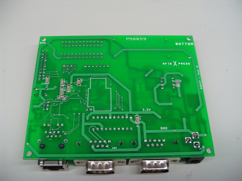
this a day early. The final top and bottom coppers
can be found on the documents page.
WEEK 09 SUMMARY
Accomplishments: We finalized all of the parts and footprints for our design. We also placed and routed the
entire board from scratch again. When it was all said and done, we verified our layout, and we
submitted it to the website and it came back good. A huge part of this project is now complete!
Weekly Work Total: 13.5 hours
Project Work Total: 101.75 hours
Week 10
March 19, 2006 (6 hours):
Because I was on RA duty this weekend, I decided to spend the time working on
the project, and Jen and Jonathan were also here, so we met in lab to work on software. Josh had gotten a BDM from Chuck that
works for our micro (the first one was 5V only). So we began writing code and loading it onto the chip to test functions. The
serial code is going to be the hardest at this point, because we want to keep the serial monitor code loaded on the chip in case
the BDM fails. However, we decided to work on the Keypad code. I thought it would be a good idea to hook up a 7 segment LED and
test the DEMO kit we received from Freescale. We are using Port G to drive the leds, and we are using Port S to control the keypad
polling. The code basically uses a modulo counter to iterate through the 4 output signals we use to choose columns, and then we
check the row signals to see if one is high. It isnt working well right now, as no matter what we try, the Port S[0] pin is
driving a 3.3V high, though it should be an input... I plan on attending office hours later to get this working.
WEEK 10 SUMMARY
Accomplishments: Worked on software, mainly the keypad algorithm. We are still having problems, but I think
we actually did decent work for one night (especially since its Spring Break still).
Weekly Work Total: 6 hours
Project Work Total: 107.75 hours
Week 11
March 21, 2006 (1.25 hours):
After lectures today, Jonathan, Jen, and I went to lab to work on the keypad
software again. Jonathan had to leave shortly thereafter for a research group meeting, but Jen and I kept working on the code.
We decided that for some reason the Port S[0] pin just wont work. We then moved the row reading pins to Port J, and things finally
started to work correctly. We first got the 7-segment LED to output a different hex character for each of the 16 keys. We then
thought it would be a good idea to test out the internal pull devices of the chip. We found it was really easy, and we could
remove our external pull down resistors. Jen and I considered stopping here, but our sudden success made us want to test more, so
we added code to receive and check a PIN against a hardcoded "correct" pin value. We anticipated that the code would be working
much too fast to allow for 4 key presses without software support (one press would be read as a lot, due to the clockrate). When
we confirmed this fear, we added a simple loop that holds the code until the button is released. This worked well, and we succeeded
in accepting and checking the PIN. We still dont know why Port S[0] wouldnt act as an input, but it will be used for serial
communication anyway, so that shouldnt be a problem.
Keypad + PIN Check Code Listing
March 22, 2006 (3 hours):
The software is really starting to come along. Jonathan, Jen and I went to lab
and began working on new modules today. I thought it best to start working on the evaluation board since it had some 2 free
serial ports, and serial communication was our first goal. We first hooked up the RFID reader to one of the serial ports, and
we started writing serial initialization code. We ran into our first problem when we had to figure out what Baud divisor to use
to get the 9600 baud we needed. We needed to know our internal Bus Clock, and we found a seemingly contradictive statement in
the datasheet. It stated that the Bus Clock was half of the Core Clock, and the external crystal we are using is 25 MHz. Hence,
we assumed (without reading very much) that the Core Clock was 25 MHz and hence that the Bus Clock was 12.5 MHz. The baud
divisor we first tried didnt work, so we then remembered that in order to have the ethernet run at full speed, the Bus Clock had
to be 25 MHz, so we tried a new Baud divisor and it worked perfectly. We knew that it was working, because we used the other
serial port to send the just-read data to the computer and we viewed it on hyperterminal. We knew that there might be a race
condition where the RFID reader would broadcast the RFID serial number multiple times, and we confimed that it was in fact the
case. This can be easily handled later on by keeping track of serial numbers that have been previously scanned.
We then
began working with the printer, and quickly succeeded in getting it configured to be used with Serial communication, 9600 baud,
no flow control, and the US character set. We then attached it and found that the serial printing standard is awesome, and it
simply accepts the ASCII value for most characters and it prints them. We easily made a simple printing program, and we then
coupled it the RFID reading, and output the tag ID read and some text. We found that it at times wrote a random character
before the RFID value. We think its a product of transferring the data directly from one serial port's read to the other
serial port to be written, which wont happen in our final product, so we dont anticipate this being a problem.
We are
excited that things are going so well in software, but Josh is still trying to figure out the ethernet code. Hopefully that
goes as smoothly as the rest of our code.
RS232 Communication Test Code Listing
RFID + Printer Test Code Listing
March 23, 2006 (3 hours):
I came over to Jonathan's room tonight to help out with the LCD code. I ended
up taking a long time to convert the monochrome bitmap we had into a binary array that we could use in our project. I first
had to download a program called Batch Converter (though I'm sure other programs
would work as well) that converted the BMP file to a PBM (portable bit map) format. This PBM format is basically a very small
header, followed by the byte by byte values of the bitmap. This worked brilliantly for what we needed. I then just needed
to get the actual binary out of the file, which wasnt very easy since notepad encodes it to ascii. However, I found a
website that provided a solution:
perl
-wne'printf "%08b ", ord $_ for split //' foobar.bmp (I added a "> logo.bin" to the end to capture it in a file.)
After that, I imported it into excel to line up the bytes in a nice order and do some string manipulations. I then copied it
all into word to format it right, and I finally had an array. That took a while, but it was worth it. Here is the binary
before being manipulated: binary file. And here it is in ASM format: asm text file.
March 24, 2006 (4 hours):
Today, I worked on 2 parts of the project. Josh and I worked on the ethernet
code for a while, and Jennifer worked on ohming out the board and checking it under a microscope for mistakes. It turned out
that the board looks fine, but our ethernet code was not going so well. A major problem was that we couldnt use the BDM to
program any of the ethernet sample code onto our evaluation board. We had to use the serial monitor, which isnt an option
in the future since we need both serial ports for our project. When we couldnt really get anything to work, we decided to
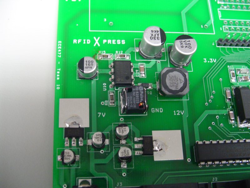
shift our focus the power supply. Josh went to research ethernet in his room, and Jen and I because to work on the board.
We soldered on the two voltage regulators without much issue. I did solder a polarized capacitor on backwards, but with the
solder wick, I was able to easily remove it and resolder it correctly. We checked these two power signals and they were both
accurate and clean. We then worked on the switching supply, where we had a couple of problems. First, we soldered a resistor
in the wrong spot. Second we realized that we had alotted a small capacitor footprint for a 100uF capacitor, which was much
larger. We found a slightly smaller capacitor, and we soldered it on as best we could. It made a good connection and it seems
to work just fine. We were unsure as to the actual value of this voltage, since we were unable to test it with the surface mount
inductors that we had bought, but it turned out that we had a perfect 12.00 volt signal. It was also very clean. We left the
power supply running over night so as to "burn" it in.
March 25, 2006 (2 hours):
Today, Jen decided to solder on all of the bypass capacitors. I thought it
would be a good idea to ask around about the BDM problems we were having, and James Doty showed me how to use it without any
of the settings I was trying to configure. This is huge, because we have struggled for a long time on how to get it working.
Josh also came to lab, saying that he had gotten the BDM to work, which was funny since I had also just figured it out.
So we began to work on the ethernet code again, and we had a huge breakthrough. We found that we could spoof the MAC address
and all of the other ethernet settings on our board to mirror our provided ECN computer. When we did so, and we plugged the
CAT5 cable from the computer into the board, we could ping the board via a PAL internet connection. This meant that the board
was accepting and sending TCP/IP packets over the internet. Basically, we need only find out how to send specific packets now
to make it so that we can access our external database and send emails.
March 25, 2006 (2.5 hours):
I went to Jonathan's room again tonight to work on the LCD code. He had a
test circuit up and running. He was trying to figure out how to get his old assembly code from 362 to run on the demo kit.
After struggling with it for a while, we decided to just convert it to C code. We used his assembly as the base, and we
wrote C to do the same thing. We never got it to work before calling it a night, and we realized right before we did that
it was because we didnt attach the LCD logic Vss and Vdd signals. That would make it hard to turn on... We plan on working
on that tomorrow again.
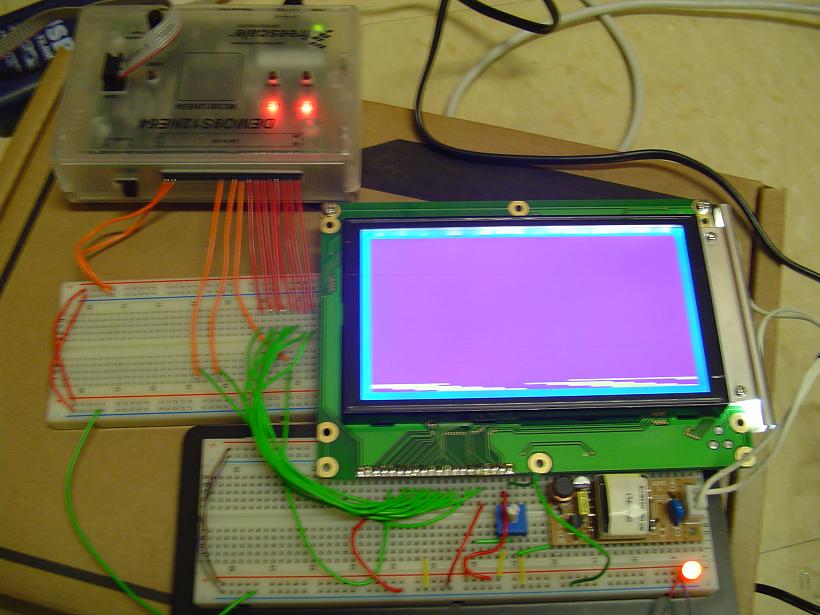
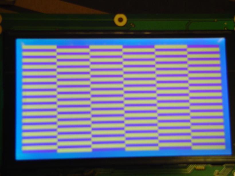
March 26, 2006 (5 hours):
The LCD was the main focus of the night. Jonathan and Jennifer came to my
dorm room because I was on RA duty, and we worked there. Last night, we had decided it would be a better idea to just use
C code, since neither of us really understood the Assembly all that well. We might try and go back to assembly just for
efficiency sake, but we'll decide that later. We worked for a long time, and we realized that we were having trouble because
the 5V supply that provided the backlight and the logic supply had a different ground from the 3.3V signal coming from the
demo kit. We didnt know if it was a great idea, but we tied the two together and everything started working! We made a few
test screens, and we ran into an error about allocating memory... It might be because of the size of the bitmap we are using
for the logo is too big, but then its only 7k, so that shouldnt be a problem. Anyway, we chopped off the last few lines,
and it worked. So we decided to minimize the drawing by taking all of the whitespace off the top and bottom and hard coding
it into the code. This saved us about 2-3k of memory. Now, everything in our project has at least some code that works,
and that is awesome.
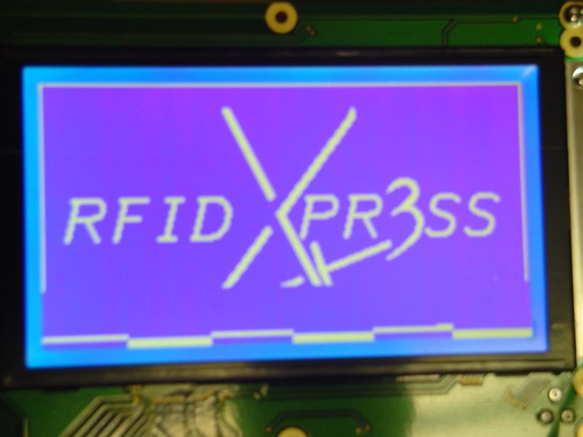
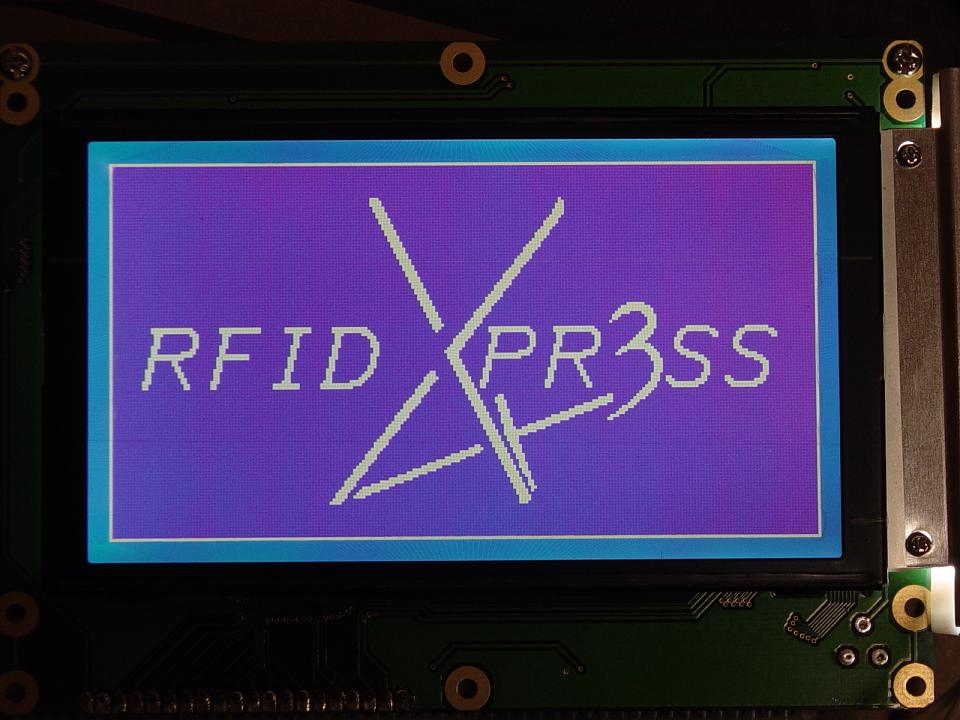 <- wicked cool logo, props to
Jonathan with his MS Paint Skills
<- wicked cool logo, props to
Jonathan with his MS Paint Skills
LCD Logo Display Test Code Listing
WEEK 11 SUMMARY
Accomplishments: Coded RFID / Printer Serial Test Code. Ability to ping the eval board over general
internet connection. BDM now works to flash any code. Coded keypad polling test code. Created logo binary
file. Coded working LCD initialization and Logo Display code.
Weekly Work Total: 22.75 hours
Project Work Total: 130.25 hours
Week 12
March 27, 2006 (4 hours):
Today, I spent probably too much time on the cool
RFID xpr3ss Code Viewer webpage... Afterwards I determined that shay really should have PHP
installed on it, as using javascript as a hack to do what I needed is really kind of shady. I also found a really strange bug
where if we put a index.something file in the Codes directory, it will break the autoloading link list on the right side of
the page. This is because of the hack way I did it in javascript, so we just will make sure to not use a code file named index.
As far as progressing the project, I did assist Jonathan in further testing the LCD. He had simplified our code to
use repeatable functions, but the test code has ceased to work. I looked over the code, and we quickly got it working. His
reset logic was inverted, so the LCD was in constant reset mode. He got the Character mode working tonight, so everything is
going very well.
LCD Test Code v2
March 28, 2006 (2 hours):
After lecture today, we went to lab and worked on a lot of things. I went
ahead and soldered our microcontroller onto our pcb, Jennifer developed a code heirarchical diagram and pseudocode for our
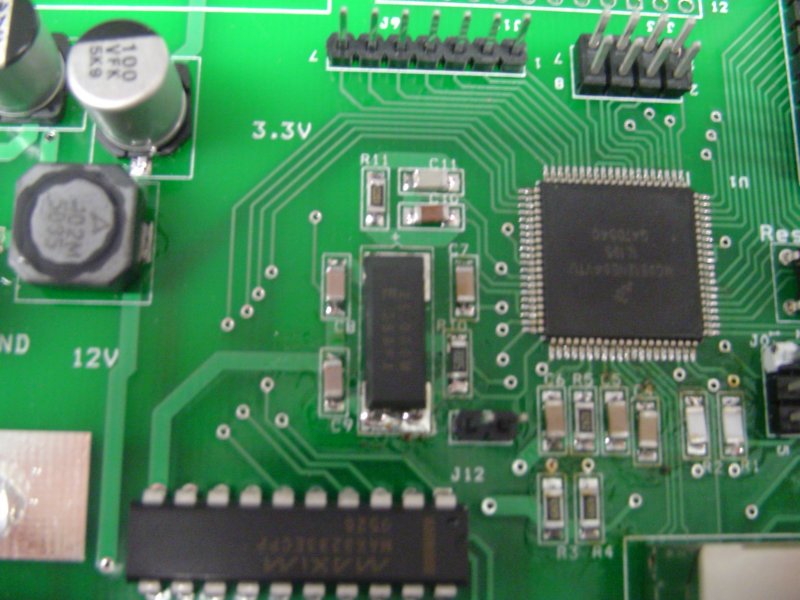
design, Josh continued to work on ethernet code, and Jonathan continued to update his software flowchart to match our
design. Soldering the microcontroller was stressful, since I wanted to make it perfect, and there were inherently some pins
that did not want to solder nicely. I ended up finishing the job under the microscope, which was actually a really cool
experience. It was neat to watch the solder heat up and then flow with the flux, and it was easy to know when to stop heating
the pins. We all had to leave for other classes, but we accomplished a lot in this short period.
March 28, 2006 (3 hours):
We worked on the Software Narrative TCSP tonight. We basically had to decide
on a lot of different aspects of the design from a software perspective. We discussed many options of program flow and
implementation before settling on a hybrid system we are calling Interrupt Flag Driven, Polling State Machine. It is based upon
a main polling loop which first checks the state of the system, and then checks certain flags depending upon which state
we are in, and then handles the flags as needed. This gives the most control to the main loop, which adds flexibility and
ease of development to the program flow. You can read more about it, as well as the actual TCSP we came up with by visiting
docs page or the direct link below.
Software Narrative TCSP
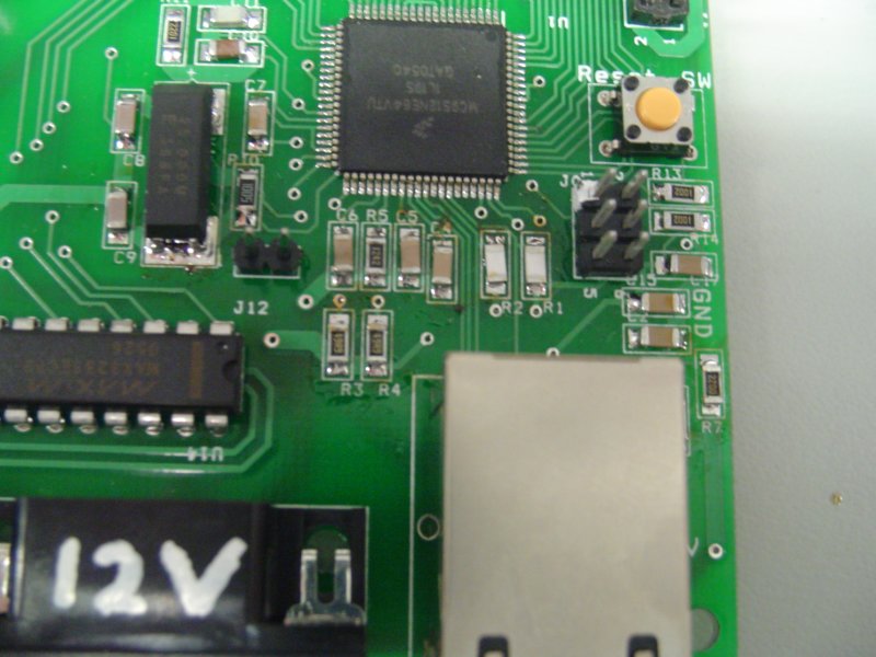
March 29, 2006 (2 hours):
I spent a couple of hours in the lab today populating more of our board. I
added the Reset circuit and began the oscillator circuit. With these on, the board is actually near completion, which is
exciting.
March 30, 2006 (4 hours):
Tonight, Jennifer and I helped Jonathan and Josh with revisions to their papers.
Though we have waited a long time to finish these assignments, the night went well. I helped Jonathan the most with his paper
(Software Narrative) and Jennifer helped with both papers. Inherently the Software paper was slightly more complicated, and thus
it required quite a bit of discussion and revision. Both papers can be found on our docs page or in the
direct links below.
Software Design Considerations
Patent Liability Analysis
WEEK 12 SUMMARY
Accomplishments: Added the microcontroller, reset, and most of the oscilattor circuit to the PCB.
Developed the Code Viewier webpage. Finished the
Software TCSP, Software Narrative, and Patent Liability Analysis.
Weekly Work Total: 15 hours
Project Work Total: 145.25 hours
Week 13
April 4, 2006 (5.5 hours):
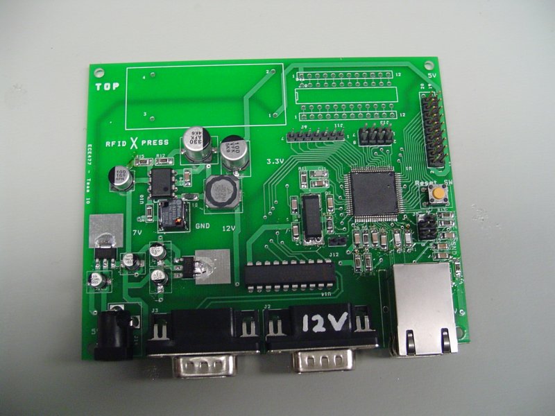
Today was a very exciting day! We made a lot of progress populating the PCB
and we were also able to load some successful code onto the board. Jennifer populated the oscillator, RS232, and EPHY circuits,
and I worked on a couple of pieces of code to test the boards functionality. I wrote a heartbeat function that simply flashed an
LED on and off. Once the board was populated enough to try it out, we loaded it up and it worked beautifully. This was a great
thing to see since we were all nervous about the board. I then ported over the RS232 code from the code written for the demo kits
to code that would work on our board. We tested it out, and it worked again! So I added some code that would do some simple
manipulation and would look up a name and price based on the serial number. It took some debugging, but it worked! We dont have
any code to test the ethernet code, but we are anxious to test that out too.
April 5, 2006 (4 hours):
Our progress briefing in lab today was excellent. We could actually say that we
had a lot of things working on the actual board and that we anticipated having the project completed ahead of schedule. We mentioned
that our voltage regulator was running a little hot, and Chuck offered us a piece of copper to dissipate the heat.
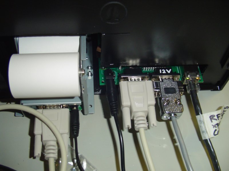
We also
had one of the worse experiences of the project so far today... Jennifer and I realized that we had made a major error in the design
of the ethernet circuitry. Basically, an RJ45 connection
has 4 lines that are of major concern: TxP, TxN, RxP, and RxN. We had swapped the Tx and Rx pairs, and had also swapped the N and P
in each pair. This was mostly due to an inconsistency between the datasheet for our
RJ45 jack and the suggested ethernet schematic for our microcontroller. We
literally had the soldering iron hot and the solderwick in hand before I thought of a better idea. We could just make a custom
CAT5 cable that would work for our application. After searching long and far for a kit to make a cable, we found a friend of
Josh's that made us a cable. Unforunately, one of the connections was bad on that attempt, so we had to find Chuck, who gave us
a kit to add a new end to the cable. This time it worked perfectly. The Startup Demo code allowed our board to establish a link
with the desktop computer and we were able to ping the board's IP address. This means that every major peripheral works on our
board!
April 6, 2006 (3 hours):
Jennifer and I spent a long time tonight working on the main state machine code
for the project. We started with the pseudocode that Jen wrote before we had done much decision making, so many changes were
needed, but it did provide an excellent framework for the eventual final product. Although much is left to be done, this is most
definitely going to be a work in progress for the remainder of development. A copy of our various versions of main code
can be found on the codeviewer page.
April 7, 2006 (1.5 hours):
Jennifer and I again worked on the main code today. We finished the state machine
and began attempting to integrate the code modules that we had finished in previous testing. We identified many of the different
modules that have yet to be written and need to be. We made some changes to our original ideas, such as storing the PIN as an
array of characters rather than an integer. This is best, as it adds ease of use to the code, as well as ease of computation.
The latest version of our code is here.
April 8, 2006 (2 hours):
I went into lab today with Jen and I designed a large test circuit meant to utilize
all of the different peripherals at once. I hooked up the keypad, RFID reader, printer, and the EVB board all in one large circuit.
I never got around to trying it out, but I am sure I will do that tomorrow, as we intend to get to lab early. Jennifer designed
just about all of our message screens for the LCD based upon the various states. We had determined that it was easiest to have no
real arguments to the UpdateLCD method, and rather to just have it switch off of the state variable and determine what to display
based upon that. I began to compile the main code before we left, but there are still many errors to be ironed out.
April 9, 2006 (6 hours):
The whole team got up bright and early and went to lab today. We worked on a lot
of things and got a lot done. My first task was to get the RFID interrupt code working. I ran into my first problem when the
EVB board wouldnt even acknowledge that an RFID had been scanned... I hooked the reader up to our real board, and the code worked
nicely, although interrupts still dont work... I developed a non-interrupt solution that should work since our code is running so
fast, but it would be nice to have that functionality as well.
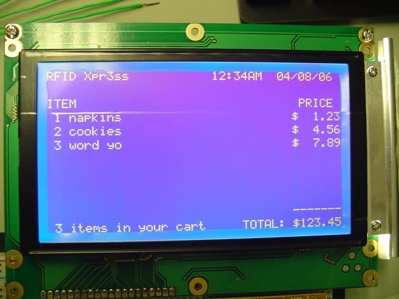
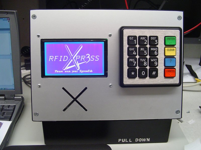
The other things we did today were integrate Jonathans LCD
code into the main function, as well as Jen's printer code. Jonathan's code had a few bugs to work out, as we realized that we
needed to write a simple string copy method, which we made quickly, and things fell right into place. See below for and image of
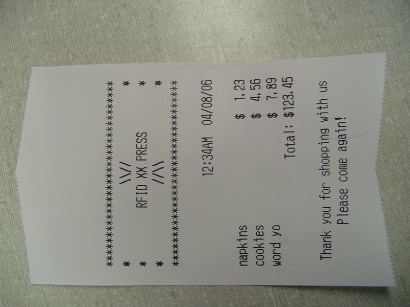
the shopping cart user interface. The printer code also didnt want to work at first. We wanted to run the code on our board, but
currently our board uses the printer's power supply, so we tried to use the triple output power supply to do the trick, but it had
a bad connection. We used the DEMO kit, and it now works awesomely. A picture of the receipt format can also be found below. The
test code, with the LCD and Printer methods in it can be found here.
WEEK 13 SUMMARY
Accomplishments: Completely populated the board. Worked extensively on the main function code. Saved the
ethernet circuit from certain doom by creating a custom CAT5 cable. Created fully functional versions
of the RFID handler, LCD update, and Receipt Printer codes.
Weekly Work Total: 22 hours
Project Work Total: 167.25 hours
Week 14
April 10, 2006 (2 hours):
Today was meant to help us figure out the problem with the interrupts... We have
tried many things. We have put a simple piece of code into the dummy ISR that the entire vector table points to, and the code
never reaches that code. Anyway, I just thought that the CCR's I bit was meant to be set when interrupts were enabled. Well, I was
apparently wrong, because adding a simple "asm cli;" to the code definitely fixed everything. Now the RFID interrupt works, as
well as the timer interrupt.
April 11, 2006 (5 hours):
With the interrupts now working, I added the RFID interrupt code to the main
program file that we have been modifying. Jonathan also began using the crimper and heat gun to make some good wires to connect
the LCD and the keypad to the PCB. I finally got a seemingly perfect timer interrupt working that runs every 1/25th of a second.
I quickly whipped up some code to increment the needed variables and create a clock on our LCD. In the few minutes that I spent
watching it tick, I think it was pretty perfectly timed. I am going to leave it on all night and see what time it shows tomorrow.
April 11, 2006 (3 hours):
We also worked on the TCSP presentation for tomorrow. It involved blocking out
our schematic even further than before, and creating FMECA tables about the safety and reliability of the project. Jenny and I
worked on calculations and the like, while Jonathan and Josh created the powerpoint for our tables to go into. It wad time
consuming, but the beauty of it is that Jen's paper will be a lot easier to write now.
April 12, 2006 (3 hours):
First, I checked the clock, and it was an hour off plus 5 seconds... The hour was
due to the fact that when I calculated a 12 hour change, I set the hour value to 0 rather than 1 oclock. The 5 seconds is an
acceptable loss over a 12 hour period for our application, especially since the system can synch with the server clock whenever
rebooted.
Second, we worked a long time on the keypad today... We are getting some very odd results... All of the keys work
with the exception of the 3 and "Enter" keys (they are next to each other in the same row). It doesnt make any sense at all that
all of the other keys work just fine. We made a lot of changes to see if we could get it to work, including polling on an RTI
interrupt, Timer interrupt, and attempting to wire the ORd value of the rows to the IRQ pin... Some things worked, but never all
the keys at once. Basically, my hypothesis was that it was simply a race condition that was brought because the column strobes
took too long to reach the keypad before we checked the rows. So, I placed the column strobing in the timer interrupt and the row
polling in the main code. Now everything works great, as this increases the time that the columns are asserted and the rows are
monitored. You can check out the code here.
April 13, 2006 (6 hours):
I wrote the Ethics and Environmental concerns paper tonight, with help from Jen
in terms of editing. It took a long time, but in the end I feel that I wrote some good info about the concerns our project
should face. Jen also completed her paper, and I helped her edit it.
HW11 PDF
HW12 PDF
April 15, 2006 (3 hours):
Today in lab, I worked on integrating Josh's ethernet code into our main design
and Jennifer and Jonathan wrote some support functions for the UDP server that would help send emails. Jenny and I then set up
the total test circuit using the crimped wire that could span the headers correctly. Before we test the main code on our test
circuit, I have to make it work with correct pins, since some arent available on the demo kit/ EVB kit and likewise. We didnt
get it to work tonite, but tomorrow is prommising.
April 16, 2006 (4 hours):
We went to lab today and began debugging the overall circuit. First, the LCD
wont display or initialize, so that makes it really hard to know what is going on, but we quickly rectified that problem. It,
along with the keypad was the victim of shady connections from the wires we were using for testing. After a lot of debugging, we
had almost all of the functionality working in one way or another, except for the printer which is acting really funny. I dont
know whats wrong, but it wont do anything at all. We will fix that problem tomorrow hopefully. My first inclination is that the
tx and rx lines are switched, which might mean we have to hack up a cable, but we'll determine that tomorrow.
Regardless
of that, the main loop pretty much works, and the UDP server application works great. Check them out below.
Main.c
UDP_Client_app.c
RFIDudpServer1Thread.java
WEEK 14 SUMMARY
Accomplishments: Figure out interrupts. Fixed the keypad. Built the overall test circuit. Got ethernet
working. Began debugging the overall test circuit. Found out about the printer problem.
Weekly Work Total: 26 hours
Project Work Total: 193.25 hours
Week 15
April 18, 2006 (3.5 hours):
Today was both troubling and rewarding... First, Jennifer and I continued to debug
the complete system, and we got almost everything to work. On the other hand, the printer did not feel like working, and we couldnt
figure out why. Jen and Jonathan ended up going to class, and I opted to hang out and try and fix the problem. Bryan and I were using
an oscilloscope to see the serial data coming off of the port on the micro, but it disappeared on the other side of the level translator.
Bryan then looked at the datasheet and found that we had tied the FORCEOFF signal (active low) to ground, rather than the Vcc it should
have been attached to. I chopped the pin off the board and soldered it to its neighbor (Vcc) and it started to work! This was the last
functional piece that we had to get working on the board.
April 19, 2006 (3 hours):
Today was the final progress briefing, and it was awesome to be able to say that
everything works perfectly. We got a copper flag to solder to the heat dissipation pad of our 5V regulator from Chuck. Jen and I
worked on a few bugs in the design, including one where you could scan a user keyfob as an item, and garbage would be printed to the
LCD. We fixed it by adding comment lines between the database sections, as well as making the lookup code look for them. We also
finally realized that our printer ALWAYS printed a 1 in the cents of the total thanks to a messed up looping index. Jennifer then
added comments to our code, and I worked a little on the packaging with Josh.
Later, we assembled the items all together in
order to film our PSSCs. All of the sudden the keypad was acting erraticly and the LCD was REALLY messed up. We believe that it was
interference with the RFID reader and the rest of the base unit. This wont be a problem in the future since the RFID reader is
separated from the base unit by an aluminum sheet and plastic packaging.
April 20, 2006 (5 hours):
We finally began taping our PSSCs after another bout with random operation. It
seems that each time we touch the system and reorganize it, something else goes wrong. It must be either massive contact errors on
our wires, or interference with the base unit. We really hope(believe) that the problem will be rectified when we get it into its
packaging. After taping the PSSCs and on the way to class, Chuck gave us our alumninum sheet, and the hole and the "X" were perfect.
Jen and I spent a brief amount of time drilling holes for the LCD mounting screws, then we made sure they worked before we
left to study for our exam later tonight.
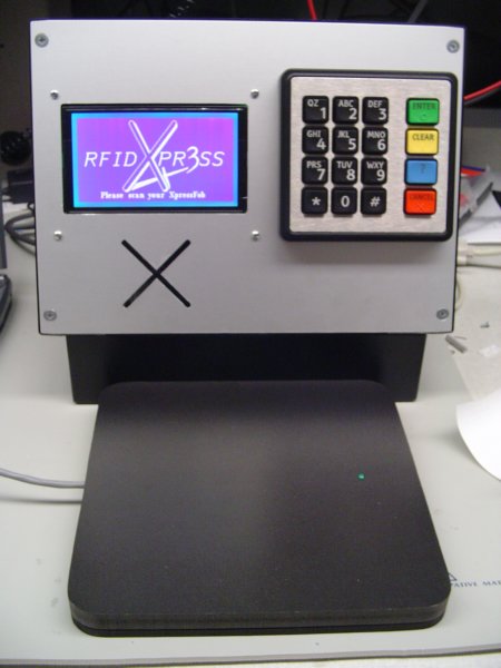
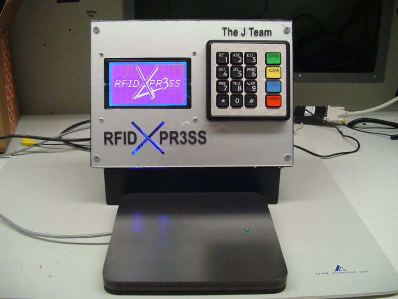
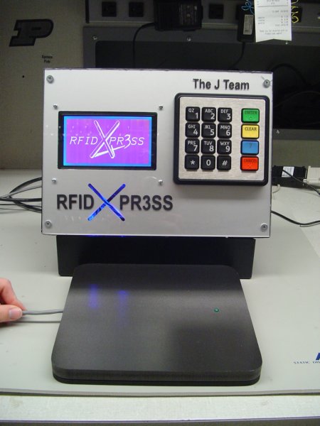
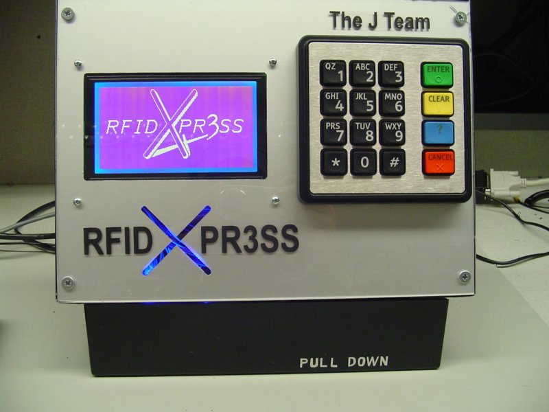
When we returned from the exam, Josh had brought the packaging, spray painted black,
and had mounted the whole design. Unfortunately... it didnt work. The keypad was acting erraticly. After much discussion, we had
Jonathan tighten the wire crimps, and we soldered a new ground header to the PCB in the PLD expansion slot. We then attached the
a grounding wire to the header and a screw attached to the aluminum face of the packaging. After grounding the chassis, it worked
perfectly. Images of the finished product (minus a few desired cosmetic dress-ups) can be seen below.
April 21, 2006 (4 hours):
We re-taped our PSSC video in one continuous session today. The packaging is
finally complete, so it looks a lot better in the video. It turned out to be about 3 minutes long, and it will be pretty easy
to edit into specific sections.
I came back later with a piece of acrylic that I bought at Home Depot. Josh and I cut
the acrylic to fit the entire case, and we drilled the appropriate holes in it. We then mounted it on the case, and it looked
awesome. Josh accidentally screwed one of the large screws too tight, and a small spider crack appeared near the upper right
of the front. It's not a big deal, so we'll be alright.
April 22, 2006 (2 hours):
Jennifer and I went to Radio Shack today and bought some blue LEDs. We then
returned to the lab, only to learn that LEDs we bought weren't very bright. We spent a long time trying to think of a good way
to rig them up to the chassis, and we couldnt really think of anything. What we really need is a brighter set of LEDs. We'll
go back to Radio Shack later and buy the brighter ones.
WEEK 15 SUMMARY
Accomplishments: Fixed the RS232 Transmission problem. Finished the packaging. Filmed the PSSC
Videos. Attempted to put cool blue light into our cool case.
Weekly Work Total: 17.5 hours
Project Work Total: 210.75 hours
Week 16
April 24, 2006 (3 hours):
I spent the night editing the PSSC video for class tomorrow. I only had
Microsoft Movie Maker at my disposal, but I guess it does a decent job... You can watch it here
if you'd like...
April 27, 2006 (4 hours):
Jen and I finally made it back to Radio Shack to pick up the mighty blue LEDs.
We tried a bunch of different configurations, but nothing was really easy. In the end, we decided to just solder a resistor to
one lead of the LED, and then we crimped connectors onto the resistor and the other lead and simply wired them to 5 V and Ground
directly. Now the "X" cut out of the case glows a funky blue. It does however shine directly in the eyes of a person standing
in front of it... maybe we can bend them to a less obtrusive angle later... We also printed out some labels onto decal paper
and affixed them to the front of the case.
April 28, 2006 (2 hours):
Jen and I finished the User Manual tonight. She had already written most of it
but I helped her finish it and edit the final version. Check it out below.
RFID Xpr3ss - User Manual
April 29, 2006 (5 hours):
I worked a long time on fixing up my papers for the final report. I also began
compiling everything together and started to linearize the references. This is going to be a lot of work...
April 30, 2006 (12 hours):
I spent literally my entire Sunday working on this mammoth paper. I pity the
teams who waited until today to start... Anyway, the editing took forever, and the references needed to be completely reworked,
the software didnt format nicely... So basically it wasnt fun, but it is now finished and the final product is beautiful. Check
it out below...
RFID Xpr3ss - Final Report
WEEK 16 SUMMARY
Accomplishments: Finished almost all of the papers due Monday. Still need to finish the poster...
Weekly Work Total: 26 hours
Project Work Total: 236.75 hours