Line Tracking for Assembly-on-the-fly
The goal of this project is to develop a vision-guided, visual servoing, robotic system that can operate on a moving assembly line. With full automation of work cells without stopping the assembly line, the proposed system can save huge amount of manufacturing resource by replacing "Stop-stations" where robots work in a stationary and fully calibrated environment. This technology can be used in lug nut securing, stamping, wheel decking, and glass decking "on-the-fly."

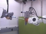

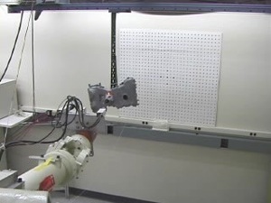
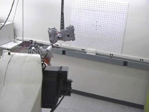
Figure 1: An example of stationary assembly station in a factory floor
For this task, we developed a distributed control architecture with vision inputs of multi-level accuracy. Our architecture for the proposed system is subsumptive and hierarchical, in the sense that each control loop can add to the competence level of the loops below, and in the sense that they can present a coarse-to-fine gradation with respect to vision sensing. At the coarsest level, the processing of sensory information enables a robot to become aware of the approximate location of an object in its field of view. On the other hand, at the finest end, the processing of stereo information enables a robot to know more precisely the position and orientation of an object in the coordinate frame of the robot.

Figure 2 Hierarchical, distributed look-n-move control architecture for visual servoing
At each level, the architecture allows multiple redundant vision loops to run concurrently and independently. A control arbitrator ranks the results of each loop according to certain confidence indices, which are derived solely from the sensory information. By letting the control arbitrator to choose control input from multiple redundant vision loops, the system shows a high level of fault tolerance and efficient usage of distributed computing resources.
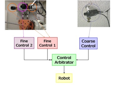
Figure 3: Proposed control architecture for our system and cameras used for visual inputs
The current implementation of the architecture consists of three visual loops: one coarse motion control and two fine motion controls as depicted in Figure 3.
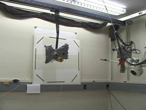
The coarse control module, as the name suggests, is responsible for providing an approximate location of the target object that can be used to guide the robot end-effector to the vicinity of the object. In our system, imagery from a camera mounted on the ceiling is used for coarse control. This camera can observe the entire robot workspace. The coarse control module applies a simple threshold to segment out the target object from the input scene captured by the ceiling mounted camera. Figure 3 shows the ceiling mounted camera used by this module. Figure 4a shows an example of what the camera sees as the object moves into its field of view.
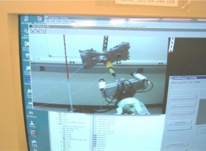
(a) Coarse control screen shot (b) Fine control screen shot
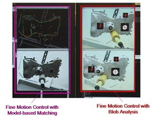
Figure 4: Screen shots of the visual tracking modules in our system
The fine control consists of two modules working in parallel, one blob-analysis based and the other model-based. As shown in the right side of Fig. 4b, one fine control module tracks three circular features in two stereo images taken with cameras mounted on the end-effector. The module uses simple thresholding to segment out the prominent blobs, rank-orders the blobs according to certain criteria, and, finally, selects three blobs with the highest scores in each of the two images. Stereo triangulation formulas are then used to calculate the 3D coordinates of the centers of the object features that give rise to these blobs in the two images. These 3D coordinates are used to estimate the pose of the target object. This module runs at 60 frames per second -- 30 frames for each image of the stereo pair -- and estimates the pose of the target with an average error of 0.7 mm and 0.3 degree.
The other fine control module uses a model-based pose estimation scheme for tracking the target. A wire-frame model of the target that consists of straight-line segments is used for pose estimation (on the left side of Figure 4b). It first projects the model on to the input scene with respect to the initial pose that is given by the coarse control module. Then, it sequentially matches the straight-line features in the model to the edges in the scene for an updated calculation of the pose of the target. For robust pose estimation, it uses a backtracking scheme for feature correspondence search. This module runs at 15 frames per second with an average error of 8.5 mm and 1.7 degree.

CURRENT TEAM
• German Holguin
• Johnny Park
FORMER TEAM’S MEMBERS
• Guilherme N. DeSouza
• Youngrock Yoon
• Jae Byung Park
• Hyunkseong Kwon
• Donghun Kim

• Single fine control loop
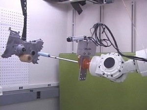
Video 1: Movies show the accuracy of coarse and fine controls. Laser pointer is locked on a small spot on the target surface while tracking.
Video 2: Robot end-effector keeps a constant relative position from the target while tracking [mpeg1] [mpeg2]
• Dual fine control loops
In order to show the enhanced robustness of our system, we manually created non-cooperative conditions while the system performs the peg-n-hole motion. Our system was tested under three non-cooperative conditions: (1) a part of the target object was occluded; (2) a spot light facing the object was repeatedly turned on and off; and (3) combination of the conditions (1) and (2). Under all three conditions, the fine control module with blob analysis often lost track of the object while the module with model-based matching continued to track the object. It was evident that the control arbitrator was able to adaptively select the most reliable control input at times of disturbance since the motion of the robot end-effector was smooth during the entire assembly process. Video 4 shows the performance of the system under all three conditions.
Video 4: Peg-n-hole demo with additional fine tracking module shows high level of fault tolerance to occlusion and sudden change of illumination condition [wmv]

Tommy Chang, Tsai Hong, Michael Shneier, German Holguin, Johnny Park, Roger Eastman, "Dynamic 6DOF Metrology for Evaluating a Visual Servoing System,," NIST/ACM/IEEE Performance Metrics for Intelligent Systems Workshop, PerMIS2008, August 19-21, 2008. [pdf, 0.35MB]
Y. Yoon, J. Park, and A. C. Kak, "A Heterogeneous Distributed Visual Servoing System for Real-time Robotic Assembly Applications," in Proceedings of the Int. Conference on Robotics and Automation, 2006. [pdf, 0.28MB]
Guilherme N. DeSouza and Avinash C. Kak, "A Subsumptive, Hierarchical, and Distributed Vision-Based Architecture for Smart Robotics," IEEE Transactions on Systems, Man, and Cybernetics -- Part B: Cybernetics, Vol. 34, pp. 1988-2002, October 2004. [pdf, 0.5MB]
P. Mittrapiyanuruk, G. N. DeSouza and A. C. Kak, "Calculating the 3D-Pose of Rigid Objects Using Active Appearance Models," in Proceedings of the Int. Conference in Robotics and Automation, 2004. [pdf, 0.2MB]
Y. Yoon, G. N. DeSouza and A. C. Kak, "Real-time Tracking and Pose Estimation for Industrial Objects using Geometric Features," in Proceedings of the Int. Conference in Robotics and Automation, Taiwan, 2003. [pdf, 0.2MB]
R. Hirsh, G. N. DeSouza, and A. C. Kak, "An Iterative Approach to the Hand-Eye and Base-World Calibration Problem," Proceedings of the IEEE International Conference on Robotics and Automation, Seoul, May 2001.