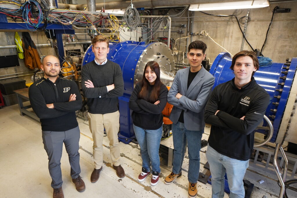
Wind Tunnels
The PETAL turbine facility can operate continuously and perform transients suited for accurate heat flux, performance, and optical measurement techniques. PETAL owns several modular wind tunnels: PT1, PT2, PT3, PT4, LOTUS and M250. The wind tunnels have several test sections to accommodate both fundamental and applied research, from low to high Technical Readiness Level (TRL). The test sections inlet pressure can vary from 0.5 to 6 bar, while the temperature can range from 270 to 800 K. Therefore, the resulting Reynolds number (Re) extends from 60,000 to 3,000,000, based on a characteristic length of 0.06 m. Our wind tunnels enable operations over a wide range of Reynolds numbers from Mach 0.05 to Mach 4.0, with mass-flow rates up to 70 kg/s.
PETAL Tunnel 1 [PT1]
The facility was conceived to operate over a wide range of Re and Mach numbers. The extension of the Re number envelope is defined by the operational limits of pressure and temperature. The test section inlet pressure ranges from 0.5 to 6 bar, while the temperature can vary from 270 to 700 K.Initially, all valves are closed. We begin the test by diverting warm flow to the mixer, which combines the cold with the hot stream. Along the cold and hot pipes, the control valves regulate the pressure level and mass flow. While the temperature is rising, the mass flow is purged to the atmosphere through the purge valve. Once the steady performance is achieved, the upstream pressure control valve sets the intended mass flow. When the operational pressure and temperature are achieved, the fast-actuated butterfly valve is triggered, driving a step in temperature on the test article. In order to ensure tightness during the hot flow operation, at temperatures around 700 K, special alloy seals were selected. The flow is discharged to the settling chamber, designed to deliver uniform flow conditions to the test section. Downstream of the test section, a sonic valve is used to set the pressure within the test section. The blowdown achieves steady conditions when the mass flow provided by the upstream high-pressure valves matches the mass flow set in the test section. To allow low Reynolds number testing, the test section and vacuum tank can all be set at sub atmospheric conditions. At such conditions, the test concludes once the sonic valve gets unchoked following the filling up of the vacuum tank.
PETAL Tunnel 2 [PT2]
The facility was conceived to enable testing of stationary and rotating turbine modules over a wide range of Re and Mach numbers. The test section inlet pressure ranges from 0.5 to 6 bar, while the temperature can vary from 270 to 700 K.Initially, all valves are closed. We begin the test by diverting warm flow to the mixer, which combines the cold with the hot stream. Along the cold and hot pipes, the control valves regulate the pressure level and mass flow. While the temperature is rising, the mass flow is purged to the atmosphere through the purge valve. Once the steady performance is achieved, the upstream pressure control valve sets the intended mass flow. When the operational pressure and temperature are achieved, the fast-actuated butterfly valve is triggered, driving a step in temperature on the test article. In order to ensure tightness during the hot flow operation, at temperatures around 700 K, special alloy seals were selected. The flow is discharged to the settling chamber, designed to deliver uniform flow conditions to the annular test section. Downstream of annular test section, a sonic valve is used to set the pressure within the test section. The blowdown achieves steady conditions when the mass flow provided by the upstream high-pressure valves matches the mass flow set in the test section. To allow low Reynolds number testing, the test section and vacuum tank can all be set at subatmospheric conditions.

PETAL Tunnel 3 [PT3]
The PT3 facility is a state-of-the-art, open-return continuous wind tunnel located at the Purdue Experimental Turbine Aerothermal Laboratory (PETAL). Designed to support high-fidelity aerothermal experimentation, PT3 is powered by a robust 300-horsepower fan capable of delivering mass flow rates up to 9 kg/s. Under these conditions, the 23 cm x 17 cm test section can reach Mach numbers as high as 0.8, enabling a broad range of subsonic and transonic investigations relevant to turbine and aerodynamic research. To support advanced flow control studies, PT3 is equipped with a custom-designed heated air injection system, which allows precise regulation of a secondary air stream into the main flow.
M250 Rig


In the quest for shorter development time and earlier entrance into service, a more rapid sequence of technology readiness levels is deemed essential. In these circumstances, modular engine facilities have the potential to facilitate an accelerated progression and reduced time-to-market of new, clean aviation propulsion concepts. In light of this scenario, the M250-C40B engine test rig, developed in collaboration with Rolls-Royce, is conceived to create an engine-relevant testing environment for the experimental assessment, development, and validation of gas turbine components and diagnostics, suitable for high-TRL testing in a variety of research topics of interest for novel gas turbine-based technologies.
The layout of the M250-C40B turboshaft engine provides excellent access to the combustor and high-pressure components, being especially suited for the study of combustor-turbine interactions, the integration of disruptive combustion technologies, such as pressure gain combustion, and the evaluation of alternative and sustainable fuels. Furthermore, the gas turbine is coupled with an electric generator, serving as a potential development vehicle for turbo- or hybrid-electric propulsion architectures.
The facility is equipped with an electric power system, cooling and fuel supply systems, multiple control and test modes, integrated controls, and safety auto schedules, allowing continuous operation, for up to multiple hours. The rig contains a wide variety of sensors to inform its operation and performance, measuring mechanical and electrical power, shaft speeds, vibrations, and turbine temperatures, among others.
Current research activities encompass the integration of a hydrogen-fueled rotating detonation combustor (ROSE) in an open-loop configuration, to assess the impact of the flow unsteadiness and hydrogen combustion products on the turbine and engine performance. Additionally, successful operation has been demonstrated using 100% sustainable aviation fuel (SAF).
Liquid Orthogonal TUrbine Simulator (LOTUS)
The Liquid Orthogonal TUrbine Simulator (LOTUS) is a water table that offers a rapid and cost-effective method for studying unsteady supersonic flow physics, providing an alternative to traditional wind tunnel testing. By utilizing the hydraulic analogy, which draws a similarity between the behavior of a shallow water flow flow and compressible gas dynamics, the facility enables real-time visualization of 2D transient aerodynamic phenomena. The shock waves of air can be seen with the naked eye as the hydrualic jumps in water, where the Mach number for air is similar to the Froude number for water.
A thin film (~5 mm) of water flows at rates up to 300 gpm (for Fr = 6) over a 2 m^2 glass pane where 3D-printed test geometries, such as turbine blades or wedges, can be placed with magnets. This setup allows researchers to observe flow behaviors such as the shock dynamics occurring during the transition between subsonic and supersonic flow through turbines passages.
A shock generator which moves at speeds up to 1.5 m/s was added to simulate the effect of an oblique shock impacting turbine airfoils. This phenomena is particularly relevant for turbine-integrated rotating detonation engines. A camera is mounted above to capture quantitatively the water flow patterns.


