Facility for Instrumentation and Open-Jet Research (FIOR)


The PETAL team places a strong emphasis on studying instabilities within transonic flows, making high-fidelity in-house calibration of aerodynamic sensors in high-speed flows essential for obtaining accurate and reliable experimental data. To mitigate potential blockage effects inherent to linear wind tunnels, the open-jet configuration is frequently utilized. FIOR features an exit diameter of 80 mm, operates across a range of Mach numbers from as low as 0.05 to sonic conditions, and supports continuous operation for several hours, enabled by the air storage capabilities at Zucrow Laboratories.
The open-jet’s size allows simultaneous calibration of multi-head rakes at various Mach numbers within a single day. This includes directional multi-hole sensors such as five-hole probes, total pressure Kiel probes, single and multi-wire thermocouples, constant-temperature hot wires, and fiber probes. Moreover, FIOR facilitates the study of external aerodynamics in transonic flows and the evaluation of film cooling schemes’ effectiveness.
A KUKA KR6 R700 robotic arm ensures precise six-axis traverse of instrumentation probes, supporting applications like creating calibration maps across different yaw and pitch angles. Additionally, techniques such as Schlieren imaging, Laser Doppler Anemometry (LDA), Infrared (IR) thermography, and other optical diagnostics enable high frequency detailed investigations of flow structures within probes or airfoils under low speed to transonic conditions.
Linear Experimental Aerothermal Facility (LEAF)
PETAL supports turbine research across the entire TRL spectrum, from concept demonstration (TRL 1-2) to multi-component interaction and full engine testing (TRL 5-6). LEAF is the low-TRL test section where the development of innovative technologies occur. It has a 17×23 cm rectangular cross section with full optical access on all walls and a robust stainless steel frame that enables testing beyond typical conditions for fully accessible facilities. A URANS-optimized conditioning nozzle ensures uniform inlet flow, with spatial and temporal uniformity validated through PIV measurements.
LEAF integrates with PT3 (continuous suction tunnel) and PT1 (high-pressure blowdown tunnel), supporting supra- and sub-atmospheric discharge at subsonic, transonic, and supersonic speeds up to Mach 5. Its unparalleled optical access has enabled a wide range of advanced diagnostics, even in combination, including high-speed Schlieren and Shadowgraph, backlit imaging, 3-axis Laser Doppler Velocimetry, Planar Mie Scattering, Planar Laser-Induced Fluorescence, Particle Image Velocimetry, Infrared Thermography, and Streamtrace oil visualization.
LEAF has driven and is driving novel research and patents in diverse topics, including heat-dissipating fins for bypass ducts, ammonia cycle heat exchangers, secondary flows in high-Reynolds airfoils, supersonic jets in crossflow, acoustic streaming in supersonic boundary layers and bladeless wavy turbines. Flow control and instability studies are central to LEAF and PETAL, and a nitrogen-pressurized injection system is integrated with LEAF, which has been used for controlling attachment and separation in transonic humps through blowing.
To bridge low- and high-TRL research, LEAF has been modelled using high-fidelity LES simulations in combination with various test articles (e.g., transonic hump and high-Reynolds airfoil). PETAL is currently investing in the synergy between computational and experimental research to accelerate design innovation and high-TRL implementation through reduced-order modeling and data assimilation.


Big Rig for Aerothermal Stationary Turbine Analysis (BRASTA)


Gas turbines operate at extreme temperatures and pressures, constraining the use of both optical measurement techniques and probes. A strategy to overcome this challenge consists of instrumenting the external part of the engine with sensors located in a gentler environment using numerical inverse methodologies to retrieve the relevant quantities in the flowpath. An inverse heat transfer approach is a procedure used to retrieve the temperature, pressure, or mass flow through the engine based on the external casing temperature data. An improved Digital Filter Inverse Heat Transfer Method that consists of a linearization of the heat conduction equation using sensitivity coefficients was validated in the BRASTA module, with flow temperatures up to 500K.
Particle Image Velocimetry (PIV) is a well-established technique for determining the flow direction and velocity magnitude of complex flows and successfully tested in BRASTA to study a scaled-up turbine vane geometry within an annular cascade at engine-relevant conditions. Custom optical tools such as laser delivery probes and imaging inserts were manufactured to mitigate the difficult optical access of the test section and perform planar PIV. With the use of a burst-mode Nd: YAG laser and Photron FASTCAM camera, the frame straddling technique is implemented to enable short time intervals for the collection of image pairs and velocity fields at 10 kHz. Different Mach and Reynolds number operating conditions were achieved by modifying the temperature and mass flow. With careful spatial calibration, the resultant velocity vector fields are compared with Reynolds Averaged Navier Stokes (RANS) simulations of the vane passage with the same geometry and flow conditions. Uncertainty analysis of the experimental results is also presented and discussed, along with prospects for further improvements.
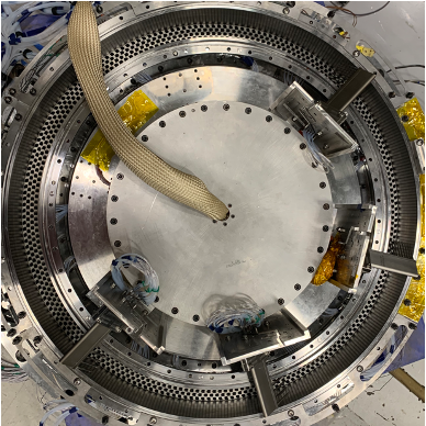
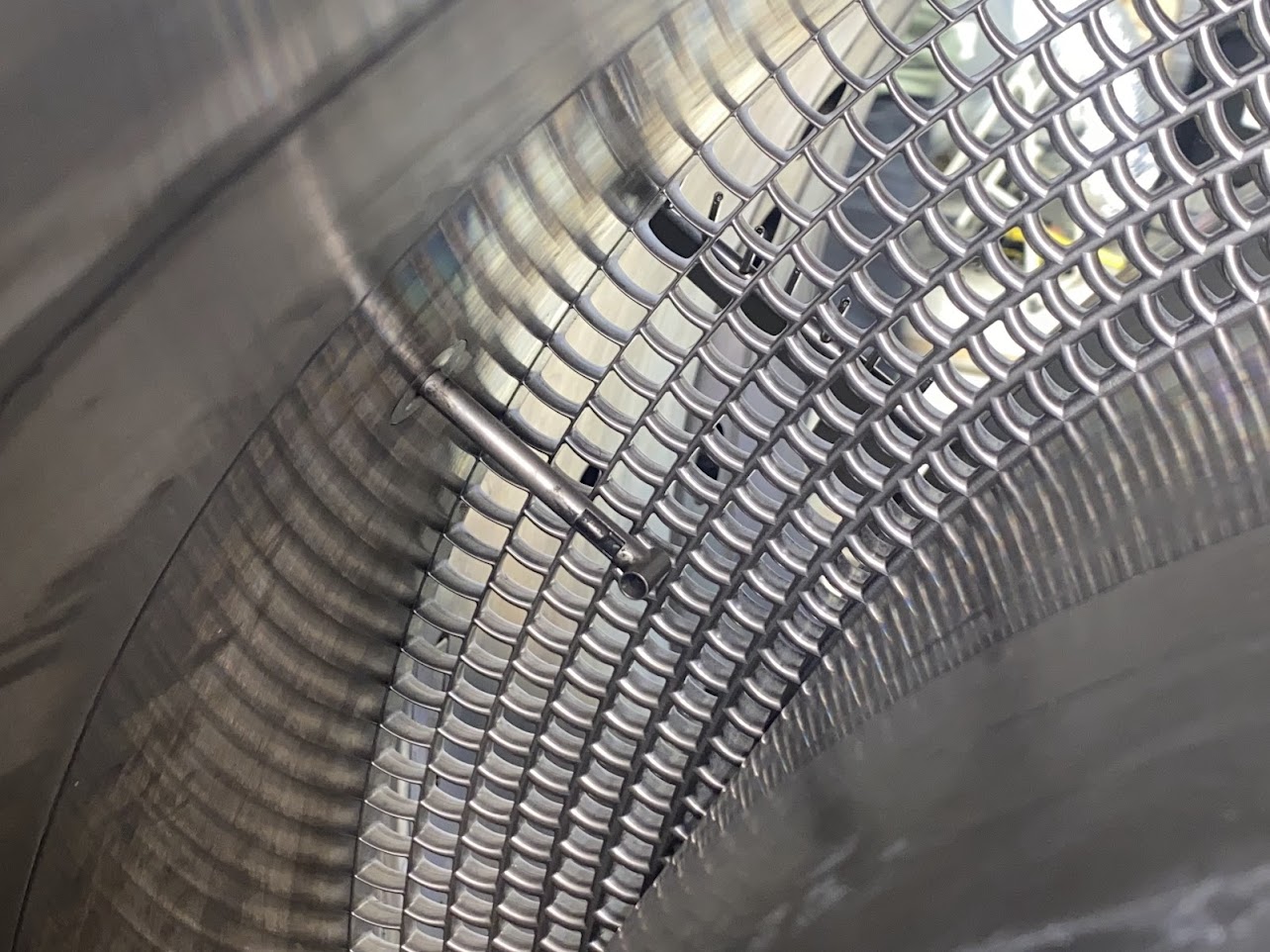
Annular Multi-frame turbine Blade Rig for Aerothermal analysis
A single flow conditioning gauze equipped with numerous radial and circumferential blades replicates the total pressure and whirl angle radial profiles experienced by a turbine blade in its relative frame. This setup bridges the gap between linear cascades and rotating turbine facilities while maintaining high-resolution measurement techniques and optical access. To ensure homogeneous inlet profiles, the positioning of the gauze relative to the turbine is informed by results from 3D steady Reynolds Averaged Navier Stokes simulations. The final design was machined as a single piece of stainless steel. The inlet flow quality was assessed using total pressure probes and static pressure taps around the annulus; the total pressure, whirl angle, and Mach number profiles downstream of the gauze were examined using Kiel and Five Hole probe traverses, showing good agreement with the required design conditions, thus confirming the viability of this configuration to a turbomachinery experiment. Future test campaigns can integrate rainbow annular cascades to test multiple geometries simultaneously, while performance studies can extend beyond five-minute blow-down test durations, allowing for high-resolution complete circumferential traverses. The turbine exit Reynolds number can range from as low as 30,000 under vacuum conditions to 1,000,000 when exhausting to atmosphere, with the ability to independently adjust the pressure ratio for testing across a range from low subsonic to sonic speeds.
Rotating Detonation Open-Loop Steady-State Engine (ROSE)
Rotating Detonation Combustors (RDC) have the potential to significantly enhance efficiency, minimize emissions, and enable the downsizing of engines used in propulsion and power generation. ROSE is a hydrogen-air RDC that was designed for future integration with a Rolls-Royce M250-C40B turboshaft engine, replacing the traditional deflagrative combustor and demonstrating the capability to couple the highly dynamic exhaust flow from an RDC to high-pressure turbines.
The ROSE hardware consists of a heatsink and an air-cooled configuration, both capable of independent testing from the M250 engine. The heatsink design focuses on understanding the various loss mechanisms within an RDC flow passage. It features a high degree of modularity, allowing for discrete adjustments in combustor geometry to examine the effects of inlet and outlet boundary conditions, as well as fuel injector stiffness, on aerodynamic performance and detonation wave dynamics. This configuration supports engine-representative testing conditions and facilitates parametric studies to define the combustor’s operational envelope.
The air-cooled design addresses the challenges of thermal management in an RDC environment by evaluating the performance and durability of different materials under extended operation. It introduces dilution air, cooling circuits, and a transition element to maintain steady-state operation of the RDC. Additionally, it ensures proper mixing of RDC exhaust products with cooling air, effectively matching the turbine inlet profiles of the M250-C40B engine.


Small-core Turbine Aerothermal Rotating Rig (STARR)
The development of efficient small core turbines is critical as the aviation industry pushes to higher OPR engines, hybrid propulsion concepts, and multi-stream engines. In response to the small core advancement, the Small Turbine Aerothermal Rotating Rig was designed to address small core turbine challenges. Its two-stage turbine module is designed for continuous and transient operation, enabling precise efficiency and heat flux measurements. The test section is designed to test both uncooled and cooled geometries with 15 different cooling configurations. The modularity of the rig allows for experiments to be performed in any stator-rotor configuration. The rig is equipped with two traverse rings, where different types of probes can be installed to measure temperature, pressure, flow direction, and Mach number. In addition, specially designed blade track inserts allow for a wide range of instrumentation and optical measurement techniques at the rotor tip of both stages. This includes PIV, PSP, low/high frequency pressure sensors, and tip clearance capacitance probes. These measurements will facilitate the detailed study of aero-thermal tip flows at various operating conditions.
The facility is complemented with a auxiliary cooling system, which can provide multiple gases including N2, CO2, or dry air, providing coolant and control fluids with a large variability of density and blowing ratios. The energy extracted from the turbine is absorbed by a direct drive (no gearbox) high speed AC electric motor, enabling engine representative transient operation. The STARR test section, built in collaboration with Rolls-Royce, together with its auxiliary systems is the state-of-the-art facility to evaluate efficiency in small core turbines at a TRL of 5-6.