|
|
|
|
|
|
Andrea's Research |
Monika's Research
|
OverviewThis section provides a brief summary of the main fluid power research
topics performed by Andrea Vacca’s group. Goals of the activities span
from the numerical analysis of innovative components and the
development of novel testing methodologies to the study of control
aspects related to hydraulic systems. Studies concerning a proper
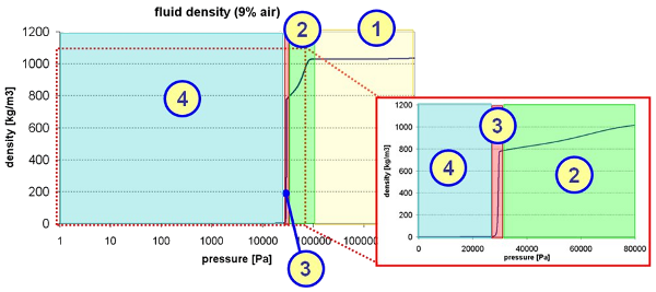
modeling of fluid properties have been performed as well. Research Topics: |
|
|
External Gear Pumps/Motors
HYGESimThe main result of the research activities in external gear machines is given by the simulation tool HYGESim. HYGESim (HYdraulic GEar machines Simulator) is a numerical model for the simulation of external spur gear pumps and motors. Conceived at University of Parma (Italy) with the support of the company CASAPPA, HYGESim is currently developed at MAHA Fluid Power Research Center. The simulation tool consists of different modules: a lumped parameter fluid dynamic model, a mechanical model for evaluation of the gears motion (considering also the micro motion of the gear axes of rotation) and a geometrical model. The first two models are implemented within the LMS Imagine.Lab AMESim® simulation environment, with proper submodels written in C language, while the geometrical model is implemented developing proper macros capable to read directly the CAD3D drawings of the unit (pump/motor).
The simulation tool is characterized by an accurate description of the geometry of the different components (i.e. teeth’s profile, design of sliding elements) and it is able to calculate the movements of the gears’ axes of rotation resulting from the forces exerted on both gears. Potentials of the model are represented by the prediction of the main features of flow through the machine (such as the inter-teeth meshing pressure, the evaluation of possible cavitation onsets, pulsation of flow at the external ports, etc.) and the detection of the wear of the casing due to the possible contact between the gears and the casing. The tool is currently used for the analysis of the main phenomena related to the operation of the machine, for the optimization of its design and for the research of innovative solutions. Variable-Displacement Gear PumpGiven the importance of efficiency in any mechanical system, in recent years, displacement control of pumps has gained a lot of attention in the field of fluid power. Gear pumps have a lot of advantages in that they are of simple design, fewer moving parts, easy to maintain and very compact. However, gear pumps available in the market today are fixed displacement. By allowing variable displacement, the advantages of gear pumps can be utilized in wider applications. The project aims to demonstrate the commercial viability of a Variable Displacement Gear pump using a novel principle. The idea of changing the displacement is based on varying the timing of the connections of the Tooth Space Volumes (TSV's) with the inlet and outlet grooves. We achieve this by introducing a movable element, called "slider." In traditional pumps the grooves are machined onto the lateral bushings. The slider element allows us to change the position of the inlet and outlet grooves with respect to the TSV's. 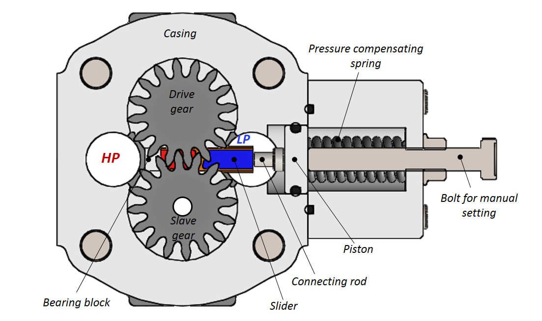 For this project, a parametric optimization to increase the displacement reduction of the gear profiles was performed in modeFRONTIER. The performance of the optimized pump was simulated in HYGESim. The project aims to build prototypes for different pressure applications. One for high pressure (~200 bar) and another for lower pressure (~15 bar). The high pressure prototype has been built with a pressure compensated design. It was tested and the prototype was able to implement the pressure compensation principle. Currently the design of the low pressure prototype is being finalized. This prototype will be capable of electronic displacement control. This is achieved by controlling the slider position using an electro-mechanical actuator like a solenoid or stepper motor. |
|
|
Gear Ring (Gerotor) Units
With the support of MAGNA Powertrain the developed models have been
successfully validated with experimental results for different pump
designs for both, steady state and transient pump operation. |
Multimedia:Downloads: Videos:
|
|
|
Systems/Components ModelingVarious activities have been performed concerning the modeling and testing of hydraulic systems and components (with particular reference to hydraulic valves). Some exemplifying projects are reported here (Download PDF). Concerning the valve modeling, the described projects show the capability of simulating not only the main phenomena related to the internal flow, but also the interaction between the internal parts (the mechanical elements and the electro-magnetical actuation system, if present) and between the other components present in the considered system. Moreover, the aspect related to the possible control strategies are accounted as well. In few cases, advanced optimization criteria have been used to improve current designs or to formulate new solutions. All developed models were validated on the basis of experimental measurements. For systems, the considered cases are pertinent to hydrostatic transmissions and to other hydraulic systems for mobile applications. In these cases, lumped parameters models were developed with the aim of analyzing the margin of improvements of current solutions and to design innovative systems. Hydraulic CraneIn order to perform an estimation of the energy consumption and possible improvements, a study was conducted on a reference crane by changing the settings. Two typical operating cycles were considered for the study, in order to investigate the overall operation of the machine (lifting/lowering, with/without load). A detailed AMESim model, created to model the behavior of the valve, supported this activity. After extensive testing, it was found that the energy consumption on the crane was indeed significantly reduced by the inclusion of the new control structure.
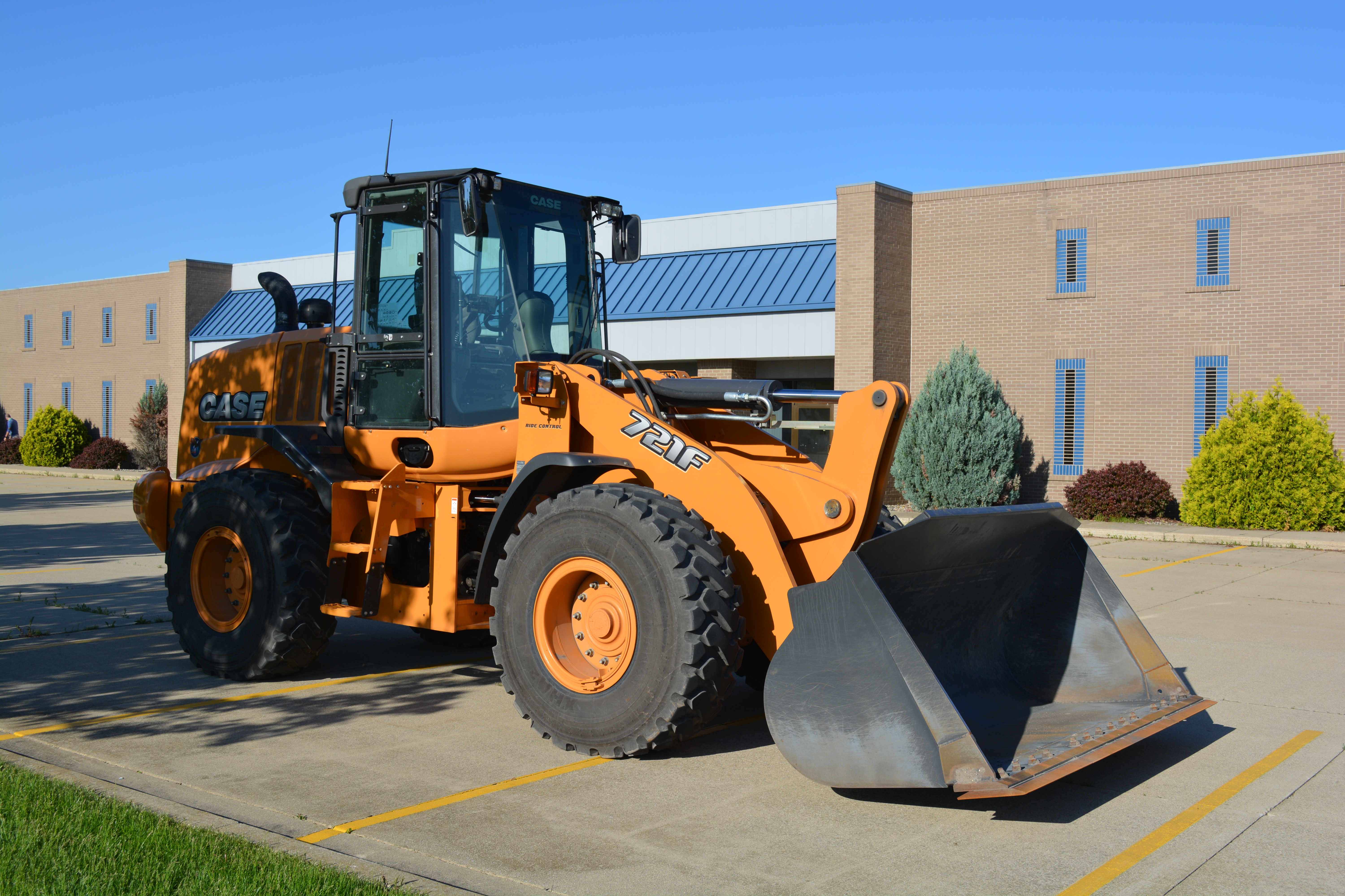
Mobile Hydraulic ApplicationsAlong with the testing of the control structure for vibration reduction on the hydraulic crane, applications in mobile hydraulic machinery have also been considered. The specific machine which was considered for this implementation is a wheel loader. Much like with the crane, computer simulations were conducted using a model of the wheel loader to determine the viability of using actuator motion to damp system vibrations. After the simulations showed positive results, experimental tests were conducted on a wheel loader. These tests have indicated that the control strategy is also capable of damping vibrations in mobile hydraulic applications.
|
Multimedia:Downloads: Videos: |
|
|
|
|
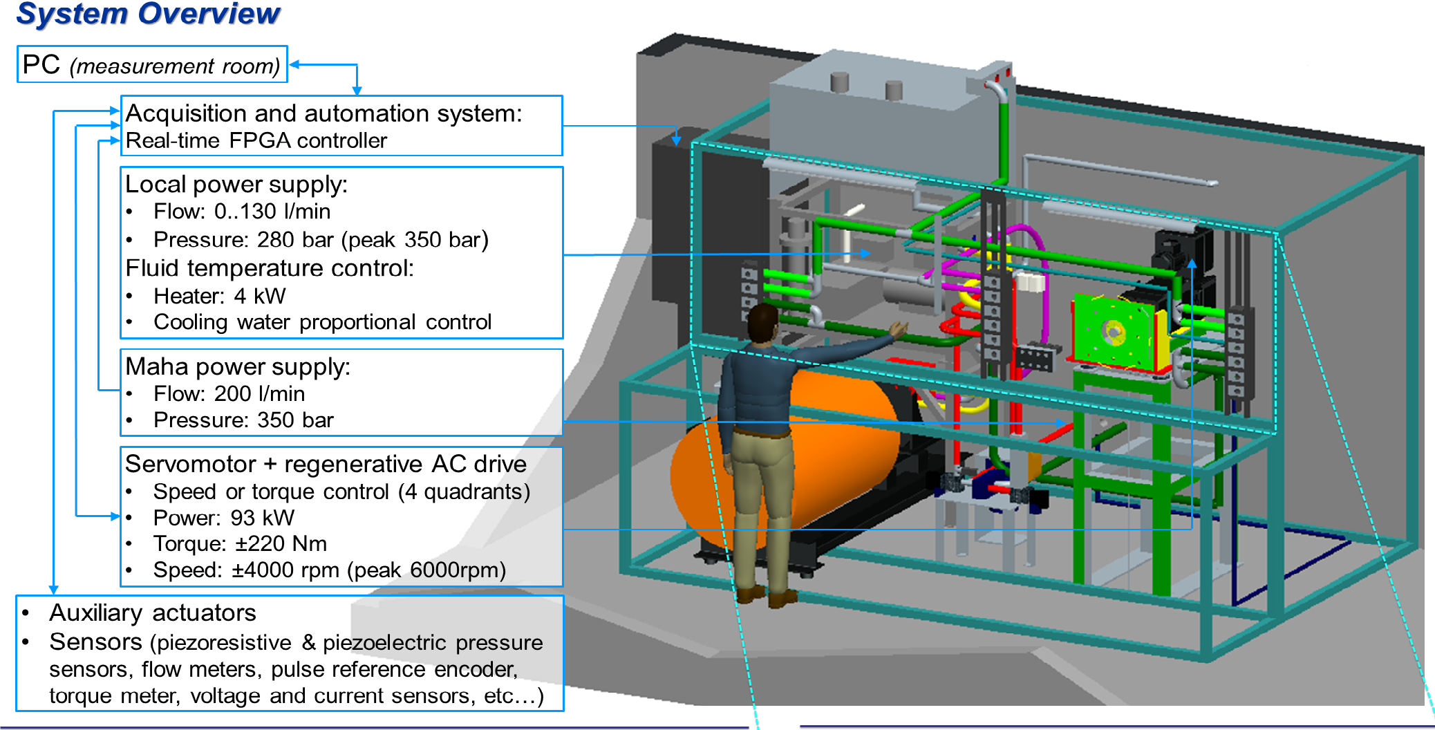
Multi-Purpose Test Rig for Automatic Components Testing
Main features of MPTR are:
|
|
|
||||
|
© 2013 Maha Fluid Power Research Center | All Rights Reserved. |
||||
 Various projects have been performed in the area of
external gear units. Purposes of these projects are: the development of
accurate simulation models; the proposal of new solutions characterized
by better efficiency and lower noise emissions; the development of
innovative testing techniques. More details about these project are
reported here (
Various projects have been performed in the area of
external gear units. Purposes of these projects are: the development of
accurate simulation models; the proposal of new solutions characterized
by better efficiency and lower noise emissions; the development of
innovative testing techniques. More details about these project are
reported here (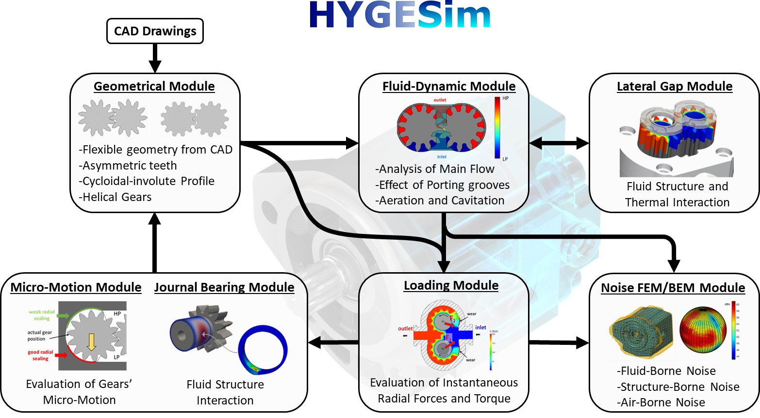
 In cooperation with
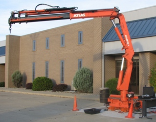
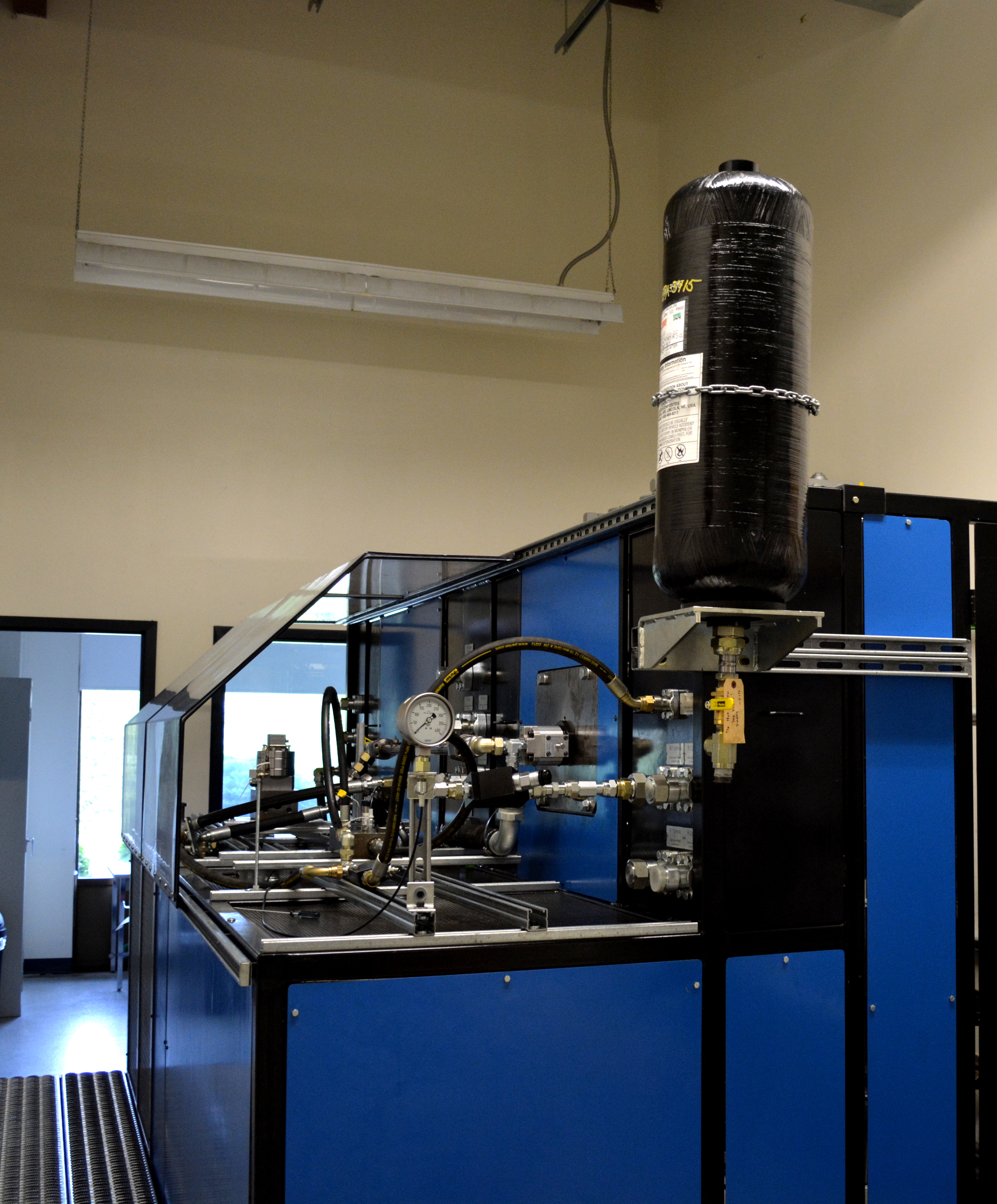 MPTR is a versatile test
rig for the automatic characterization of hydraulic systems, including:
hydraulic pumps, motors, valves, actuators, and compact systems.
The protective enclosure safely groups the parts constituting MPTR.
From the outside, MPTR presents a working area to support the systems
under testing and a series of hydraulic ports used to supply them, as
well as a speed/torque controlled driveline. Once the test system is
set up, experiments can be safely performed by the adjacent measurement
room, provided with large window on the MPTR room and emergency stop
button.
MPTR is a versatile test
rig for the automatic characterization of hydraulic systems, including:
hydraulic pumps, motors, valves, actuators, and compact systems.
The protective enclosure safely groups the parts constituting MPTR.
From the outside, MPTR presents a working area to support the systems
under testing and a series of hydraulic ports used to supply them, as
well as a speed/torque controlled driveline. Once the test system is
set up, experiments can be safely performed by the adjacent measurement
room, provided with large window on the MPTR room and emergency stop
button.