John Doherty's Lab Notebook
Week 01
January 9, 2013 (1 hour):
Met as a team after class to discuss preliminary project proposal.
January 10, 2013 (2 hours):
Met as a team after class to finish writing preliminary project proposal.
WEEK 01 SUMMARY
Accomplishments: Submitted preliminary project proposal.
Weekly Work Total: 3 hours
Project Work Total: 3 hours
Week 02
January 16, 2013 (2 hours):
Met as a team to write final project proposal and develop PSSCs for presentation. Started developing a parts list to genenerate a rough project budget.
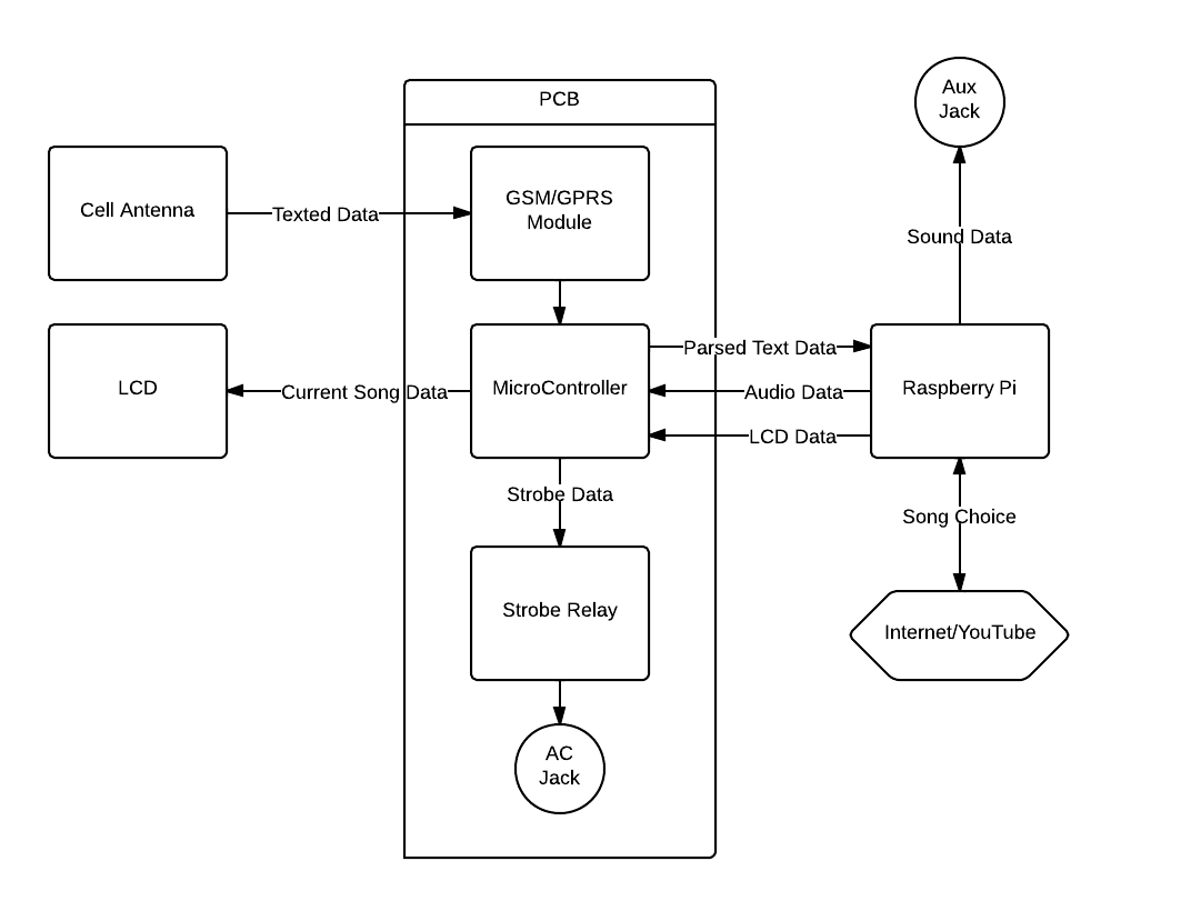
We came up with the following block diagram and split up the workload based on the main functional units(sms module, server-side, power, strobe lights).
WEEK 02 SUMMARY
Accomplishments: PSSC and project proposal finalized.
Weekly Work Total: 5 hours
Project Work Total: 8 hours
Week 03
January 23, 2013 (2 hours):
Worked as a team to finalize the PSSC's based on feedback from course staff and peers. Decided to implement the DMX512 protocol to control strobe lights. Also decided to add an SD card slot to allow users to upload files with preferences:
-Blacklist and white list for songs
-Wifi settings
-Lighting preferences
-Sound effect files
Original plan was to add a camera, to increase hardware on device, but the camera just did not fit with the goal of the project. The SD card is much more practical.
January 24, 2013 (2 hours):
Completed homework 2.
WEEK 03 SUMMARY
Accomplishments: Homework 2 and updated PSSCs. Finalized major functionality
Weekly Work Total: 4 hours
Project Work Total: 12 hours
Week 04
January 29, 2013 (5 hours):
Worked on constraint analysis and started looking at parts for our major pieces of functionality. Found GSM Module and investegated DMX512 protocol and implementation. Looked, but could not find a DMX512 reference in Potter.
GSM Module requires UART and an separate SD card slot. Basic opperations for sending and receiving SMS messages is fairly simple. Should investigate more complex features like the ability to buffer messages. We are not expecting an overload of text messages, but with lights requiring more timely processing, it is probably better to hold received texts until thet can be parsed. Here are some good references:
- This site talks about Arduino, but is a still a good referernce.
- This site lists commands that can be sent over UART.
Also looked into details of DMX512 protocol. Decided we could send DMX control signals using UART, with a voltage regulator. Some important details about the DMX512 protocol:
- Uses RS-485 standard to define electrical properties
- Must send a signal every second
- Lights are daisy chained, so one DMX port on our device could theoretically control 512 lights (hence the 512 in DMX512)
- Lights are addressed seqentially, and packets are sent to consecutive addresses.
- Need to find a way access the actual protocol document which is for sale for $50.
February 1, 2013 (1 hour):
Met with group from management class to discuss how collaboration for their business plan. They brought a different perspective looking at the project from a marketing stand point. There were clearly some points were the requirements for our projects were not entirely compatible. Overall collaboration seems like it could add to both of our projects.
WEEK 04 SUMMARY
Accomplishments: Completed constraint analysis and part list. Met with management team
Weekly Work Total: 6 hours
Project Work Total: 18 hours
Week 05
February 6, 2013 (2 hours):
Ordered major components after class:
- 6 sample microcontrollers from Atmel
- RaspberryPi
- GSM Module and board connector
- SIM Card slot
- SD Card Slot
- DMX converter and female connector
- LCD display
More detailed parts may need to be oreder later. Did not order analog components or LEDs for the box.
Set up our lab station and logged into the computer.
WEEK 05 SUMMARY
Accomplishments: Ordered parts. Packaging design
Weekly Work Total: 2 hours
Project Work Total: 20 hours
Week 06
February 11, 2013 (1 hours):
Downloaded EAGLE on personal computer to practice with. Walked through Sparkfun PCB schematic and tracing tutorials.
February 12, 2013 (2 hours):
Ordered more parts including voltage regulator for the power supply. Looked into hardware associated with GSM module and started drawing up a schematic.
Also found some good resources:
- Breakout board schematic
- GSM Module Hardware Spec
- GSM User Manual
Also found better SIM slots:
SIM4050
SIM4055
February 13, 2013 (3 hours):
Worked on schematic for the GSM Module. Researched circuits involved in GSM module and SIM card reader. Need to order a SIM cardreader and electrostatic discharge IC still. SIM card reader requires a good deal of protection from ESD. Created the following circuit from the GSM Module hardware guide in Eagle:
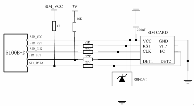
Still need to make SIM card slot in EAGLE.
February 13,2013 (6.5 hours):
WEEK 06 SUMMARY
Accomplishments: Ordered parts. Packaging design. Completed some custom footprints and circuits in EAGLE
Weekly Work Total: 12.5 hours
Project Work Total: 32.5 hours
Week 07
February 18, 2013 (5 hours):
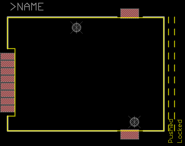
Worked on preliminary layout of parts including rough parts positioning and overall size of board. Made some changes to the schematic. Some of the considerations for the parts layouts are:
- Slots (SD, SIM) need to be in the back of the device for easy access.
- Most DMX circuitry needs to be in the back of the device to avoid long connections between DMX female connector and DMX driver.
- GSM module should be as isolated as possible. It uses an unusual power supply and has high and quickly varying current requirements which could generate significant noise. Additionally, the module itself will be the be receiving and transmitting RF signals which could generate more noise despite shielding.
- GSM module needs to be on edge of the board so antenna can attach to side of the device.
The image below shows the current state of the layout without any traces.
February 19, 2013 (6 hours):
Prepared for TCSP on preliminary PCB layout. Moved headers for debugging microcontroller to the area surrounding the microcontroller. This will allow for easier access when debugging and if any modifications or additional features need to be added after the PCB has been manufactured. Moved all individual components including resistors and transistors into locations that will make routing as easy as possible. I have started considering routes for power and ground, but most of the tracing has not been done. Considerations for the traces are as follows:
- Circuits with different voltage requirements should be separate.
- Power supplies should be as close as possible to final destination to reduce noise
- Traces for the power source for the GSM module should be around 50 mils because of potential 2A draw. This number is certainly on the safe side, but it without prior experience with PCB design this is the best approach.
- All other power supply traces should be thick but not necessarily as thick as GSM module traces. Other power supply traces will be about 30 mils.
- Large ground and power planes will be used to reduce source and ground immpedances.
Another note related to power supplies is the need for heat sinks. The only voltage regulator that could potentially use a heat sink is the 3.8V regulator for the GSM module which could at times provide as much as 2A. If the supply was a constant 2A, a heat sink would be necessary, but because the 2A spikes are very intermittent, it will not be necessary.
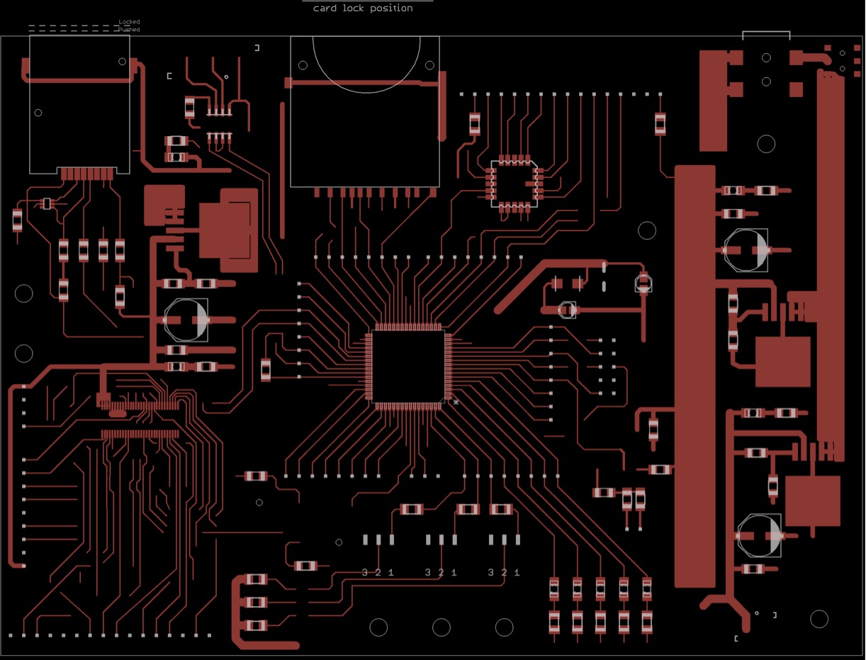
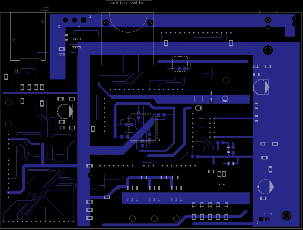
Here is an image of the current state of the layout and traces. Not all traces are complete, but power and ground are in place.
February 21, 2013 (6 hours):
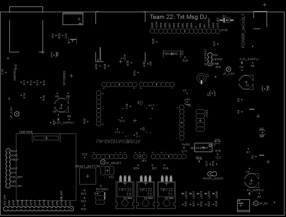
Modified PCB layout from TCSP feedback and competed all traces. Moved decoupling capacitors for the micro to the bottom side of the board. The PCB is still in a preliminary stage, so it needs to be double checked for functionality and acute angles. All electrical connections have been made and all footprints match. Design was completed with previously stated considerations in mind. Below are some images of the final layout.
WEEK 07 SUMMARY
Accomplishments: Completed preliminary PCB Layout. All parts placed and traces and ground planes in place. Just need to verify all footprints and circuits
Weekly Work Total: 17 hours
Project Work Total: 49.5 hours
Week 08
March 3, 2013 (5 hours):
Prepared for design review. Finished PowerPoint slides and related design review documents. Prototyped more circuits to have a better understanding of component operation before design review and final PCB submission. Attached GSM module and microcontroller to breakout boards:


March 5, 2013 (3 hours):
Built and tested equalizer circuit. Ran simple arduino program to verify operation. Values of a particular band pass filter will be output initially after strobe, and must be read then. Continuously reading the same band without strobing is not possible. Minimum time constraints are also necessary to operation. See data sheet. The circuit is identical to PCB circuit, so that circuit should function properly. Still no luck getting microcontroller or GSM module working. Also placed a new parts order, which should include all remaining parts. Only parts in order that are on the PCB are screw terminals which should not cause an issue.
March 7, 2013 (6 hours):
Verified all schematics and traces on PCB. Note that slots for power jack are on the millings layer and are oval shaped. These cannot be drilled in drill file, but are included with submission in a .mil file. Also made silk screen look good. Generated gerber files and got them verified using FreeDFM.
FreeDFM Report

Final Silkscreen:
March 7, 2013 (0.5 hours):
Final check through PCB, with TA verification. Submitted PCB.
WEEK 08 SUMMARY
Accomplishments: Submitted PCB! Microcontroller programmer works. Equalizer circuit verified.
Weekly Work Total: 9.5 hours
Project Work Total: 59 hours
SPRING BREAK
Week 09
March 19, 2013 (2 hours):
Looked into SD Card reader. Circuit has already been designed and matches those used in similar sample projects. Need to port the FatFS library to our microcontroller. This library will allow us to read from a FAT file system on the SD card. This feature is necessary if we are to modify the contents of this SD card with any computer. Modifications to this library should be straight forward and they provide sample code for AVR microcontrollers. It will just require slight tweaks to port it to our specific micro. Continuing to learn details of programming AVR microcontroller.
March 24, 2013 (6 hours):
We received the latest parts order, so I had a chance to start working with the new GSM module and shield. We still do not have a compatible SIM card, but I was able to start communicating with the unit over UART, using an Arduino. I was able to establish serial communication and send and recieve messages through the terminal. I used the screen command in the terminal to monitor the output of the GSM module as well as send messages serially to the unit. The module correctly booted on power up and sent signal strenght information. With the shield, the GSM module itself is removeable, so were able to test the old module which must have been fried at some point during our initial test.
Because there is not a lot of meaningful functionality in the gsm module without the SIM card, we ordered a basic preloaded, pay-as-you-go SIM card. This card has the ability to communicate on the 2G spectrum that we need. It also means we don't have to pay for features that we are not using like data and talk. This SIM card should arrive in 3 days.
An interesting feature I found about through this process was the screen command line program. This program has lots of features, but lets you communicate with any terminal device including an external serial device like the Arduino. The commands used for this were:
stty -F /dev/ttyUSB0 cs8 115200 ignbrk -brkint -icrnl -imaxbel -opost -onlcr -isig -icanon -iexten -echo -echoe -echok -echoctl -echoke noflsh -ixon -crtscts
screen /dev/tty.usbmodem 9600
The first command sets up the port. The second command runs screen on the arduino with 9600 baud rate.
An additional note: When using the device with a SIM card we cannot use the 5V supply from the Arduino. The GSM module can require up to 2A a certain periods, and the Arduino can only supply 1A. We will have to connect the 5V input of the shield and the VIN of the Arduino to a regulated 5V input capable of supplying the necessary current. We can just use the voltage source at the lab station because we are just doing this for prototyping purposes.
Porting this to our micro should be fairly straight forward. The only necessary communication between the module and the micro is UART. We will be able to just send the same UART commands to perform the desired operation.

GSM shield is shown on the left. Some of Kyles PCB soldering work is shown on the right.
March 28, 2013 (3 hours):
Worked more on getting SPI and SD card slot working, was not able to make much progress and I'm still learning the micro and how to browse the documentation. Started looking into getting LCD working to practice with SPI. Eventually got shift register working with SPI.
WEEK 09 SUMMARY
Accomplishments: Established communication with GSM module. Started looking into SD card stuff.
Weekly Work Total: 11 hours
Project Work Total: 70 hours
Week 10
March 30, 2013 (5 hours):
Got SD card slot working with FAT file system. Still a couple of minor issues with reading files, but I was able to create the drive and create a new file on the SD card. This involved porting the FatFS library and example AVR code to our micro controller. It was fairly straight forward. The library implements all the FatFS code in a device independent manner, so that the user just has to modify the code for the physical layer. Luckily they had done most of the work involved with implementing the SD protocol as well, so it was mostly a matter of adjusting port pins and adjusting the SPI setup. It also required me to setup a timer interrupt. This should be fairly easy to integrate with other microcontroller functionality. If memory requirements become an issue, it should be straight forward to implement the minimal version of the FatFS library which includes less functionality, but which should be fine for our purposes.
April 1, 2013 (3 hours):
Received the TMobile sim card in the mail and wanted to get something working. To facilitate rapid prototyping, I just setup the Arduino with the GSM shield and the proper power configuration. I was able to connect to the T-Mobile network, noting the the US GSM code is 7.
It was straight forward to send the AT+ commands serially to the GSM unit. When setting up the shield with the Arduino, it is important to keep in mind that the Arduino cannot supply 2A, so I used our 5V regulator to supply voltage to the Arduino and the shield.
The first test I ran was making a simple phone call. This involves a single command with the phone number.
Sending an SMS message was a bit more complicated and involved putting the module into a specific text mode, but otherwise sending messages is simple as well.
The next step is to receive messages. Here there are two options: have messages forwarded automatically to the Arduino or have the GSM unit store the messages until they can be read. The second option sounds more logical for our use. We can setup an interrupt to fire when a new message has been received. Then we can receive and parse the messages.
Another note: RIO/GPIO46 is a pin used to detect a new SMS message. It will go low for a period of 200ms and then return high. This pin is not connected to the micro currently, but is wired to a header that could be fly-wired to a GPIO pin on the micro.

April 4, 2013 (5 hours):
Worked on getting gsm module working on PCB. First issue was finding the correct baud rate for communication. According to the data sheet the default baud rate should be 115200, but I found an Arduino tutorial for the module in which they used 9600 baud rate. This is what I used and communication worked. The first problem I ran into was that I had no easy way to debug the communication because Atmel studio only displays memory values in hex instead of giving the option to show ASCII. I needed a way to see the characters being returned so I merged the GSM project with the SD project so that I could write to a file on the SD card like a debug log. While this is not ideal it gets the job done effectively.
After getting that issue with resolved, I saw that the GSM module was sending the command "+SIND:0" which means that the SIM card was not being detected. The circuit and soldering seemed fine so I compared our PCB to a SparkFun breakout board for the module. It turns out the GSM module uses a 6-pin standard for the SIM card and I had implemented the 8-pin standard on the PCB. Fortunately this was a simple fix and involved fly wiring two pins on the SIM card slot together and then tying one additional pin to ground. With this fix the GSM module was able to effectively detect the SIM and connect to the network.
WEEK 10 SUMMARY
Accomplishments:
Weekly Work Total:
Project Work Total:
Week 14
April 7, 2013 (7 hours):
Got sending and receiving SMS messages to work. Was even able to parse out phone number from received message and send a reply message to that number. Decided on a communication pattern between the GSM module, the microcontroller, and the RaspberryPi.
- GSM module is configured to forward received SMS messages to the microcontroller over UART.
- Microcontroller has interrupts established on the GSM UART RX port. Whenever new data arrives from the GSM module, it is buffered and eventually processed.
- When the micro receives a SMS it parses it and sends it to a transmit buffer to be sent over UART to the Raspi. (Packets sent to and from the Raspi will be of a special format discussed below.)
- Raspi will send commands and data back to the micro in a similar fashion and it will be received in a buffer and parsed.
Data packets used for communication with the RaspberryPi will be of the following pipe delimited format:
<command>|<arguement 1>|<arguement 2>...
for example:
SMS|<phone number>|<message>
SD|<file name>|<contents>
Currently the GSM to micro link is almost implemented but it should not be difficult to extend this to the link between the Raspi and micro.
April 8, 2013 (2 hours):
Spent some time cleaning up the code and separating different functional units into different files. This will be easier to maintain than keeping code in one long file as we were doing before.
April 11, 2013 (3 hours):
Spent a few hours trying to get the LCD working. Still getting nothing on the screen. The code is the same as examples from the internet and matches commands and specifications from the data sheet. Added some recommended initialization code, but not getting any response from the LCD. It could be a hardware issue or something wrong with the LCD.
WEEK 14 SUMMARY
Accomplishments:GSM module can now send and receive text messages. Alsoworked on getting LCD to work, but no luck so far. SMS control is a PSSC, so thats pretty cool.
Weekly Work Total: 12
Project Work Total:
Week 15
April 13, 2013 (5 hours):
I was able to get the LCD functioning. In the schematic we accidentally had an extra resistor on the contrast control header. This header was intended to be used for a potentiometer to adjust the contrast, but the lead that should have been connected to ground was actually connected to a resistor and then to ground. Because of this, the contrast input was ranging from 1.6V to 3.3V, when it should range from 0 to 0.3V. The LCD is now functioning, but still a little dim. We reduced the resistor values on the backlight LED, and it is visible and readable, but not as bright as we had hoped.
All the code was functioning otherwise, so I was able to print simple messages to both lines of the LCD. The LCD will be used to display the current song and the queue, so the current song will be displayed not the top line and the queue will be displayed on the bottom. Because a song name plus an artist name is generally longer than 16 characters, we will have to implement some scrolling to display all necessary information on the LCD. There are a few ways to make the display scroll:
- Use the built in scrolling functionality of the display.
- Scroll manually by printing different substrings of the desired string to the display
Ultimately the second option seems better. Using the built in scrolling functionality is easy, but both lines must scroll at the same time. Also each line can only contain 40 characters in memory, so it will be a challenge to display song names longer than 40 characters. The characters can be written fast enough that the second option should appear smooth and not require too many cycles.
April 15, 2013 (3 hours):
Was able to implement scrolling on the LCD display and an interface to make it easy to update the display data. Both lines scroll at the same rate, but independently from each other. This way, when one line reaches the end, it resets, while the other line continues to scroll. Initially had queue displayed simply as one long string, but realized that would require a lot of memory to transmit over UART and buffer. Instead, we decided to send each line of the queue independently and then display queue items one at a time. The interface seems natural and easily readable. I also combined LCD code with other microcontroller code for GSM and RaspberryPi UART. Was not able to test this yet, but it compiled.
April 17, 2013 (4 hours):
Ran into an issue when trying to demonstrate text message functionality to the TAs. The UART communication with both the GSM module and the RaspberryPi started behaving unpredictably. On occasions, it would receive full text messages and send them to the RaspPi, but generally it would not. Not much had changed except adding the LCD code. After some investigation, it seemed that the timer interrupts used for scrolling in the LCD code was actually interrupting interrupting the reception of UART data. The issue was difficult to discover, but the fix was actually fairly simple. Our microcontroller allows users to specify priority for all interrupts. I was able to set interrupts for any kind of UART data to high, and made everything else medium or lower. Things like LCD and SD card are not time critical so those were made low. Now everything seems to be functioning in the microcontroller code.
Also decided on an interface for sending LCD data to the microcontroller from the RaspberryPi.
To specify the current song:
CUR||<song data string>
To specify a song in the queue:
QUE|<queue position>|<song data string>
Also decided on a protocol for sending SD card data to the raspberry pi. When an SD card is inserted, it will send all the data from the blacklist and whitelist files, line by line, to the RaspberryPi using this format:
SD|<file>|<line data>
WEEK 15 SUMMARY
Accomplishments:
Weekly Work Total:
Project Work Total:
Week 16
April 21, 2013 (4 hours):
Implemented the interfaces described in previous entry. Everything seems to be working and the LCD can be updated from the RaspberryPi. Additionally, SD card data is being sent to the RaspberryPi. The reading of SD card data provided some issues initially because of an oddity in the FatFS library. Apparently file names are limited to rather short strings by default. These meant trying to read files with names like "blacklist.txt" and "whitelist.txt" would return strange errors. This was fixed by just using shorter names for these text files.
We also merged Kyle's code for all the strobe light and DMX code with my code for GSM, LCD, and SD card stuff. It seems to be working fine. Lighting code runs in the main loop because that has to be updated fairly continuously, but is not so critical that it should interrupt any other functionality. Fortunately, all other interrupts (GSM and RasPi UART, LCD timer) operate fast enough that they provide no noticeable lag to the strobing.
At this point the microcontroller code is nearly complete with a couple of tweaks.
WEEK 16 SUMMARY
Accomplishments:
Weekly Work Total:
Project Work Total: