Aditya Balasubramanianan's Notebook
Week 01
August 23, 2011 (1 hour):
Met as a team after class to discuss preliminary project proposal.
August 24, 2011 (2 hours):
Met as a team after class to further refine the project proposal and begin work on Homework_00. Discussed potential display technologies,
and the laser pico-projector used by the GHUD team last semester seemed to be a strong contender as it continually showed up in searches
online. Possible packaging considerations, and the use of mirrors to allow for better viewability was also discussed. Various telemetry
options were also discussed - GPS, Speed, G-force (accelerometer), rangefinder, compass were discussed. Also brought up the possibility
of having two on-board cameras - one for rear-view purposes and another for frontal night-vision purposes. While the idea was well recei
ved, we were wary of the actual implementation of cameras, and tabled the idea till further discussion was carried out with Dr. J.
August 25th, 2011 (1 hour) :
Met as a team to finalise and complete details on HW_00.
August 25th, 2011 (3 hours) :
Met with Blaine and Dr. J to discuss the project and throw some ideas around. See Blaine's notes here .
Also - initialised the shay.ecn.purdue.edu/477grp3 account, and created the website. Used Open Source Web Designs to obtain a nice, simple website template, and incorporated some of Blaine's
artwork into the design. Also integrated links to the Google Code website. Team notebooks were created, and instructions were posted
on the Facebook group on how to access and edit notebook files easily.
WEEK 01 SUMMARY
Accomplishments: Submitted preliminary project proposal, set-up the website and lab notebooks for the team, met with Dr. J and Blaine to
discuss some ideas, and researched alternative display technologies and their viabilities.
Weekly Work Total: 7 hours
Project Work Total: 7 hours
Week 02
August 30, 2011 (2 hours):
Met as a team to formulate PSSCs for presentation in class on September 7. Discussed possible motherboard options with the team, including
ARM, BeagleBoard, and Atom chipsets. The team primarily investigated Atom motherboards (as it may be possible to get Intel-sponsored funding
regarding the Atom Boards, and the BeagleBoard. The Beagle board was the next strongest contender after the Atom boards, because it has VGA
processing abilities, has dedicated camera connectors with drivers developed. Suggested using old netbook (personal) as initial Atom development
board, since it is currently not in use, and has a multitude of useful features including capacious battery life, easy rechargability and availability
of plug-and-play cameras. It would also be relatively easy to set up a script to parse the data we plan to log on the device, and translate it into
some sort of graphical representation on Google Maps or the like. The team also came up with an initial draft for the PSSCs, and the initial block \\
diagram. The team also agreed amongst themselves which sensors each individual should research.
August 31, 2011 (2 hours):
Researched various GPS sensors on sparkfun, and some additional embedded websites. Sparkfun contains by far the best documentation on different modules,
and even has a great GPS buying guide typed up on their website which can be found here. The two
modules that seemed the most faesible were the Copernicus module and the Venus module. The Copernicus is the technologically superior module, with lower
power consumption, more accurate capabilities, and a newer design. However its biggest weakness is its packaging - it is an SMD module with under-the-
chip pads, which is extremely difficult for us to implement due to solder reflowing needs. The Copernicus module is available in an eval-board package
with DIP headers. The Venus board also has under-the-chip solder pads, and also comes in an eval-board package, but without the DIP headers. It is unclear
from the pictures posted whether we would be able to solder our own headers on whether we would have to solder wire leads on (undesirable). Also, we were
unsure on whether we were even allowed to have DIP headers on our PCB, since it was highlighted in lecture that doing so would limit our board space. The
TA said that it is acceptable as long as we don't implement everything on our board in such a fashion - i.e. to a degree within reason. Ultimately, the
Copernicus is almost twice the cost of the Venus module ($80 vs. $50) - so before making our final decision we will consult a few internet forums to determine
the relative ease of use of the two modules, reliability and functional differences.
September 1, 2011 (2 hours):
Met as a team to finish the final project proposal - refined and finalized the PSSCs and block diagram. We also finished the project overview, and
abstract, and assigned individual responsibilites. The team went over and discussed some of the sensor options we found - unfortunately it seems that
a long range distance sensor (rangefinder) likely to not be possible due to shortcomings in ultrasonic technology, and the prohibitive cost of laser
distance sensing technologies. The team also realized that no-one was assigned responsibility for researching microcontrollers, which was quickly
remedied.
WEEK 02 SUMMARY
Accomplishments: PSSC and project proposal finalized. Narrowed down GPS modules for use on project. Explored alternative approaches to using
an Atom board, possibly from a cannibalized netbook.
Weekly Work Total: 6 hours
Project Work Total: 13 hours
Week 03
September 6th, 2011 (6 hours):
The team worked together to complete the Library creation part of the PCB tutorial. Also, an expendable helmet was obtained over the Labor Day weekend, so an
amount of time was spent in cleaning and prepping it for use. We tested the projector with the 'expendable' helmet/visor which was tinted, but not much difference
was seen over regular clear plastic. Also, the website experience a complete overhaul, and was reworked by Aditya Balasubramanian. The website now has more pages,
and more space for uploaded files/documents as the semester progresses. Lab-notebook links now exist throughout the website, and there is even a picture gallery
to showcase our project as it is being built. This move is in parallel with keeping the Google Code Wiki for code and other documents that are more technical in nature.
Also, the Copernicus GPS module and antenna were ordered today, as well as a new power supply for the soon to be cannibalized netbook. They should be expected to arrive later
this week. Some in-depth discussion was had with Blaine regarding the difficulty in implementing a commpass with regards to tilt compensation. It seems like a more effective
method of implementing a bearing calculation would be to perform a calculation on the GPS coordinates and go from there.
September 8th, 2011 (2 hours):
Discussed possibly using Windows Embedded 7 as the software enviroment on our Pico-ITX Atom based motherboard, therefore spent some time researching various VisualStudio
implementations of webcam use (heaviest overhead), and installed Visual Studio 2010 Professional (available for free with a .edu email account at
Microsoft Dreamspark
September 9th, 2011 (3 hours):
Met with Blaine and Chuck to decide on what Atom motherboard to order, and how to go about it. Orbit Micro offered a perfect match for our system
needs. A 1.1GHz Pico-ITX (roughly the size of a tarot card) form-factor board with a passively built, somewhat rugged case, 1 Serial COM port, 4 USB ports, audio out and an 8GB
bootable compact flash card and 2GB of 533MHz SODIMM RAM system is currently our system of choice.
Shortly prior to the meeting, Aditya stumbled upon some documentation from Denso Automotive, which mentioned the use of concave mirrors
in vehicle heads-up displays. This led me to more in-depth research regarding the use of concave mirrors/lenses in heads-up-displays. I found a Google Book on Cockpit engineering that illustrated this concept
well. Aditya also found some documentation regarding the chromatic properties of the optical "combiner" part of the heads-up-display, which can be found here.
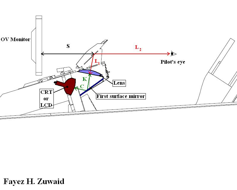
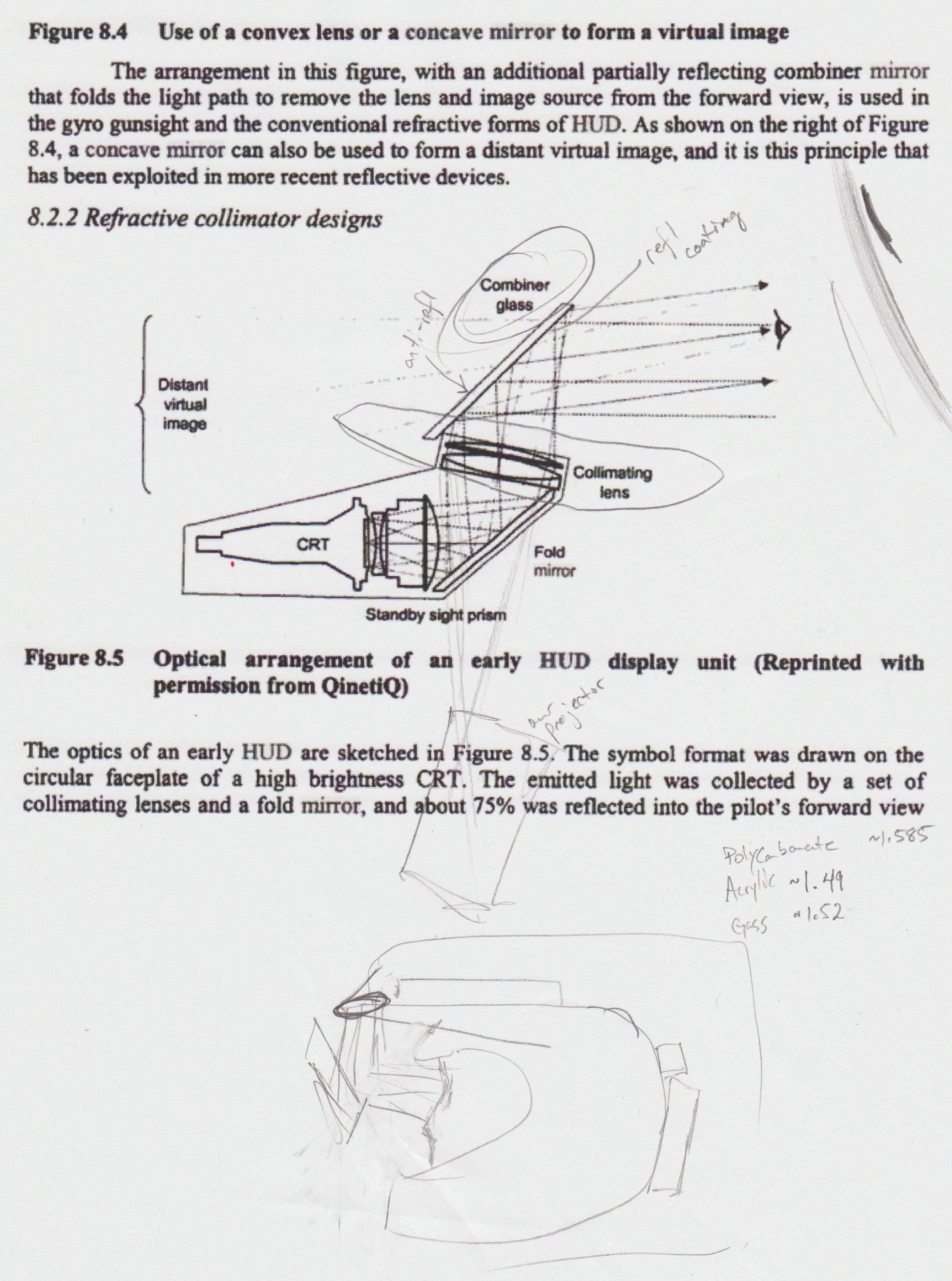
It was ultimately decided that we should consult with someone more familiar with optics, especially with regards to the specific design/dimensional calculations that need to be performed to determine
the most appropriate lens to use.
WEEK 03 SUMMARY
Accomplishments: Finished PCB tutorial, formulated plan-of-action to handle to optics part of the project (collimating lens for distant/'floating' HUD projection
and ordered sample microcontrollers. (Need to order dev tools!)
Weekly Work Total: 11 hours
Project Work Total: 24 hours
Week 04
September 12th, 2011 (5 hours):
May have found some optical combiner glass from Edmund Optics NT72-500. Further investigation
needs to be made as to whether this is exactly what we need. Source: Free Falcon Forums.
Began writing Design Constraint Analysis and preparing the TCSP presentation. Collaborated with team regarding content of report and focus of presentation.
September 13th, 2011 (4 hours):
Finished writing Design Constraint Report, and prepared TCSP presentation. Gathered some more information about HUD design and the components we plan to use. Discussed
various options for the power system on the device. It was agreed upon that a LiPo battery is probably the best option at this point. It was also suggested (Aditya) that
the microcontroller, sensors and projector all be powered by the USB ports on the from the Atom board, since the projector is designed to run off USB power, and it would
be fairly easy to regulate the 5V USB power rail to the 3.3V needed by the microcontroller and sensors. A debate between whether it would be better to have an off-helmet
charging system or not was carried out. On one hand, having the charging system on the helmet would allow for indefinite operation as long as a power source (12V DC from a
car, for example) was available. On the other, having the system off-helmet would free up space and weight. Another potential concern involving the on-helmet charging system
is that the battery would have to charge at the same time the system is under load. Aditya knows from previous research experience that this is less than trivial, and if done
improperly can cause damage to the battery both electrically and mechanically. The communication protocol between the Atom board and the microcontroller was also briefly
discussed. Took delivery of some Lexan and reflective window tint, to test out using that as visor material to project on to. It seems like a decent alternative, but there is still
too much light bleed for the solution to be viable in bright daylight - a combiner will probably still be needed.
September 15th, 2011 (2 hours):
Reviewed the feedback from the TCSP presentation and incorporated it into the final homework document. Also incorporated teammates' review and feedback into the
document. Window tint was fully cured at this point, so conducted some more testing with Blaine and confirmed previous suspicions of needed combiner glass. Gained
a good idea of how to work with Lexan and how to incorporate it into our design out of this exercise, which is good.
September 16th, 2011 (5 hours):
Spent most of the day researching and evaluating various power source and management solutions. Briefly considered using a 3.7V RC car battery pack and stepping up
the voltage to 5V for the Atom board. After talking to George H., he suggested a 7.4V battery pack instead (which the team was not aware existed).These seem ideal
for the team's needs. After researching some variants of a 7.4V 5000mAh battery pack, two things seem apparent:
- battery will have to be located off-helmet unless an extremely creative solution can be found due to size constraints
- battery charging system will also have to be off-helmet, because charging multiple cell batteries can be somewhat risky and difficult to manage electrically
Several SMD voltage regulator solutions were considered, and Aditya finally decided on the LM2592 by National Semiconductor. It is a high current switching regulator, configurable
to both 3.3V and 5V. It is a bit expensive, at $7 a piece, but it requires minimal additional components, takes up little space and has high current specifications, which
are required by the device. Both regulators are also switching regulators, so they are extremely efficient and will help prolong the operating time of the device while on
battery power. This design choice now needs to be approved by the rest of the team, and then the regulators, supporting components, battery and charger can be ordered. The team
may also have to look into harness and connector solutions to allow for easy user-access to the battery during operation.
WEEK 04 SUMMARY
Accomplishments: Tested window tint, finished the Design Constraint Analysis. Formulated a power supply system solution; just need to get it
approved by the rest of the team.
Weekly Work Total: 16 hours
Project Work Total: 40 hours
Week 05
September 19, 2011 (8 hours)>:
Blaine provided a quick walkthrough of some of the code management software he had implemented, and a quick overview of the
UART, ATD and pushbutton functionality he had implemented on the micro. Blaine and Aditya began to work together to get the GPS
module to work. According the documentation, the GPS was capable of a run-and-start, where all that was necessary was to connect it to Tx,
Rx, Vcc, and GND and it would work. As is the natural order of things, it was nowhere near that straightforward. The GPS TX/RX lines were
connected to the serial port on the lab desktops. After matching the BaudRates, very little output was seen, maybe a few characters.
A variety of different terminal programs were tried, and further consulation was made with the documentation. After adding some connections deemed
"necessary minimum connections" we managed to get more sensible data - it was in the NMEA string format expected, but it was still garbage.
September 20, 2011 (8 hours)>:
It was hypothesised that the UART interface was not playing nice with the desktop's serial port, so it was decided to try a USB-to-Serial cable that
Aditya had left over from ECE362. Unfortunately, it yielded the same results as the desktop. What was particularly confounding about the problem was that
the nature of the garbage output suggested that the baud rates between the terminal and device were mismatched, which was not the case, as all settings used
adhered to those specified in the documentation. Blaine had the idea of running the Tx/Rx lines from the GPS module, into the PIC32 eval board, through the
uController and into the desktop's serial port. This worked like a charm, and the GPS module was talking to the Trimble GPS studio without any issues.
The whole apparatus was then shifted to a door of the EE building, with the antenna just outside the doorway, and we were able to get over 5 satellite fixes!
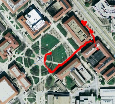
A battery powered apparatus was then jerry-rigged together, and Blaine and Aditya took it for a walk around the Engineering Fountain, using the Trimble Studio's
datalogging function to make sure the GPS was functioning correctly. The image below shows the test walk, and the path between the EE and ME buildings was chosen
to see if the module would lock between medium sized buildings.
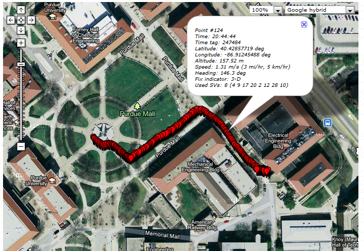 The rest of the day was spent making the schematic and PCB footprint for the PIC32 QFP-100 package in Eagle. The PCB footprint proved particularly challenging
because of the custom pad sizes and extremely small pin spacing. It took several attempts to get the pin spacing just right, as some of the measurements on the PIC32
datasheet weren't very clear.
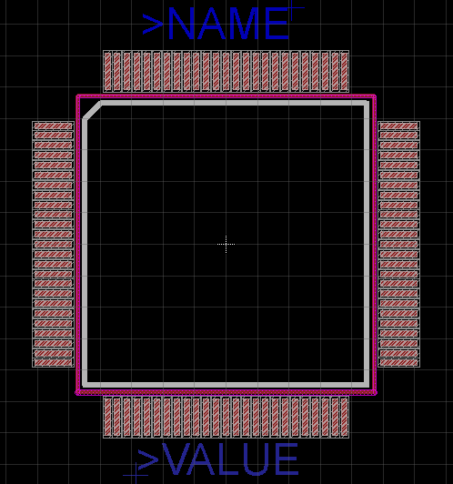
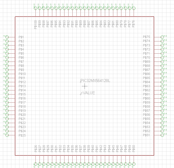 Preliminary work was also started on the schematic and footprint for the voltage regulator package (LM2592).
September 21, 2011 (4 hours)>:
The final packaging for the device was decided upon - see picture below.
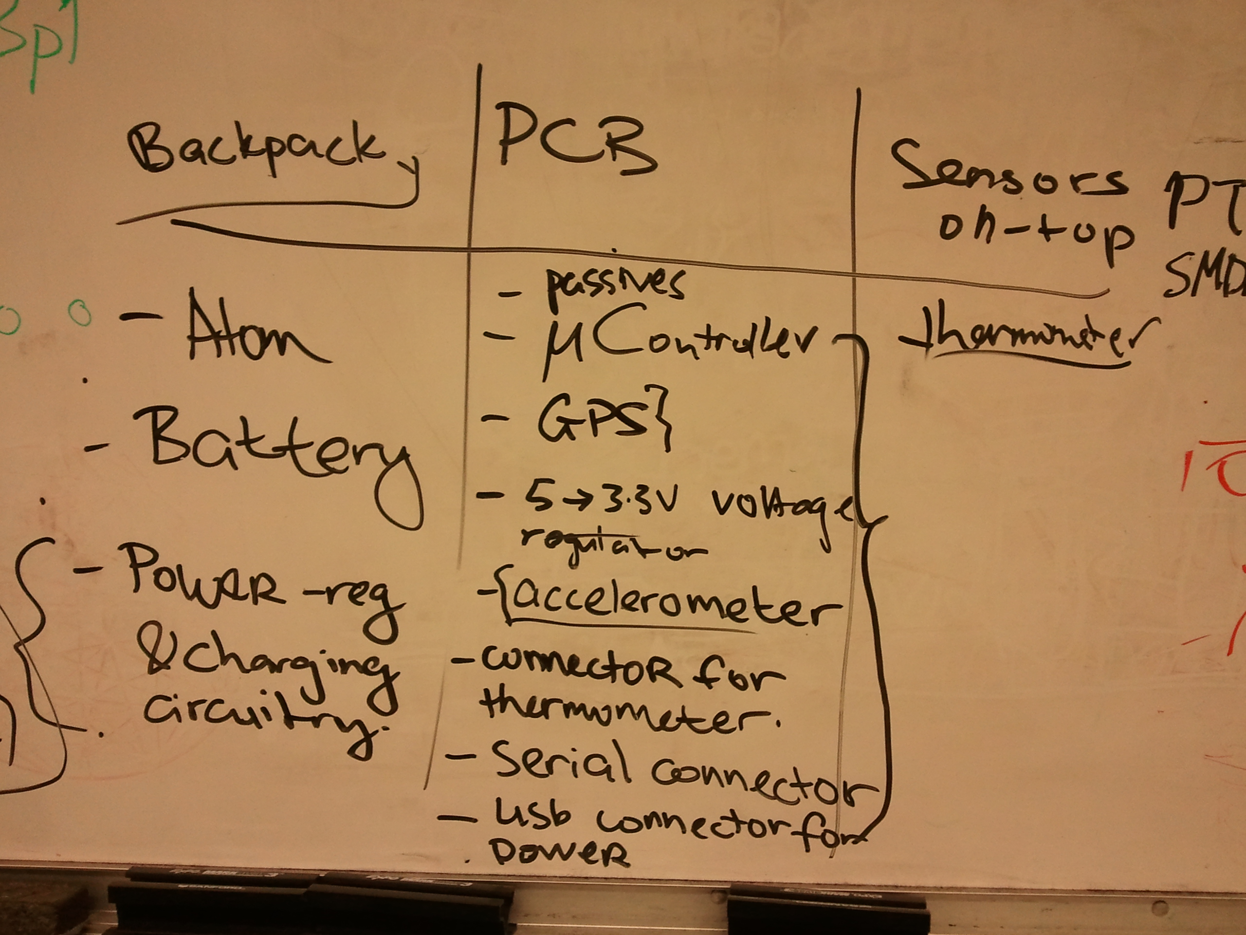
Due to the added weight of the battery, which is much larger than originally anticipated. This 7.4V 5000mAh battery
weighs almost 300g. Since it would have to be located off-helmet, it seemed logical to take the Atom board and put it together with the battery and a PCB with voltage regulating circuitry.
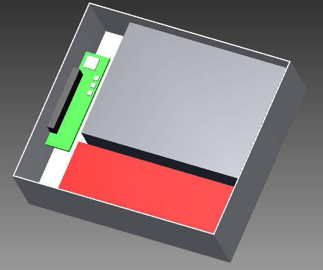
The remainder of the time was spent gaining familiarity with AutoDesk Inventor, with the objective of making a mockup of our off-helmet enclosure. AutoDesk proved extremely difficult to
install, with installs failing on both Aditya's laptop and the Lab Desktop. Installation was finally sucessful on Aditya's home desktop. Meanwhile, a second attempt at the installation was
executed on Aditya's laptop, using Autodesk 2011 instead of 2012. This succeeded. Initial mockups were made on the home desktop and appear below.
September 22, 2011 (5 hours)>:
After getting some feedback from the team, it was decided to revise the backpack unit. More specifically, to allow for easier access to the I/O ports, and perhaps some form of an
active cooling system, since the airflow over the backpack unit would be of a much lower volume. The revised design is pictured below.
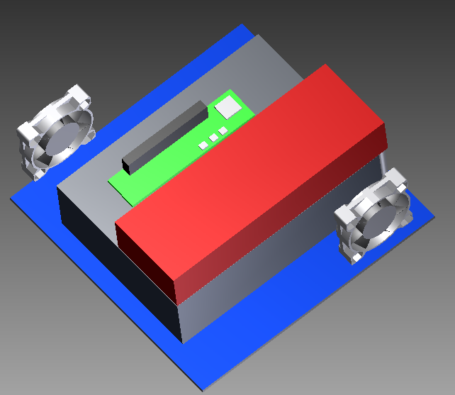
A drawing spec. sheet was also created, which can be viewed here: Final Drawing with Measurements.
September 24, 2011 (2 hours>:
Tried getting familiar with the Windows Embedded 7 toolkit and runtimes. Had a lot of trouble getting the runtime to install on a VirtualPC. Installation
failed several times, where the OS installed would hang. The installer is being left overnight to see if any progress is made after several failed attempts.
September 25, 2011 (3 hours):
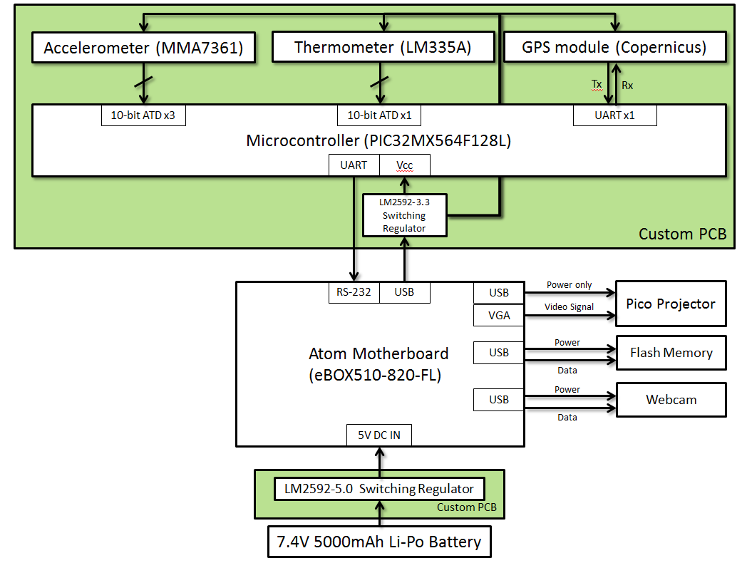
Updated the block diagram (seen below) to reflect some component choices and re-formatted it for HW5. Also completed PCB footprint for LM2592 switching regulator, and got familiar with the
Sparkfun Eagle Library which is quite extensive and useful - it has schematics and footprints for the majority of parts they carry!
WEEK 05 SUMMARY
Accomplishments: Worked with Blaine to get the GPS working and tested it out. Finished the microcontroller footprint and schematic creation, and
created CAD models for our off-helmet backpack unit. Began fiddling with Windows Embedded 7.
Weekly Work Total: 30 hours
Project Work Total: 70 hours
Week 06
September 26, 2011 (2 hours):
Discussed plans for a custom, integrated and functional harness solution between helmet and backpack unit - decided on DB25 (D-sub 25 pin) connector since 15-pin VGA pass
through is needed. Began intial schematic work on backpack unit PCB. Also made some changes to the power circuitry. Decided to go with a 3A, 5V regulator at the Li-Po battery,
and a 5V->3.3V linear regulator at the microcontroller board. This is because the microcontroller and sensors draw so little power, it renders the efficiency of the switching regulator
moot. Since the linear regulator is so much cheaper, it was selected as the alternative. Further research on battery options was conducted.
September 27, 2011 (5 hours):
Sketched an intial schematic for the backpack PCB, seen here.
Spent some more time finalizing the power circuitry design, and specifics on the DB-25 connector to be used. Spent some time with Marcelo going over the optical challenges and
brainstorming solutions. Without the aid of custom optics or a custom MEMS solution, it seems very likely that we may not be able to acheive collimation as originally planned. This
means our image will not 'float' as was originally hoped, but the combiner glass still seems promising. Worked with Nikhil to finish the preliminary schematic work - Nikhil worked on
the primary PCB schematic, and Aditya worked on the PCB schematic for the backpack unit.

Finished the TCSP presentation and majority of HW05.
September 28, 2011 (5 hours):
Gave the TCSP presentation, and received some good feedback regarding our schematic (presented schematics below).
The main concern voiced was our lack of battery fuel gauge and battery recharging circuitry. Initially it was
thought that we would simply charge the battery externally using an off the shelf charging station, but it would
be awesome if it were incorporated into the design. The need for a fuel gauge though, was not something that could be
avoided. It was needed for the following reasons: 1) to ensure the battery does not fall into deep depletion, where the
cells are drained so low, that it causes damage to the batteries 2) to ensure that if a low-battery situation arises, the
system has some way of knowing about it, so that it can safely power down and warn the user in advance 3) to monitor the battery
health status during use, so that the user maybe alerted of any battery failure or fault conditions. Having not considered this at all
thus far, very little information was known to the team at this point. However, Team 4 came to the rescue, and suggested a charging IC and fuel
gauge solution which they were using in their project, that might have been useful to us. Work was started on re-writing the TCSP to accomodate the
latest design changes to the schematic, to incorporate the battery management circuitry. It was intially decided to use the ICs suggested by Team 4.
The ICs suggested by Team 4 were : the MCP73213 for the charging controller, and the DS2782 for the fuel gauge (communicates to micro via I2C)
September 29, 2011 (8 hours):
Before lecture, it was discussed and decided that we should move all of our circuitry to the backpack unit, leaving only the temperature sensor, rear-view camera
and display tech on the helmet. This is because our charging circuitry now needs 3.3V power sources, as well as to communicate with the microcontroller, so it really
doesn't make sense to have so many data and power busses going between the helmet and backpack unit when they could all be located together. This was brought up with Prof.
Meyer, and agreed with the team's concerns.
Spent some time with Nikhil going over the latest plans for the power circuitry. While Nikhil worked on updating the PCB library to accomadate
the new ICs, some time was spent going over the component selection sections of the datasheets for the battery management ICs.
Finally managed to get WinEmbedded7 installed on the dev-netbook (donated by yours' truly). Installed the 'full' version which is basically the same as 'Windows Starter 7'
but supposedly without the bells'n'whistles (which is odd, considering WE7 comes with Paint and Solitaire installed). Some deep research in how to manage the GUI was also
conducted, with several possibilities being considered. The main problem with developing a VB app was the concern that it would be difficult to
interface the webcam with it, on top of the writer's limited VB and .NET familiarity. The main thing to keep in mind, is that interfacing with serial is not thought to be a big deal, the main constraint
imposed was that the method chosen would be able to display the webcam feed as well. The easiest way to get the webcam into a managable format is the use of a webcam server.
YAWcam was chosen, since it has been used before by the writer, and corrals the webcam into a nice feed that's embeddable into any webpage.
Hence, it would be preferable to have a GUI solution that fits in a webpage.
1) ASP.NET website development: It seems like interfacing with the serial port directly through ASP.NET is considered a security risk by Windows and raises complications
2) Silverlight webapps: Similar to ASP.NET, but has the capability to run as a stand-alone app
3) PHP: seems like a simple, easy solution. Some of the serial interfacing might be an issue due to external libraries that need to be used.
So as you can see, it turns out that serial interfacing might be just as much of a problem as the webcam feed.
After further research, an interesting solution was stumbled upon that seems quite faesible was as follows (in PHP). Instead of bothering with the serial interfacing to a PHP
website, the serial data should be logged to a file, and then the website can display the data logged in the file through a simple fopen command. Genius! This eases some concerns
about the GUI aspect of the project.
For now, the GUI effort will be put on hold, till the battery management issues can be sorted out, and finalized, as it was discovered that the MCP73213 is packaged
in a form-factor that is impossible to work with without a reflow oven. So research was restarted to find a more suitable charging controller - starting with an IC related
to the MCP73213, the MCP73842.
September 30, 2011 (4 hours):
Worked with Blaine for a little bit to figure out what was going on with the accelerometer - it wasn't as straightforward as we thought/hoped. It was initially thought
that it was malfunctioning, but after further investigation it was discovered that the device fell within spec for both baseline values, and mV/g values. As evidenced by
the data in Blaine's notebook, it is now apparent that we will need a suitable algorithm to calculate the "G's", and it will have to be slightly different for each axis.
Finally put in the order for the battery to be used (GensACE 5000mAh 7.4V Hard Case Li-Po battery), as well as a charging station for testing purposes (till the charging IC
situation is sorted out).
Researched battery management ICs, and discovered that heat dissipation is now a real concern in the charging process. The majority of charging circuits considered thus far
required additional passive components, most significantly a P-channel power MOSFET across which the majority of the heat dissipation occurs. Alternatives were considered, but
the majority of the ICs considered were similar to the MCP73842, which is likely to be our final choice.
October 2, 2011 (4 hours):
More research into Li-Po charging was conducted. The complexity, and hazards of battery charging are numerous. Li-Po batteries, if improperly charged, can explode, catch fire,
and emit fumes that are extremely toxic. But, Success! An IC from Texas Instruments was found, that is a single package solution, requiring very few external components.
It is a part of their PowerPad series of ICs, and the neat thing about it is that it has a thermal pad built onto the bottom of the IC, which comes into contact with the PCB
for efficient heat dissipation (since the Power MOSFET is integrated into the IC here). The IC in question is the bq24005. It is a 2-cell capable (8.2V/8.4V charger - 8.2V for coke
anodes, 8.4V for graphite anodes.) with upto 1.2A charging current. It also has battery status indicators, a charge timer (3,4.5 or 6 hours) and a robust charging algorithm with
cell preconditioning and fast-charge phases as well. It seems like this will be the best choice for the device.
Also began work on putting together a BOM (with individual passives as well) for the device to facilitate PCB and Schematic completion. The BOM can be found here.
Will begin to try and follow Blaine's footsteps regarding documentation using a camera - expect more pictures from now on!
WEEK 06 SUMMARY
Accomplishments: Installed WinEmb 7 on dev-netbook, finally. Explored Atom-board GUI options. Figured out accelerometer hardware niggles with Blaine.
Settled on battery management IC solutions.
Weekly Work Total: 28 hours
Project Work Total: 98 hours
Week 07
October 4th, 2011 (3 hours):
Spent majority of the afternoon compiling the BOM for the PCB. Also began double-checking schematic work for any inconsistencies/errors. It was found that several of the microcontroller power/ground pins were incorrectly
drawn - the microcontroller was in essence not receiving any Vdd. Fixed the majority of those errors
October 5th, 2011(3 hours):
Combiner glass arrived! Somewhat more reflective than we had originally thought - but it works great! The originally proposed angle of projection may have to be altered to reflect the image, instead of beam-splitting it. Cleaned up the
schematic further, and made some additional footprints for capacitors and inductors that were not included previously. Also rectified any device-package-schematic inconsistencies.
Finished cleaning up the schematic and handed it over to Nikhil to layout and route for the Friday homework.
Also, added a nifty capability (should it work) to the schematic, wherby the device can either be powered via the battery, or the battery can be bypassed and the device powered by wall-wart DC should the need arise. This is just a backup -
in case the device cannot be loaded and charged at the same time, or something goes awry with the battery/charging circuit.
Battery pack and charger (not charging IC - just an off the shelf lipo charger) arrived as well. Spent some time setting it up and making sure the battery charges correctly.
October 6th, 2011(2 hours):
Attempted to charge the battery pack using the wall-charger. Battery charged correctly, but it also has a mysterious 3-pin connector, and its purpose is not immediately apparent. It seems to
be some sort of jumper used to indicate to the charger what cell configuration the battery is. The test charging set-up is shown below.
Experimented with combiner glass somemore. The glass may be too reflective for complete tranparency, but it proves the concept well. See Blaine's notebook for further details.
Nikhil and Marcelo will meet with a PhD student in Optics on Friday to get some feedback and ideas on the proposed design. The big Mouser order with the PCB components also arrived. Unfortunately, the order
had a few errors in it (through no fault of Mouser's). The most notable error was the package the battery fuel guage arrived in - a QFN package was ordered instead of a TSSOP. Unable to prototype, this put
a damper on the dev efforts for the fuel gauge. After talking to Chuck, he offered to work some of his magical wizardy, and managed to mount the fuel gauge on a TSSOP board.
October 7th, 20111(2 hours):
The Atom board arrived!
Unfortunately it showed up without the correct RAM configuration or any flash storage (8GB of compactflash storage was configured). As a result installation of Windows
Embedded 7 was not installed, and had to be put off till later. The unit did POST correctly, and USB functionality was verified by booting Atom unit with the WinEmb7 installation CD. (Shown below)
It was also noticed that the Atom unit shipped with a power supply specced at 5V and 5A. It is a little worrisome that it has a 5A capability - hopefully the Atom box does not actually draw 5A, even momentarily as the power
circuitry designed thus far can handle a maximum of 3A. A method to measure the current draw accurately will have to devised.
The layout of the battery, Atom box and fans was mocked up, as shown below. This shows roughly where the components are expected to be placed in the bigger
backpack unit box.
October 9th, 2011 (5 hours):
Ran an ERC on the Eagle Schematic so far. Discovered several errors that wouldn't have been apparent. Apparently even though Eagle joins wires, it does not merge them into nets unless the wires are connected
with junction dots. Also rearranged some elements on the schematic for readability in anticipation for the design review. Updated and checked all the packages associated with the schematic symbols. Put down an
initial PCB layout for Nikhil to work with for the final design review PCB.
WEEK 07 SUMMARY
Accomplishments: Experimented with combiner glass
layouts. Tested the battery and off-the-shelf charger. Mocked-up backpack
unit component layout. Ran error checks on the schematic.
Weekly Work Total: 15 hours
Project Work Total: 113 hours
Week 08
October 11th, 2011 (3.5 hours):
Met with the team to start on the design review presentation. Worked with Blaine for sometime to find a workable solution for the Atom-current measuring problem. The lab was scoured
for appropriate connectors to use with the Atom boards somewhat arcane connectors. After some research, it turns out the Atom board using a DIN-4 pin (trapezoidal) power connector. Digikey and mouser
both did not seem to stock any connectors that could be used as 'breakouts' for the current drawing measuring effort.
Put in a Digi-key order with all of the parts that were incorrectly ordered in the previous Mouser ordered. It was extremely difficult to find an inductor that would support the 3A voltage
regulator.
Went over the schematic and PCB layout changes with Nikhil.
October 12th, 2011 (7 hours):
Began re-doing the CAD work for the backpack unit in AutoDesk, in order to better reflect the design changes made up to this point.
The updated models can be seen below. The Atom box was redone with a much higher level of detail now that real measurement were available.


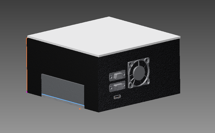

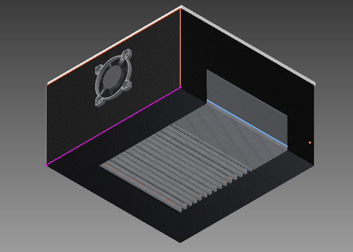
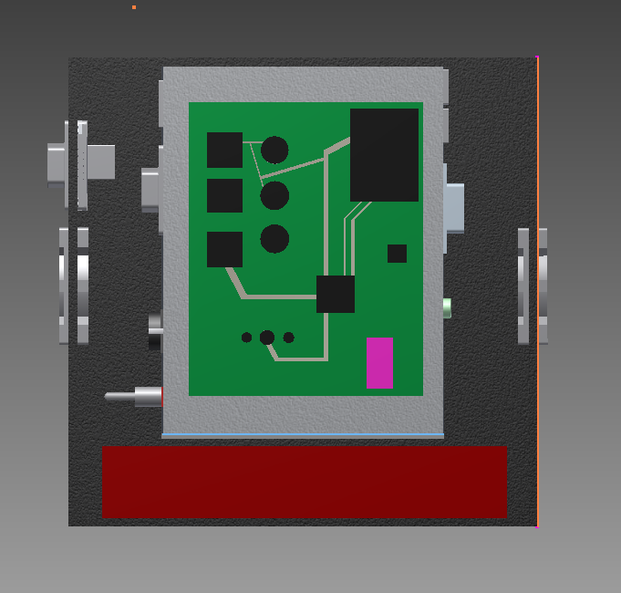
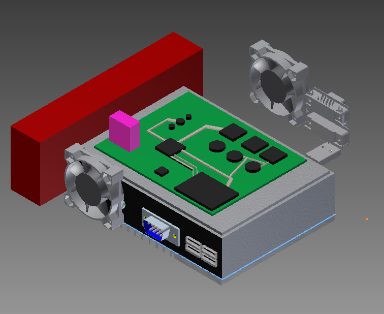
The final CAD drawing sheet can be seen here.
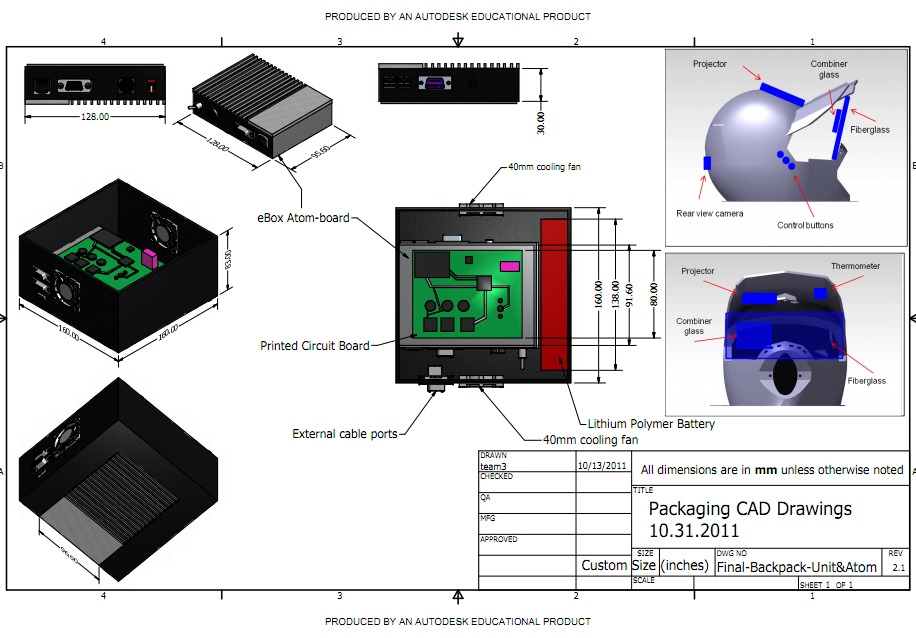
October 13th, 2011 (3 hours):
Finalized the details for the Design Review tomorrow. Printed out the handouts and a little extra for the course staff and peer reviewers. The documents that were supplied at the design
review are as follows: PCB, Schematic.pdf, and CAD Drawings.
October 16th, 2011 (3 hours):
Worked on the Voltage regulator circuit. The
through-hole switching regulator version was the adjustable LM2596, so some
configuration was required with resistors to get the desired 5V output.
After some circuit debugging, 5V output was acheived. The next objective was
to power the Atom with the circuit. The Li-Po battery was used to power the
switching regulator, and in turn the Atom board (the LiPo battery was used
sparingly for testing, as the battery management circuitry was not in place
yet). Suchessfully managed to power the Atom using the Li-Po battery and
through-hole LM2596-ADJ.
WEEK 08 SUMMARY
Accomplishments: Updated CAD drawings to latest
revision. Completed design review - great success. Prototyped power circuit and
successfully powered Atom board on battery power.
Weekly Work Total: 16.5 hours
Project Work Total: 129.5 hours
Week 09
October 17th, 2011 (3 hours):
Noticed an issue with the
power circuit, where the entire setup would power off after the Atom had been on
for about 10-40seconds. After much debugging, shortening of the wires used
proved effective in halting this problem.
Chuck was also gracious enough
to provide a breakout for the SMD version of the LM2596-5.0 (non-adjustable)
that will ultimately be used in the final PCB. This brought a whole new slew of
problems however. The LM2596-5.0 produces 5V, and powers LEDs, fans, etc, but as
soon as the Atom board is hooked up to it, the output drops to 2.8V, which is
obviously not enough for the Atom, which then refuses to power up. As soon as
the Atom is removed from the load part of the circuit, the output goes back up
to 5V. This is extremely strange to the team, and consultation with the Georges
may be necessary.
October 18th, 2011 (6 hours):
Discovered the problem with
the switching regulator circuit! It turns out the inductor is not a true 2-pin
device as the datasheet might imply. The 4 pins of the inductor were all
connected to the breadboard for prototyping purposes, and this was causing some
sort of feedback that was causing abnormally large ripples in the DC output.
Simply snipping the 2 extraneous leads off the inductor solved the problem. The
working switching regulator circuit was then used to successfully power the Atom
with a successful POST.
Now that the
circuit was working, a protoboard with the components was made to facilitate use and free up the breadboard for
prototyping the battery charging IC. The LM2596 switching regulator protoboard is pictured below.
Work commenced on protoyping the bq24005 battery charging IC. Several
attempts were made with Marcelo to get it to work. The IC put out IMMENSE
amounts of heat. So much heat that the flux began to vaporize. Not good.
The IC has two status LED outputs that can be used to verify operation and
current operating state. These LEDs initially flickered when the circuit was
powered on, but later remained off. After this, the circuit was left on for a
few minutes to 'charge' the battery. This is when the flux vaporization
happened, and after that the two status LEDs remained on no matter what was
done. Even more worrying - when the battery was hooked up again to test
charging, it seemed as though the battery was connected to the Vcc rail, when it
should be isolated. Puzzled, no further headway was made by the team.
Consultation with the Georges may be necessary.
October 19th, 2011 (8 hours):
After consultation with
the Georges, the conclusion was made that whatever internal circuitry was
isolated the input/output lines (Vcc and Battery) must have been damaged. It was
decided to try another IC and see if the same behavior was observed. The circuit
for this was set up but not debugged in detail in an bid to focus on the PCB
effort.
With regards to Chuck's suggestion during the design review - he
suggested we control the cooling fans with the microcontroller so we aren't
wasting too much power all of the time. The team worked together to quickly
design, test and implement the switching circuit (using a 500Ohm resistor and
2N3704) into the final design. The fans were successfully switched on using a
single GPIO pin on the microcontroller. The changes were incorporated into the
schematic and PCB immediately.
A significant portion of time was spent
reviewing CAM procedures for the PCB fabrication. It was finally learned that
Sparkfun provides their own CAM file which makes prep for fabrication easier.
A test CAM job was run, with the results being sent to FreeDFM to verify that no
show-stoppers were present. There were some difficulties with correct file
extensions, particularly the drill file. One job succeeded without any
show-stoppers, but the lack of certainty regarding the files/file extensions
uploaded rendered the results moot.
Nikhil also continued making some
last minutes tweaks and changes to the PCB layout, working towards finalizing
the layout.
After some more debugging, and with the help of Marcelo, a
new charging IC was tried - this time we also had Chuck drill a hole on the
bottom of the PCB as is recommended on the layout. After re-setting up the
circuit on a breadboard, the new IC was connected. In a dramatic turn of events
- nothing happened. After spending some time debugging, it was discovered that
the TSSOP-breakout board the IC was soldered to was slightly curved, and as a
result majority of the pins were not touching the pad. After re-soldering the
pins, it worked like a charm! The circuit functioned as expected, and the status
LEDs verified the functionality.
October 20th, 2011 (8 hours):
The final PCB revision
was completed by Nikhil, and the CAM job was run to generate the neccesary
Gerber files. The list of specific file extensions to be used, provided by
Chuck, helped clear up the issues with file extensions from the previous day.
The BOM and proof of parts were also completed. The final PCB can be seen below,
along with the proof of parts.
The final Gerber files can be found
here.
Using the charging IC, battery and switching regulator, it was attempted to
load the battery while charging it as well. The 'load' used was a simple red
LED, and the charging IC was connected to the battery. While charging and
loading was possible, it appears that it takes the battery much longer, and
results in 'trickle' charging the Li-Po pack. Due to the nature of our battery,
this is not recommended, as it could reduce the long-term performance of the
battery pack. The next step will be to power the Atom board for an extended
period of time using the battery pack, and experimenting with connecting the
charging IC at the same time.
Some time was also spent getting the
Charging IC circuit onto a protoboard to allow for more robust testing, as well
as to free up the breadboard.
WEEK 09 SUMMARY
Accomplishments: Sucessfully protoyped switching
regulator and battery charging circuits. Completed PCB design and submitted
Gerber files for fabrication. Began testing simultaneous loading and charging
capabilities of the circuit.
Weekly Work Total: 25 hours
Project Work Total: 154.5 hours
Week 10
October 24th, 2011 (4 hours)
Much of
the day was spent finalising the proto board for the battery charging circuit.
Some time was spent debugging the circuit - for some reason the LM7809 was
producing 4.5V instead of 9V. The cause of this was found to be a floating
ground wire on the LM7809. Once this was rectified, and the solder joints
cleaned up, the circuit was tested without the battery. The circuit successfully
powered up, and the status LEDs showed correct functioniong, as shown in the
pictures below.
October 25th, 2011 (6 hours)
The
battery charging circuit was tested with a battery load and functionality was
sucessfully verified. By watching the current draw on the benchtop power supply
used to power the charging circuit, the execution of the charging algorithm
could be seen.
After consulting with the resident Visual Studio and C#
expert, B. Bowman, the team came to the consensus that building the GUI for the
atom board should be done in VS and C#, due to its native support of the serial
protocol, and ability to interface easily with USB devices.
The
remainder of the evening was spent trying to get a sample program working with
the serial output of the microcontroller. Blaine reprogrammed the
microcontroller to output a simple series of number (0-9, looping) so that a
simple C# program could be devised to mirror the output of the serial port.
A simple application was written that opens the serial port, records the
bytes until a 0 is encountered, and the outputs the numbers to a listbox. After
much consternation in trying to intialize the serial port, it was discovered
that a mere two lines of code were needed to initialize the serial port.
// Code start
SerialPort port = new SerialPort(
"COM3", 38400,
Parity.None, 8, StopBits.One);
// Code End
October 26th, 2011 (6 hours)
After successfully demonstrating the serial functionality in C#, the next
step was to
interface the USB webcam with it. After searching on various
forums and code
project websites, the best solution found was a library
called
AvCapWPF, which is based on the avicap32.dll library. Unfortunately, the
libary had some niggles. The video feed was displayed upside down, and there
were no rotation properties that could be manipulated at a code level. Everytime
attempts were made to modify the code, it would break. After playing with it for
a bit, debugging and implementation was put off till tomorrow.
October 27th, 2011 (5 hours)
More time was spent trying to get the webcam libary to function correctly,
to no great avail. The problem of the upside down feature was temporarily fixed
by simply opening the control in expression blend, and rotating it like a normal
"object".
Even though the rotational issue was fixed, problems still
persisted. Attempting to import the control into a different application,
modifying the function calls for the library, and even adding elements caused
the application to break.
After some more attempts, the final state of
the sofware at the end of the evening was a stable, right-side-up video display.
October 28th, 2011 (4 hours)
Further consultation with the resident C# expert, B. Bowman, regarding the
unstable behavior of the webcam libary revealed that it was not the control
itself that was unstable. The cause of glitching was the 'preview' function of
the webcam feed - for some reason the preview feed hijacks the webcam feed,
preventing anything else from accessing it, including code that has been
compiled and debugged. Disabling the preview of the webcam resulted in much
better stability. A simple app in which a click button toggled the webcam
display on and off was written and compiled. This turns out to be better than
the initial approach, since the webcam is always 'on', just not shown, which
will allow switching between the webcam and telemetry data to be more fluid and
quick.
Marcelo mocked up a quick GUI with the various telemetry elements
and the webcam toggle, which can be seen below.
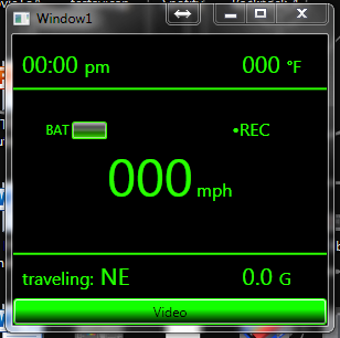
WEEK 10 SUMMARY
Accomplishments: Finished prototyping battery
charging circuit. Sucessfully interfaced with serial port and webcam using C#.
Weekly Work Total: 25 hours
Project Work Total: 179.5 hours
Week 11
October 31st, 2011
& Nov 1st, 2011
Had to have dental work done - was not in lab.
November 2nd, 2011
(3 hours)
Using Blaine's program on the Eval board which output packets
of 1s and 0s, attempts were made to get to a test GUI to 'live' update the
screen with data from the serial line. Implementation of a rudimentary polling
loop failed, upon which Blaine and resident C# expert B. Bowman suggested
implementing threading. Blaine attempted to implement threading, which was
unsuccessful. Some useful examples on serial implementation were found online.
Further implementation and debugging will be carried out next week.
November 3rd, 2011
(6 hours)
With Blaine initiating the PCB soldering efforts, the battery
charging circuit was the first to be tested. It exhbited some strange behavior,
whereby it's charging algorithm seemed to be turning off/on in a cyclical
fashion, but after letting it run through a partial charge cycle using the
battery pack, all behavior normalized.
While rooting around in the inner
sanctum of the senior design lab, a USB driven LCD monitor was discovered.
According to Chuck, its origins are unclear, but the team was given the go-ahead
to experiment with it. Initial experimentation was promising - the screen was of
a more manageable form-factor than the projector and its accompanying lenses
are. The screen also outputs significantly less heat than the projector, and is
more visible when viewed using the beam-splitter glass.
 |
|
|
After hacking away at the screen and removing excess packaging, as well as
hardwiring a USB cable to it for convenience, it was shown that the screen is
slim, light and generally better than the projector tech. While a little large
for the purpose, it will do. Smaller LCD screens were looked at, but initial
results were not promising.
Attempts to install Win Em 7 on the Atom
motherboard were made, to no avail. The compact flash card has a 'removeable'
flag set, preventing the OS installer from recognizing it as a OS install target
drive. It is proving extremely difficult to switch the flag from 'removeable' to
'fixed'. The card will be taken home and attempts to switch the flag will be
made on the home computer, which has a CF card reader.
November 4th, 2011
(4 hours)
After sucessfully demonstrating the 5V regulator function on the PCB, a
small hiccup was discovered with the 3.3V regulator. It was providing 4.3-4.5V,
and even after multiple devices were tested, no change was shown. It was
ultimately discovered that 2 config resistors are needed. Because of the nature
of the gain function of the regulator, the values needed were small - ~240 Ohm
and ~390 Ohm. This yielded a Vout of 3.28V which was deemed good enough for
government work.
Online research yielded a unique idea on the Win Em. 7
installation front - install Linux (which isn't as finnicky about
boot/removable/fixed disk flags) and then install Windows on top of that.
This will be executed tomorrow.
November 5th, 2011
(3.5 hours)
After attempting to change the CF card flags using Gparted
(off a Ubuntu liveCD), an WE7 install attempt was made again, to no avail.
Several flag/partition configuration attempts were made, and WE7 did not
recognize any of them.
In an effort to get SOMETHING installed on the
Atom box, an Ubuntu install attempt was made, which failed due to graphics
driver incompatibility. After some googling, this was discovered to be a fairly
common occurence with Ubuntu 11.04 and lower spec hardware, so attempts will be
made to try a different Linux distro.
As a backup plan, the 2.5"
harddrive on the dev netbook may have to be harvested for the Atom motherboard.
WEEK 11 SUMMARY
Accomplishments: Began initial PCB population with
Blaine, sorted out power issues. Major revamp of display tech occured, and CF
cards refuse to makeboot.
Weekly Work Total: 16.5 hours
Project Work Total: 196 hours
Week 12
November 7th, 2011 (6 hours)
Made further attempts to install
windows on to the atom box. Chuck provided a SATA cable and PC power supply
which were used to power the harddrive and connect it to the atom box. The idea
was that Windows 7 could be installed on the harddrive, and then a utility run
to convert the compact flash to a bootable fixed disk. However, after 3
attempts, windows failed to install on the harddrive.
Work was also
started on preparing the helmet for the rearview webcam. Unfortunately it was
also discovered that there's over two inches of foam between the inner part of
the helmet and the shell that needs to be removed. Luckily a dremel tool was
purchased over the weekend which greatly sped up the process.
While
attempting to install the webcam, the adjustable focus began to act up - every
time the webcam was placed inside the helmet, the focus would change due to the
motion. Also, a small piece of glass was discovered on the CMOS sensor, which
was obscuring the image partially. Attempts to remove this piece of glass
resulted in breakage of the glass, ruining the webcam image. Work was halted for
the day, while a new webcam was purchased. The new webcam purchased was the
Microsoft VX - 800.

A cardboard mockup of the visor was also made, and traced out onto
plexiglass, which was then given to Chuck to cut out.
November 8th, 2011 (6 hours)
Continued installing the webcam, with
great success.
The picture above shows the webcam niche just before the final excision and
placement.
The plexiglass pieces submitted for cutting yesterday
arrived, and while in the process of mounting it to the helmet, Marcelo pointed
out that the screen is not likely to fit with the current plexiglass design.
This was a major flaw in my design. After further thought, and consultation with
Chuck, it was decided to radically overhaul the plexiglass visor design and
screen mounting solution. A mockup was made using cardboard. The second mockup
was designed, with many more straight edges for ease of fabrication. The final
mockup, along with the combiner glass was tested, and is pictured below.
Also, Windows 7 finally installed! The reason is not immediately clear why
it worked today and not yesterday, but it is suspected that the changes made in
the BIOS yesterday were somehow not recognized till today.
Now that windows 7 is on the harddrive, the next step is to get windows onto
the compact flash card.
The structure of the helmet was also modified to better acommodate the new
visor design.
November 9th, 2011 (2 hours)
The cardboard mockup of the new
helmet visor design was transferred to the plexiglass sheet and submitted to
Chuck for routing.
Further attempts were made to prime the CF card for
installing an OS, but attempts failed again. For now, alteast Win Emb 7 is
running stable on the Atom.
November 10th, 2011 (4 hours)
With Marcelo's help,
holes were drilled into the helmet for mounting the side plates. Due to the use
of foam as padding for the helmet, mounting any hardware inside is proving
challenging. Superglue is out of the question as it dissolves the foam and
provides no grip. For now, stuffing metal standoffs into the foam, with a screw
as an anchor has proved effective. For future endeavors, perhaps self-drilling
drywall anchors may be more useful. The top visor was also screwed in.
November 11th, 2011 (2 hours)
Began designing and
constructing a mount for the actual USB LCD screen that will go in the helmet.
Soldered LEDs onto the PCB for Blaine to use as diagnostic/heartbeat indicators.
After some kerfuffle with programming the micro, Blaine successfully
wrote to the microcontroller - but the UART was misbehaving. Debugging to
follow.
November 13th, 2011 (5 hours)
Met with Blaine to debug
the UART issues. It appears that the micro is outputting serial data correctly,
but the MAX 3232 line level translator was malfunctioning. Analysis of the
schematic revealed that two polarized caps were placed incorrectly which was
part of the problem. Fixing this did not solve the issue, until Blaine noticed
that the TX/RX of the micro were connected incorrectly to the TX/RX of the
MAX3232. After some fine flywiring, great success followed!
The helmet
display unit was finally completed! After a lot of plexiglass bending,
hole-drilling and brace-building, the results are shown below.
Furthermore, since the UART was working, the GPS, some more
headers, and a few other miscellaneous components were soldered on.
WEEK 12 SUMMARY
Accomplishments: Finally installed something to
Atom Board. PCB population chugging along. Helmet construction (webcam, display
and visor mounting) complete, weatherproofing will come later.
Weekly Work Total: 25 hours
Project Work Total: 221 hours
Week 13
November 14th, 2011 (5 hours)
Work was done to put the
finishing touches on the helmet. Save for some silicone weatherproofing and the
control buttons, the helmet unit is complete.
A new issue with the window 7 embedded also surfaced - it refuses to
install any 3rd party drivers. After some research, it was decided that windows
7 starter would be a much better option, and with some help from B. Bowman, an
image for Win 7 Starter will be obtained.
Work was done with the GUI,
where the entire Serial port interface was re-written to use thread invoking to
handle the SerialPort Data Received events, on the advice of resident C# expert,
B. Bowman. There were some still issues where the thread would hang after a
random period of time. The exact cause of this was not known, and further
investigation is planned for tomorrow.
November 15th, 2011 (4 hours)
Brought Marcelo up to
speed regarding the latest HUD mounting hardware, and the new GUI code. Changes
were made to the GUI to accomadate the newest HUD changes, namely the new
portrait orientation of the display, as shown below. Refer to Marcelo's notebook
regarding the exact details of the test code implemented.

November 16th, 2011 (3 hours)
The GUI code continued to
be buggy, quitting randomly after display an exception. It was thought that the
USB->RS232 adapter being used might be affecting the serial port code in some
way, so the GUI was hooked up to the lab computer which had a real COM port. The
GUI seemed to function better, but it still hung after some time. It is not sure
if the Serial port code itself is malfunctioning, or it is the rapid switching
between webcam visible/not visible that is causing the hanging.
November 17th, 2011 (4 hours)
Met with Blaine and
Marcelo to discuss the finer points of the data packets being sent between the
Atom and Microcontroller. Blaine has devised a 5 character lead 'word' for each
specific packet. Marcelo notes that it will be trivial to get the Atom gui to
process these packets due to the extensive string parsing libraries in Visual
Basic. Because it is expected to be easy to parse the packets, more time was
spent on trying to figure out why the Atom GUI was so unreliable.
Also
worked with Marcelo to add buttons to the helmet. The historic color combination
of RGB was chosen. The buttons were also ergonomically positioned to be within
easy reach when operating a motor vehicle or some other activity.
A major issue was also noticed with the Windows Embedded 7 being used
currently - there is virtually no driver support. The webcam, USB display and
peripherals refuse to install drivers allowing them to be used properly. The
only drivers that installed correctly were generic HID drivers for the keyboard
and mouse.
November 18th, 2011 (4 hours)
With the help of B.
Bownman, a Windows 7 Starter image was obtained and installed to alleviate the
driver issues. Unfortunately, a large number of updates were required before
anything useful could be done, which took a long time to complete. There was
also significant effort required to get the USB screen to run - there seemed to
be a lot of conflict between the native VGA drivers and the DisplayLink drivers
for the USB screen. After much consternation, great success!

November 20th, 2011 (4 hours)
Met with Marcelo to test
the USB screen with the webcam and GUI on the Atom Board. The AtomGUI refused to
cooperate with the USB screen and webcam combination. The GUI would either
crash, freeze or open with multiple instances and then crash.
The webcam
would start but not display, when tried in a separate webcam debugging
application. This was rather strange, because the components all worked
individually, but when combined, everything went awry.
All updates,
drivers and software were in place, and the board itself should have had plenty
of power to handle the GUI and webcam processes. It was noticed that the webcam
worked when using a VGA display instead of the USB display, so in a last ditch
effort, the PicoProjector was connected to the atom board, and lo-behold,
everything worked!
The webcam/HUD switching still caused it to crash
after a while, but it was FAR more stable than anything seen so far. It may just
be the webcam/serial rapid switching that is causing the freeze.
Worked
more with Marcelo to re-re-do the display packaging. After throwing around a few
ideas, it was decided to model the new setup after rear projection TVs, with the
projector projecting the image through the top of the helmet onto a substrate
below for image formation. Work was done on the helmet to make room for the new
display method while gutting the old. Preliminary tests showed promise, though
experimentation will have to be carried out to determine the final alignment and
best substrate.
Tinting of the plexiglass visor pieces was also
attempted, as they are looking quite scuffed and scratched up. Unfortunately,
the poor condition and lack of professional tinting skills and tools made this
difficult. It was decided to look for some sort of spray paint-type clear coat
tint.
WEEK 13 SUMMARY
Accomplishments: Lots of major milestones this
week! GUI was developed to near completion - only file logging functionality
remains. While the USB screen was working, it was decided that the projector is
a FAR better option, so the team returned to that as the display tech. The
helmet packaging also saw significant steps as far as the buttons and display
mount hardware was concerened.
Weekly Work Total: 24 hours
Project Work Total: 245 hours
Week 14
November 21, 2011 (4 hours):
Met in lab to attend the
Cornell Cup Webinar. Basically a general QnA session for participants.
Worked a little bit with Marcelo to get the packet parsing going, but after he
completed the bulk of the parsing, great sucess! The GUI updates smoothly,
though in the lab only the temperature and accelerometer work because the GPS
unit has no line of sight with the sky.
Significant thought was given to
how the projector should now be mounted. It was decided to continue this effort
tomorrow, after obtaining some hardware from Walmart.
November 22, 2011 (4 hours)
Worked on getting the
projector mounted. Using some L-brackets bent into shape, the projector was
finally mounted - this was a much more arduous task than originally anticipated,
mostly because it took a lot of time getting the angle of incidence just right,
as well as balancing the weight of the projector along the medial axis of the
helmet. A lot of time was spent trying to mount it without destroying or gluing
any part of the actual projector. Finally it was decided to use the VGA adapter
the projector originally came with.
November 25th, 2011 (3 hours)
Obtained some fresh
acrylic and tint for the visor. With the help of Beering Enterprises, the new
visor pieces were fabricated and finished. With the use of an awesome tinting
kit from Lowes, the visor pieces were tinted in no time, and look fairly
professional.
<image placeholder>
WEEK 14 SUMMARY
Accomplishments: Attached the new projector mount
and made new tinted visor pieces.
Weekly Work Total: 9 hours
Project Work Total: 254 hours
Week 15 - The Home Stretch
November 28, 2011 (3.5 hours)
Installed the newly
fabricated and tinted visors. The projector mount was also better aligned with
the image projection substrate (a piece of frosted plexiglass) to allow the
whole image to show. Acrlyic side panels for the backpack unit were laid out on
a large piece of acrylic and submitted to Chuck for fabrication.
The
industrial compact flash card was ordered through Chuck as well. It is hoped
that this will solve the problems of installing the OS on solid-state flash
storage that plagued the team earlier.
For current development purposes,
a harddrive is being used. So, as a contingency plan, a harness was fabricated
for the harddrive so that it can be used in the backpack unit should the second
compact flash card also fail.
<image placeholder>
November 29, 2011 (3.5 hours)
The Atom board which was
in a state of disassembly for development purposes, was put back together.
Working with Blaine, the most appropriate layout for the Atom, PCB, battery and
fans was explored on the backpack unit base-board.
As options were
explored, Chuck showed up with the cut out pieces for the rest of the backpack
unit. Some time was spent aligning and drilling the appropriate holes and
assembling the backpack unit.
<image placeholder>
Work was done
on the helmet in an attempt to seal it and align the visor pieces with each
other and the helmet. Proposed adhesive solutions were not as effective as
hoped, leading the team to resort to Loctite superglue.
A major problem
was also discovered with the Atom GUI. While the GUI works well enough on the
lab development computer, it continally crashes on the Atom board. The reasons
for this are not immediately clear, and must be investigated further.
November 30th, 2011 (4.5 hours)
The day's efforts were
primarly concerned with fixing the Atom GUI. Working with Marcelo, we managed to
get GUI to a slightly more stable state, but it still crashes randomly.
After tweaking it over and over, the cause of the failure is not known. It is
suspected that the large amount of 3rd party code used for the webcam view is
causing some sort of problem. A new GUI was created, with all 3rd party code
removed, and only team-generated code.
Right out of the gate with the
new code, it ran for over an hour and a half without crashing. The code still
crashes randomly, but is stable for several hours before it does so. Further
investigation is needed.
The GUI was left running over night to test
robustness.
December (!) 1st, 2011 (4 hours)
The GUI from last night
crashed, but on restart, it ran for around 3 hours.
The industrial
compact flash card arrived! Before the mocked-up backpack unit was torn down,
worked with Blaine to take the unit outside in a bid to test a few PSSCs. The
entire system functioned well on battery power, drawing almost 2.5A at peak -
good for over 2 hours of battery life. The main motivation behind taking it
outside, though, was confirming the GPS unit was able to get a fix in the
system. The bearing function was sucessfully demonstrated (though the bearing
calculations were slightly off). A few of the GPS parameters were parsed
incorrectly, which is easy enough to fix. Overall a great sucesss!
The
next step was to take the Atom out and install the industrial compact flash
card. Before doing this, a quick field debugging station was put together so
that Blaine could take the PCB outside and tweak the GPS unit, and polish the
serial output from PCB.
Windows 7 starter installed sucessfully on the
compact flash card. It was also discovered that if the battery was taken out of
the projector, the current draw dropped by almost 1A, effectively giving us 3.5
hours of battery life now.
Marcelo brought in some more mounting
hardware for the backpack unit - and began implementing the idea of having a
hinge on the large panel on the backpack unit for easy debugging access. Some
excellent green spray paint was also purchased for the helmet - working with
Blaine it was determined that it would work well with the surface of our helmet.
Regarding the stability of the GUI - Blaine came up with an Autohotkey
script that would detect a program crash and restart the GUI if needed.
December 2nd, 2011 (4 hours)
Objective of the day was to
have the helmet completely painted. Spent some time attempting to get lettering
stencils cut out for the helmet using masking tape. This endeavous proved
fruitless and frustrating. It would be much easier to get mailing labels and cut
those into shape. For version 2, perhaps.
Thanks to the kindness of Dave
Azpell in the 402 shop upstairs, use of the fume hood and paint cabinet was
acquired. The visor was painted without much fuss, and the final result are
shown below.
The next step was to paint the helmet. After sufficiently masking it off to
protect the lining and internal components, it was primed as shown below.
Unfortunately, the brace supporting the helmet while being primed gave way,
and the helmet fell on the wet primer against the paint cabinet leaving a nasty
scar. The remainder of the time was spent rectifying this snafu, leaving the
final painting for tomorrow.
December 3rd, 2011 (2.5 hours)
Paintwork on the helmet
resumed. The primer on the helmet had dried and cured enough to be sanded down
to reduced the scarring caused by yesterday's error. Unfortunately the area can
still be seen, but it is not as bas as when it first happened. The drying helmet
can be seen below.
The completed helmet can be seen below as well. Unfortunately, the paint
chips quite easily, so some form of clear coat paint needs to be applied.
<image placeholder>
December 4th, 2011 (6 hours)
Worked on the final team poster and senior
design report. The power switch on the atom was relocated and extended to allow
for placement off-board. Additionally, a silicone sealing-ring was laid out on
the backpack unit to help with dust and water resistance.
Some issues
with the GUI were rectified, and Marcelo completed the data logging file
generation code. There was a serious glitch with the code however, but Blaine
discovered it was merely a case of improper file name generation that was
causing an exception to be thrown.
The backpack unit was also wired up
with all the necessary power connections, and laid out again.
Touchwood,
at this point, all PSSCs seem to be ready for atleast intial demonstration.
- display change is working
- telemetry data is functional
- battery
management is functional
- file writes are functional
- the HUD is up and
running using projector technology.
WEEK 15 SUMMARY
Accomplishments: Redid the GUI code to exclude
webcam functionality which will have to implemented in some other fashion. Data
logging was mostly completed. Helmet was painted.
Weekly Work Total: 28 hours
Project Work Total: 282 hours
Week 16
December 5th, 2011 (4 hours)
Met with Blaine in lab
to finish packaging the helmet and backpack unit.
Demonstrated 3/5 PSSCS (initial demo) to G. Toh. Unfortunately our battery
charging IC seems to keep shutting down periodically. Reasons for this are
unknown, but luckily we have a back-up wall charger unit that G. Hadley
suggested we use (at the beginning of the semester - so always listen to G.
Hadley)
The GUI code
was also modified to output .kml files instead of .txt files. The GUI was also
generating data points ~15 times a second and storing it to file. This is
redundant as the GPS data only gets updated once a second, so the updating loop
was fixed to generate data points only if GPS data was updated.
Some
issues were also noticed with the battery bar in the GUI and how it was not
updating. Attempts were made to fix it to no avail, so further investigation is
needed.
December 6th, 2011 (8 hours)
Spent some more time
trying to debug the GUI and determine why the battery bar was not updating.
Debugging showed that the battery update conditional statement wasn't even being
entered, which was odd considering PuTTy showed that all the parsed output was
normal, and the other input parsed by the GUI was working normally. Finally
Blaine had the idea to use the visual studio 'output' window to see what the GUI
really 'saw' on the serial line. It turned out that visual studio itself was
reading input from the serial line compleetely wrongly. There were random new
lines, missed carriage returns, and truncation of random strings. It was
initially thought there was some sort of timing issue between the
microcontroller and Atom serial interface, so several 'waits' were introduced
into the microcontroller code by Blaine. The issues still persisted. The next
possibility was with the buffer size on the GUI side, so the buffer size was
quadrupled. This seemed to improve the stability of the serial line a little
bit, but issues still persisted.
Blaine finally discovered some strange
function call inserted into the code upon the suggestion of resident C# guru B.
Bowman. It caused Brian's code to resolve issues he was having with the
serial line, but at the same time seemed to be causing problems with the team's
code. Upon removal of the faulty function call, all issues were resolved.
A new problem surfaced, however. The battery charging IC began to fail
intermittently - it would charge for a few minutes, and then 'die' - but it
would return to life when power cycled, for a few more minutes. After much
consternation, it was abandoned, and the wall charger suggested by G. Hadley was
used. (Always listen to G. Hadley).
Once the battery was charged and
system primed, Marcelo was outfitted with the system for testing. Testing was
conducted on the Engineering Mall, and by Northwestern Avenue. The GPS signal
takes anywhere from 30second-5 minutes to acheieve a lock, but other than that
the system performs flawlessly. The data logged during testing can be seen
below.
December 7th, 2011 (6 hours)
Great success! All PSSCs were demoed
and signed off on. The quick demo video created is embedded below, and was met
with success in the PSSC demo session in FRNY, after which the team was invited
to present at ECE 270 and ECE 362.
Work on the documentation continued.
Additionally, the Atom boards for the cornell cup arrived! Some time was
spent playing with them - and they conveniently have a Linux distro already
installed!
Quick Demo
Video
December 8th, 2011 (8 hours)
Most of the day was spent recording video for the demos tomorrow and the final presentation next week. We
rode the bus and took a car ride with the device, logging lots of data and
garnering many strange looks in the process. The device turned out the be quite
reliable - it did not crash even once during use, and it lasted just under two
hours of continuous use on the battery.
The latter part of the day was
spent creating the demo video for the 270 and 362 presentations, incoporating
the new footage and data logged.
December 9th, 2011 (4 hours)
Seeing as all the newly logged data
was forgotten in lab the previous night, I had to come in and quickly
incorporate the newly logged data and finish the video before the 362
presentation. Great success was acheived. However, due to the unlicensed music
choices, the video was promptly banned from Youtube. The video was then uploaded
to Vimeo which is more accomodating of project videos. The final video is
embedded below.
WEEK 16 SUMMARY
Accomplishments: The Incredible HUD was completed
and all PSSCs were successfully demonstrated!
Weekly Work Total: 30 hours
Project Work Total: 312 hours
|


 The rest of the day was spent making the schematic and PCB footprint for the PIC32 QFP-100 package in Eagle. The PCB footprint proved particularly challenging
because of the custom pad sizes and extremely small pin spacing. It took several attempts to get the pin spacing just right, as some of the measurements on the PIC32
datasheet weren't very clear.

 Preliminary work was also started on the schematic and footprint for the voltage regulator package (LM2592).


