David Collins's Lab Notebook
Week 01
January 9, 2008 (2 hour):
Met with team to come up with project idea. The best idea at the time is a home electricity monitoring and cut off network using X10 power line communication hardware.
January 10, 2008 (2 hours):
Met with Matt and professors to come up with a project idea. The best idea formed was that of a UAV. After manual takeoff, the plane would autonomously fly to coordinates using GPS and take photos with a digital camera.
January 10, 2008 (3 hours):
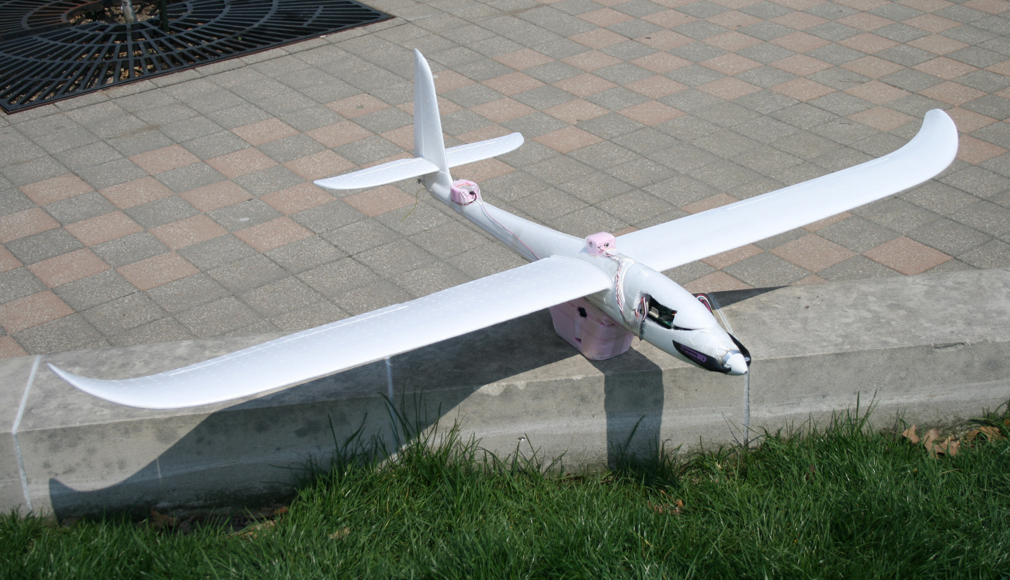
Investigated potential R/C planes as well as modding efforts to add cargo to planes. Found that a Multiplex EasyStar is the plane with the best chance of working for our team. It is made out of foam so it is capable of crashing without damage. This particular plane has been used for cheap aerial photography. Wrote and submitted the initial project proposal after conferring with teammates.
WEEK 01 SUMMARY
Accomplishments: Determined a hopefully solid project idea and another backup plan then submitted both in the initial project proposal. Made sure that the UAV project is at least feasible for a senior design project in both difficulty and cost.
Weekly Work Total: 7 hours
Project Work Total: 7 hours
Week 02
January 16, 2008 (3 hours):
Collaborated with team to write project specific success criteria as well as the majority of the final proposal. Investigated component choices in preparation for the design constraints homework.
January 17, 2008 (1 hour):
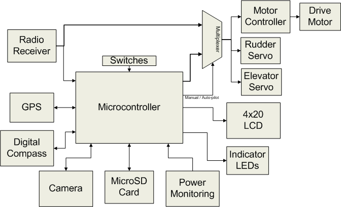
Created the initial block diagram to go into homework 2 while considering all of the devices that the project would be interfacing to. It would be best to choose a microcontroller with many more input pins that are initially required in case new functionality has to be added, as well as for fault tolerance.
Initial Block Diagram
January 18, 2008 (1 hour):
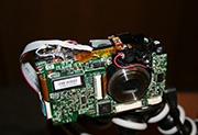
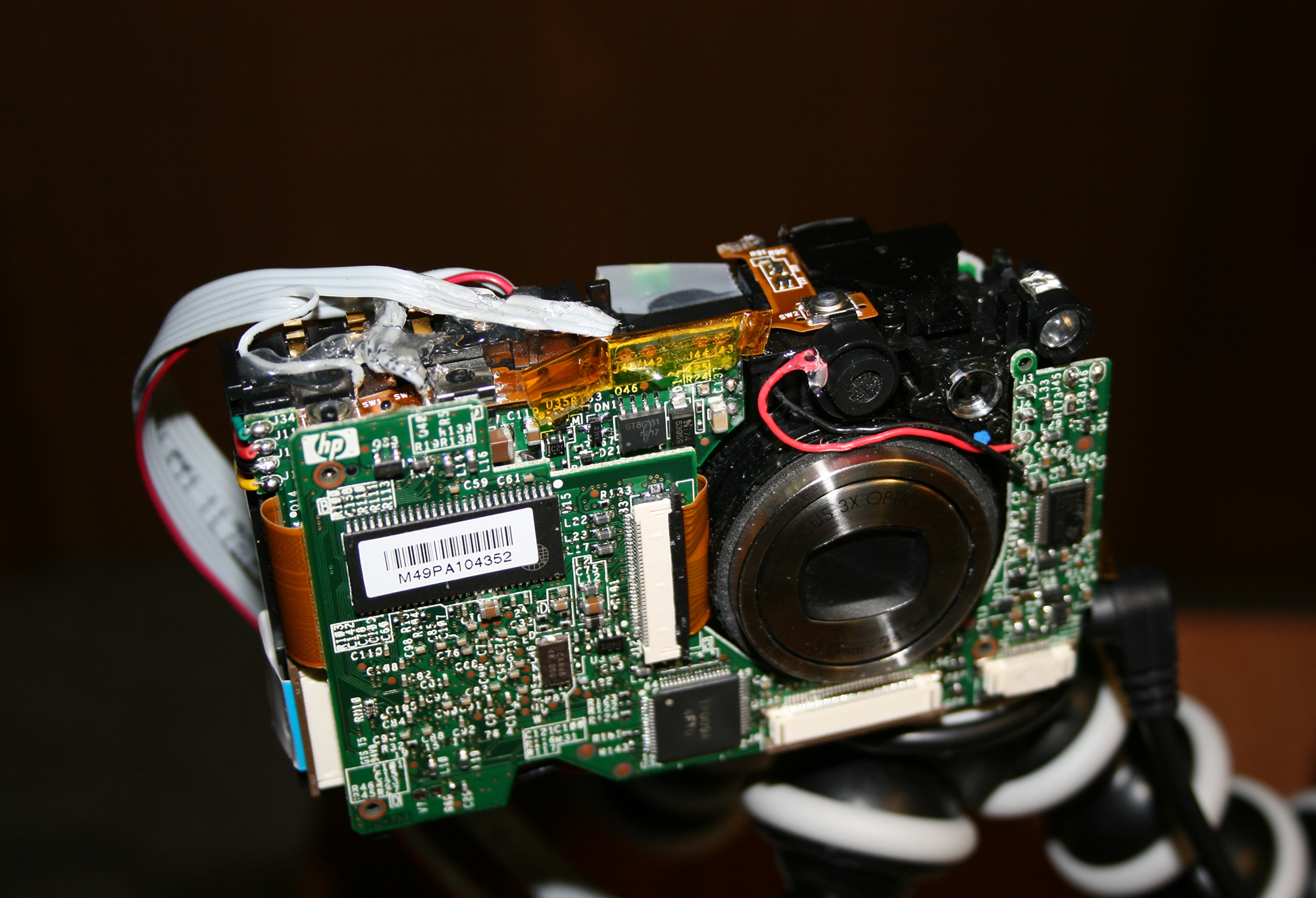
Took apart an HP Photosmart R707 digital camera in an effort to reduce weight and expose the control circuitry. This camera was donated because it has a cracked LCD screen. However, even with the external case removed, the camera weighs 5.2 oz. This may be too heavy for use in the UAV, but will be considered until a better substitute is found. If the camera battery is removed as well, another 1 oz is shaved off of the weight, but this would reduce flying time even further as the main battery would be needed to power the camera.
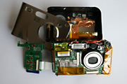
HP Photosmart R707
WEEK 02 SUMMARY
Accomplishments: Completed the final project proposal including a good set of project specific success criteria. Tinkered with a point and shoot digital camera in order to decide if it is useful to the project.
Weekly Work Total: 5 hours
Project Work Total: 12 hours
Week 03
January 22, 2008 (3 hours):
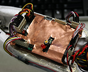
Continued the disassembly of the R707. Removed the flash capacitors and flash bulb. This brought the running weight down to 4.7 oz. Removing the flash unit also decreases the overall power consumption of the camera. There was some concern that the flash charging unit would fail after removing the capacitive load, but it appears to still function correctly. The camera will still take photos.
January 23, 2008 (4 hours):
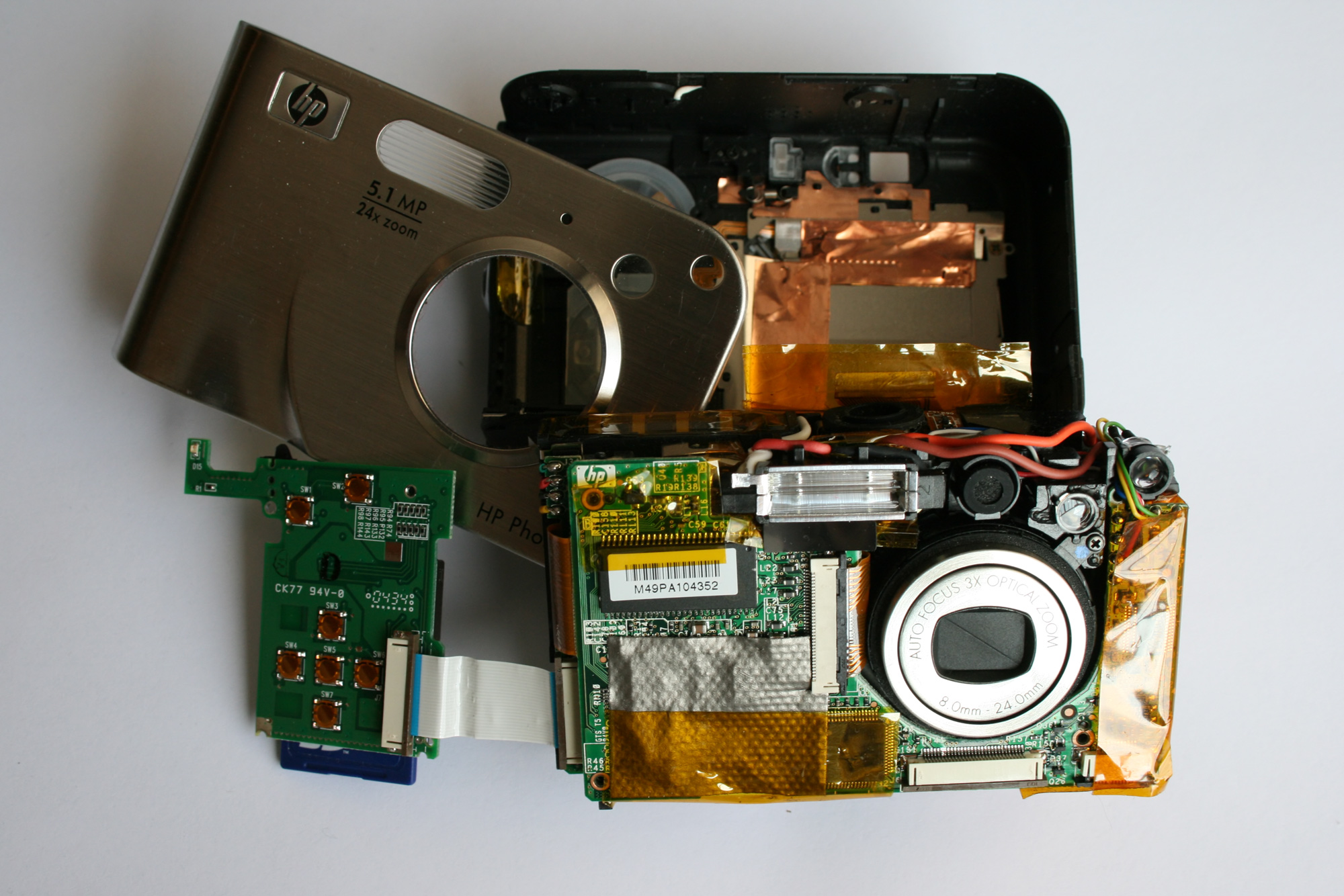
Investigated the circuit design of the push buttons on the R707. The on/off, shutter, and auto focus buttons proved to just be contact closures to ground. I was unable to figure out how the video button is wired. The zoom buttons also proved a mystery as both terminals register at 5 Mohm to ground and measure 2.9 V during operation. Another curious observation is how the ground on the switches compares to the battery ground. If the battery has been removed from the camera for awhile, the switch ground appears to have a resistance of 19.88 kohm to battery ground. However, if the battery was recently removed, the resistance shows up as 0 ohm.
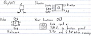
R707 pushbutton pin outs
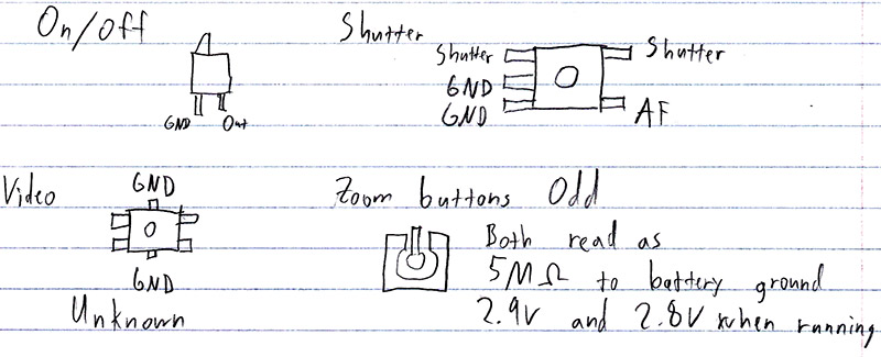
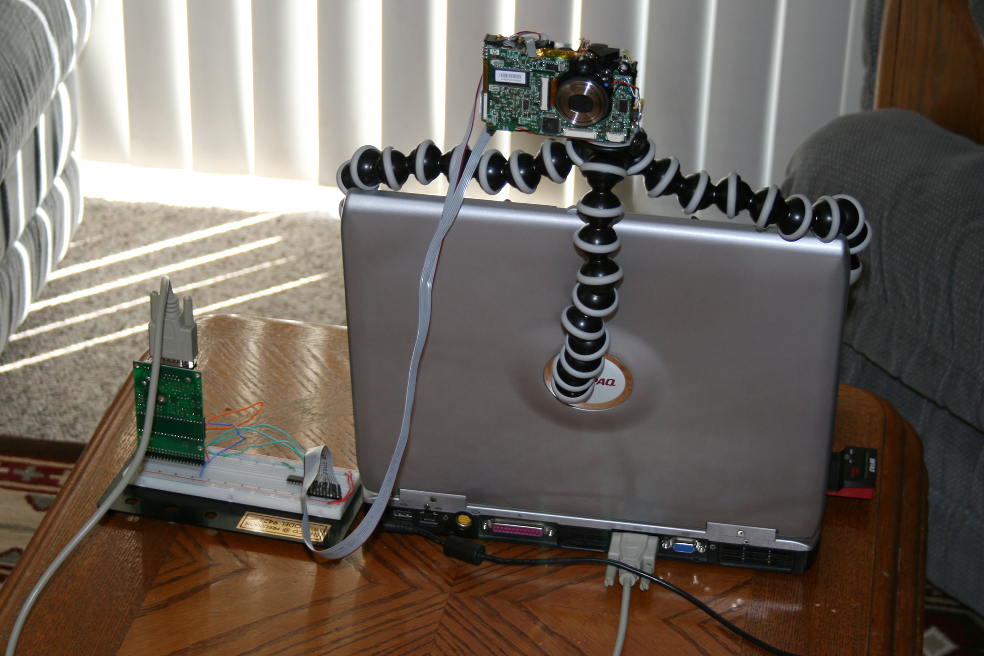
After determining the pin out of the pushbuttons, I soldered wires to all of the useful contacts I found. Here is the testing dongle pin out. I then removed the 9S12 microcontroller from my ECE 362 project and connected it to the R707 with a darlington array IC on a bread board. I wrote a quick program so that UART commands from a PC would translate into camera actions. This proved to be a good proof of concept for PSSC #4. I mounted the R707 on my gorillapod so that I could easily take pictures with it.
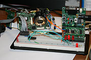
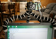
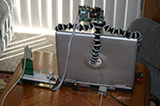
R707 testing setup
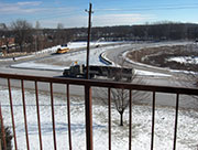

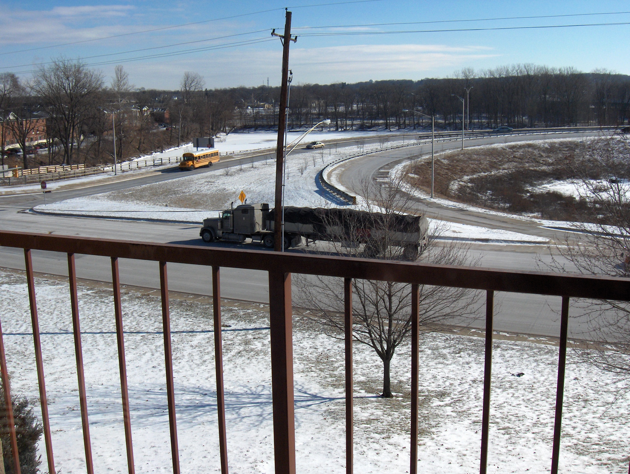
Photos taken with the R707 in the testing setup
January 24, 2008 (1 hour):
Researched the protocol used to communicate with SD cards. I found out that microSD cards can communicate over SPI just as normal SD cards do. I want to begin interfacing to SD as soon as possible so I searched the internet for parts to buy. I ended up buying a Kingston 1GB microSD card SDC/1GBKR from newegg.com for $10.98. I also purchased 3 microSD push-push connectors (656-ST2S008V1AR1500) and 3 3.3 V LDO voltage regulators (511-LD1084V33) from mouser.com for a total of $16.90. I will be able to begin writing a driver for the SD interface once these parts arrive.
January 27, 2008 (3 hours):
Talked with Matt online to determine which microcontrollers would be best suited for our project. We are mainly considering microcontrollers in the 9S12 family because they easily fulfill our I/O requirements and we all have experience working with them. I ended up ordering free samples of the following microcontrollers from Freescale: 4 MC9S12NE64CPVE, 2 MC9S12XA512CAG, 2 MC9S12XA512CAL, 2 MC9S12A64CFUE, 2 MC9S12A512CPVE
I talked with a friend I met on an internship two years ago. He has extensive experience with all things related to R/C airplanes and will look over our bill of materials. He suggested against buying the ready-to-fly kit. Instead, we should purchase the basic plane kit, a brushless motor, a motor controller for it, Li-polymer batteries, a charger for them, and a 4 channel radio transmitter/receiver pair. This will all undoubtedly be more expensive than an RTF kit, but it will have all of the power and range we need. Also, the 4th channel on the radio will be used for the manual to auto-pilot switch. This leads to a much more intuitive interface instead of some control toggling sequence.
WEEK 03 SUMMARY
Accomplishments: Determined the pin-out of a candidate digital camera and successfully interfaced it to a microcontroller. Began seriously looking into peripheral selection.
Weekly Work Total: 11 hours
Project Work Total: 23 hours
Week 04
January 28, 2008 (2 hours):
Looked through the technical documents of various parts online to determine how many I/O pins the microcontroller needs to have. One thing I noticed is that the Hitachi HM55B Compass Module does not use a standard interface. This is both a good and bad thing. On one hand, it reduces the port requirements for the microcontroller. On the other hand, it means that a bit banging driver has to be written to communicate with the compass module. Other compass modules exist which communicate over I2C; however, they are physically larger, and substantially more expensive. The HM55B is probably more appropriate for the project. I made a Google Docs spreadsheet illustrating the I/O requirements for the microcontroller. This will hopefully help Matt in the writing of homework 3.
January 29, 2008 (3 hours):
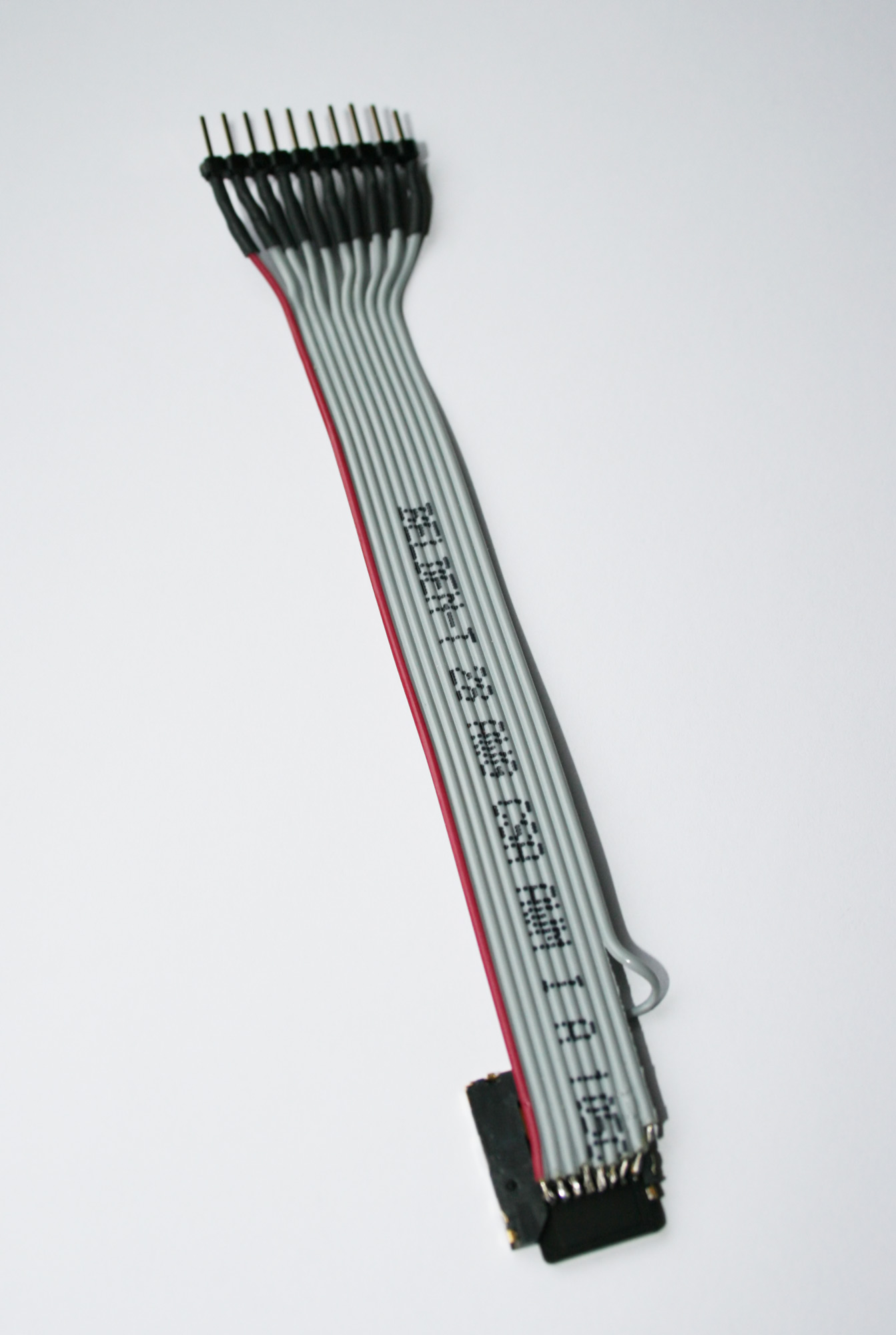
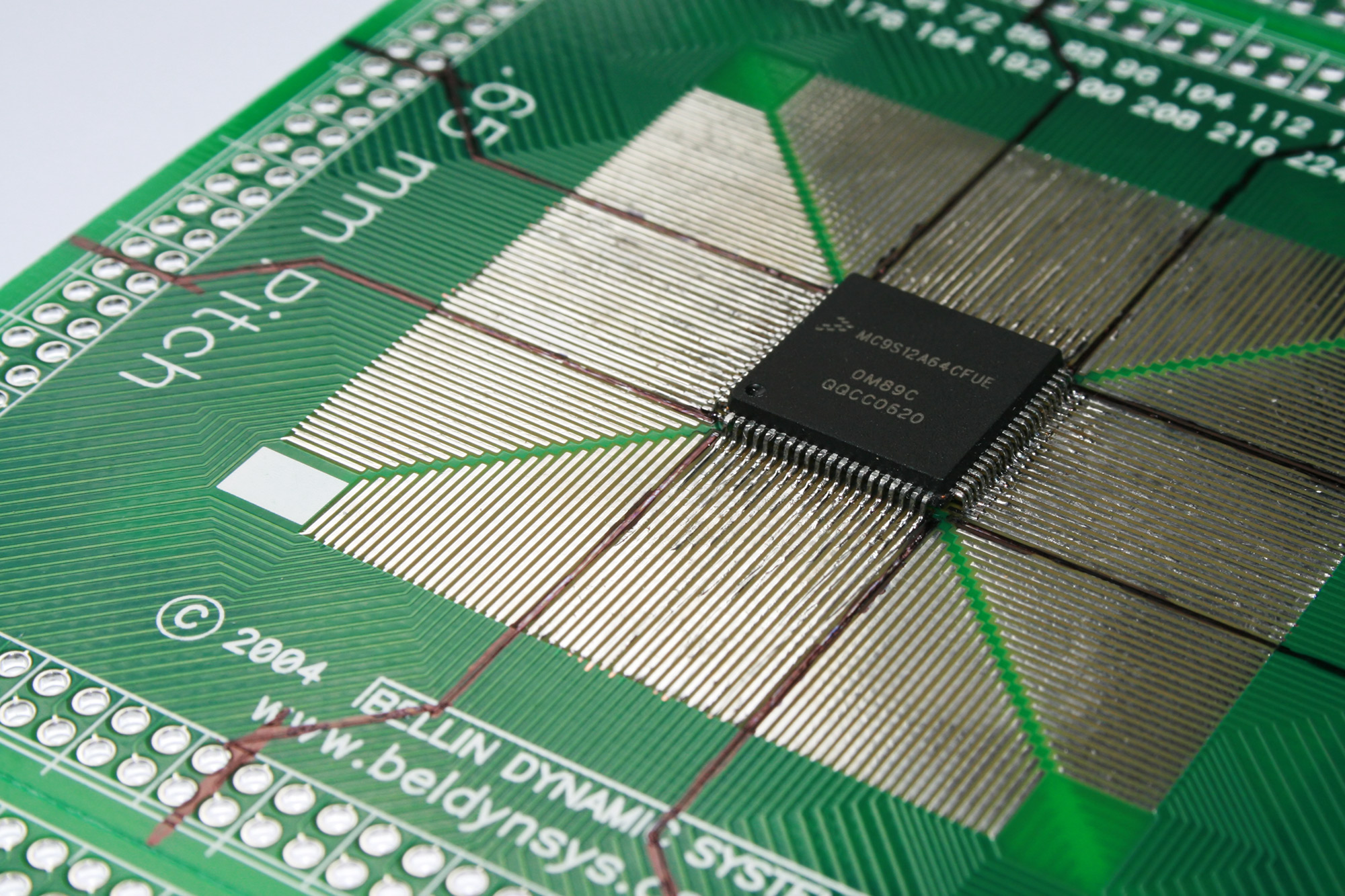
Conferred with team to decide upon a microcontroller to use in the project. We decided to use the 80pin MC9S12A64CFUE. It has more than enough I/O for our needs and is smaller than its 112pin cousin. We also discussed R/C plane parts. I went into the lab to solder a ribbon cable onto the microSD connector I ordered. I will begin writing a driver on the 9S12C32 when the card arrives tomorrow.
January 30, 2008 (4 hours):
Extensively researched the SPI mode of SD cards in both technical documents as well as example source code. Through this research, I found that all of the pins on the microSD card must be pulled high with a 50-100kOhm resistor. This meant that I had to resolder the dongle I made yesterday because I had left the NC pins unconnected. I ended up wiring the card insertion switch as well.. Here is the SD card testing dongle pin out.
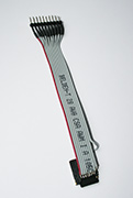
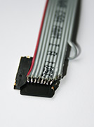
microSD Card Testing Dongle
Here is a list of the websites that are useful for SD card interfacing:
FlashGenie SD card interfacing and 9S12 example code
Explanation of the CSD register and how to calculate card capacity
Physical interfacing and most important commands
Tiny-Fat library to implement FAT16
MicroSD card pinout
January 31, 2008 (10 hours):
Built a prototype circuit to connect the microSD card to the 9S12 microcontroller. The main consideration is that the microcontroller operates at 5 V and the SD card needs 3.3 V. I spent a lot of time researching which IC would work for the translation. Two ICs seemed to be perfect for the task: SN74LVC2T45 - Dual-Bit Dual Supply Transceiver, SN74LVC8T245 - 8-Bit Dual-Supply Bus Transceiver. Either of these would work well for the project as they can operate up to 300MHz. Unfortunately, these are only produced in surface mount packages and the even then, the ECE store room did not have any on hand. Instead I settled for 2 of these: CD4504B - CMOS Hex Voltage-Level Shifter. However, I decided not to use them because the delay through them would be on the order of 300ns. Instead I improvised a level translator using an open drain inverter (74HC05) with its output pulled up to the appropriate supply rail with a 1kOhm resistor. This signal then goes into a standard inverter (74HC04). As per the SD card spec, all of the input signals to the inverter network are first pulled up with 47kOhm resistors. The setup comprises two bread boards, the lower one has a 5 V supply rail, and the upper one has a 3.3 V supply rail. The 3.3 V is supplied by the LDO 3.3 V regulator visible behind the 9S12 docking module. The hex inverter ICs are located in the middle of each bread board.
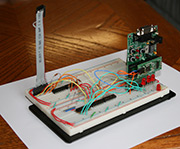
microSD Card Testing Setup
The major accomplishment for the day was writing most of the SD card driver for the 9S12. I worked using the code supplied from the FlashGenie website as a base. I went through line by line trying to understand why each instruction was needed. I removed all of the parts that were not required for simple read and write functionality. This lead to code that is more concise and easier to understand than the code from FlashGenie. By the end of the night, the 9S12 was able to successfully read data from the microSD card. The initial source code is available here: Team 10 Software v0.0
February 1, 2008 (2 hours):
Finished the basic SD card driver by adding a write function. After coding everything, I tested it to make sure it works properly. I wrote a simple Linux program to open a device file and output a data block in hex in the same manner as the microcontroller. Low level device access is required since all operations that function currently ignore the FAT16 file system on the card. Windows provides no easy way to directly interact with a drive. Linux, on the other hand, makes this task trivially easy. The program simple fopens /dev/sdf and reads in binary data. Using this program, I was able to verify that the 9S12C32 could indeed read and write to the SD card properly. As an interesting trick, I located the block offset of a text file on the card and had the microcontroller modify the contents. This worked as expected and opened up another possibility for the PC side SD card interaction. Assuming several large files can be maintained on the card unfragmented, the microcontroller would be able to write into the files without corrupting the file system. Then a windows application would be able to easily interact with the card as well. This is definitely a possibility to look into in the future.
February 2, 2008 (2 hours):
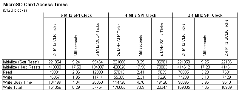
Tested SD card access times at various SPI clock frequencies. The general observation is that initialization and write times are basically invariant of clock speed, while read time shows improvement at higher speeds. Initializing the SD card takes 9.25ms with continuous voltage supply and 17.5ms immediately after power cycling the board. The read time decreases with increasing clock speed, but there are diminishing returns. More SPI clock cycles are needed at higher frequencies. Reading takes 2.06ms when using a 6 MHz SCLK. The total write time is around 7ms, although it seems to be only 6.29ms with a 6 MHz SCLK. The SD card spec claims that the card can be operated up to 25 MHz; however, communication failed with an SCLK speed of 12 MHz. It is likely that the improvised line level translator is to blame though. Timing information was achieved by making an ISR for the timer overflow interrupt that simply increments a 16 bit counter. A 32 bit timestamp can then be created by concatenating this counter with the TCNT register. A detailed timing table can be found here: MicroSD Card Access Times
WEEK 04 SUMMARY
Accomplishments: Settled on a microcontroller for the project and wrote a functional microSD card driver.
Weekly Work Total: 23 hours
Project Work Total: 46 hours
Week 05
February 5, 2008 (2 hours):
Went to RC Hobbies to see what products are available locally. The owner recommended buying a Super Cub instead of an Easy Star. He has the Super Cub in stock. Its fuselage has substantially more space. The only downside I can see is that it has a front mounted prop instead of top mounted. This would lead to more damaging crashes. It also comes with a feature called ACT that is designed to automatically recover the plane in case it stalls or dives to fast. However, I looked into this feature and it would seem that everyone advises against it. Apparently it just zeros the controls and waits for the plane to level out. Also, it won’t disengage this mode until the transmitter has its control sticks centered. Therefore, there would need to be a closed loop monitor for the system, or we could wire its sensors into our board. Camera mod of a Super Cub. I posted a question on this forum.
February 6, 2008 (1 hour):
Researched previous UAV R/C planes. One particularly valuable resource is DIY Drones. I remembered this from the keynote speech that Chris Anderson gave during NI Week last year. He uses more expensive parts, but it would be a good list to model our purchasing after. Particularly, I believe we will need to add further sensors to our project so that it can measure orientation with respect to the ground. Gyros or accelerometers would be an obvious choice, but it seems that IR sensors are also effective, and would be potentially much easier to integrate. Also, there is a commercial off-the-shelf supplier of RC autopilot systems: Pico Pilot. This would be useful during a discussion of current competing products.
February 7, 2008 (3 hours):
Posted on the DIY Drones forum asking for advice about UAV components. Chris Anderson, the Editor in Chief of Wired Magazine, promptly replied with a lot of advice. The Super Cub is out, but I am waiting on a response about the EasyStar. If that too is unacceptable, then the EasyGlider Electric should probably work for us. It has ailerons which would allow for stabilization. A quad thermopile setup should be sufficient to measure tilt angle. Paul found these thermopiles: MLX90247 on digikey. Various forum postings talk about GPS altitude measures possibly being flaky. In this case, it might also be wise to add this absolute pressure IC: MPXA6115A to measure altitude. Chris also suggested using a 5Hz GPS module. The Garmin 15L is only 1Hz. The Garmin 18 5Hz would work perfectly, except that it weighs at least 3oz without the cable and costs $200. A much better choice would be the ETek EB-85A. This module weighs only 0.5oz and appears to be just as capable. The only downsides I see are that it has a less sensitive antenna than the Garmin 18 and the documentation seems sparing. Since the project will be flying, I don’t think that we will have any signal reception issues. The documentation should still be sufficient to use it effectively as it just has an RS-232 interface sending out standard NMEA sentences.
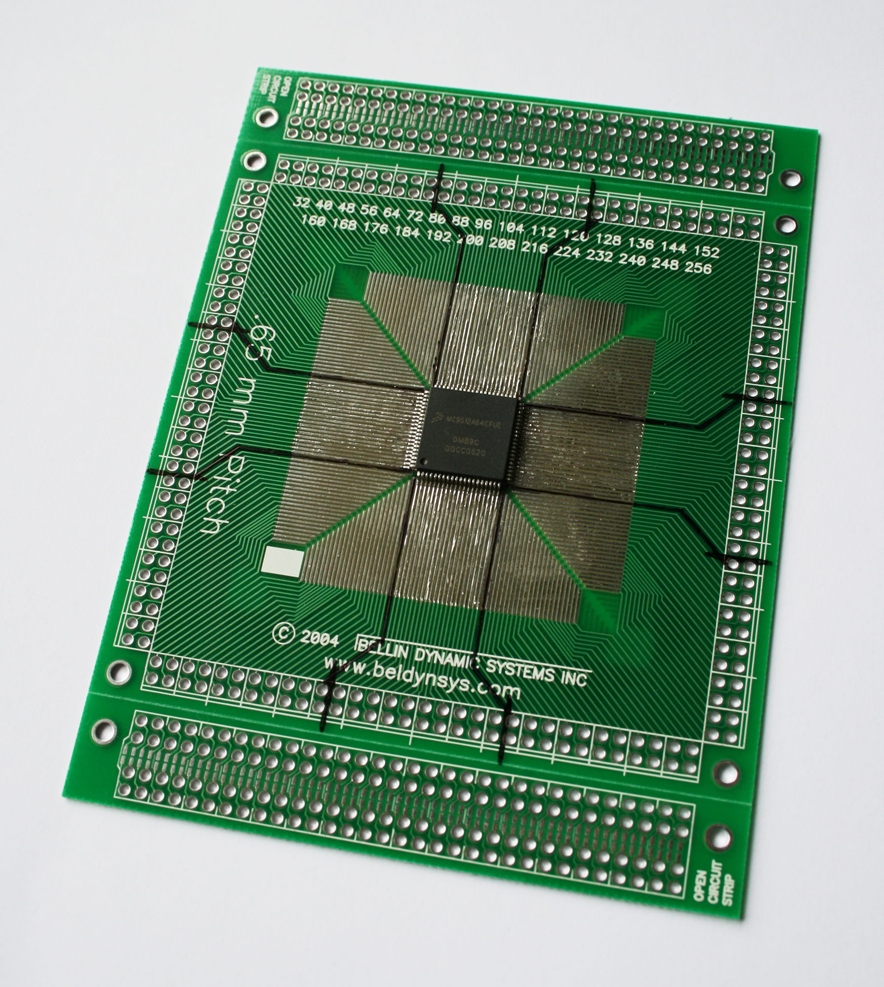
I also soldered a sample 9S12A64 to the breakout board that Paul obtained from Chuck. It was an exciting experience, but wasn’t too difficult. The board needs a clock and PLL circuit before it can do anything useful. I think it would be possible to rig additional surface mount components onto the breakout board. It has many unused pads to attach parts to. The capacitors and resistors in the lab should be sufficient for this circuit. We just need to acquire an 8 MHz to 16 MHz oscillator now. I’m not sure what frequency would be most appropriate, but my guess is that 8 MHz would be a good choice as that is what is on the 9S12C32 demo board.
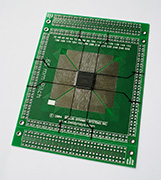
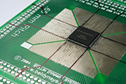
9S12C64 soldered to a breakout board
February 9, 2008 (2 hours):
Worked on improving the camera interface. I investigated the circuit boards of the R707 further in order to gain access to the video button control and some means of power-on detection. I settled on the 3.3V SD card supply as a means of determining if the camera is turned on. This works because the SD card is active whenever the camera is active. Here is a copy of the updated R707 dongle pin out. I wrote a set of driver functions for the camera that can be easily ported to the final project. Unfortunately, this implementation used busy waiting to strobe the camera signals. Some of these hold times were on the order of 100ms which is an unacceptable amount of wasted time since the GPS module will be giving us new data every 200ms.
R707 with further interface wires attached
February 10, 2008 (3 hours):
Rewrote the camera driver to work using an event queue. The motivating factor for this setup is that clock cycles are not wasted by waiting for camera strobe signals. Issuing a command writes a character into a circular buffer. These characters are read out by a scheduler function which is called once in each main loop iteration. The scheduler determines when each command has completed by keeping track of a start timestamp and a current timestamp. These 32bit timestamps are generated by concatenating the timer count, TCNT, with a 16bit integer that is incremented on each timer overflow interrupt. The API is simple to use and described in camera.h. Here is a copy of the updated source code: Team 10 Software v1.0. I purchased a pqi 2GB SD card for $11 total on newegg for use in the camera. It should allow for ~160min of video or ~1100 photos.
I think that the camera interface will require two more wires before it is reliable. One will sense when an auto focus lock is achieved, the other will sense when the video function starts. Without them right now, the result of commands is sometimes unpredictable. For instance, to get a video to start recording, the video signal is strobed, then held low for a bit, and strobed again. This has the desired effect, but logically only one strobe should be required.
WEEK 05 SUMMARY
Accomplishments: Looked into previous R/C UAV projects and joined several forums asking for help. I wrote an event queue based camera driver that can be easily ported to the 9S12A64. I also began work on the 9S12A64 demo board.
Weekly Work Total: 11 hours
Project Work Total: 57 hours
Week 06
February 11, 2008 (4 hours):
Met as a team to purchase parts and discuss circuit design. I purchased a Multiplex Easy Glider Electric for $168.98. Matt bought a GPS module and Paul bought some thermopiles. I found a website that should be very useful to the team as we work on the plane. Lafayette Cloud Jockeys is an R/C flying club which runs an airfield at McAllister Park, just across the river from my apartment. I emailed the Claude Vest, the president of the club, to see what parts he recommends and what kind of assistance we can get once our parts arrive.
February 12, 2008 (4 hours):
Wrote a servo motor driver for the 9S12C32 which uses 16bit PWM channels. In the process I found that documentation for the C32 has conflicting descriptions of the PWM module. The PWM_8B6C Block Guide claims that there are 6 channels. However, the PIM_9C32 Block Guide says that there are only 5. I wrote a test routine to determine which was correct. I found that there are indeed only 5 channels. This means that only 2 16bit PWM signals can be generated on the C32. The A64 will not have this issue though because even with the absence of PWM pin 6, 4 16bit PWM signals can be generated. The updated source code can be found here: Team 10 Software v1.1.
February 13, 2008 (3 hours):
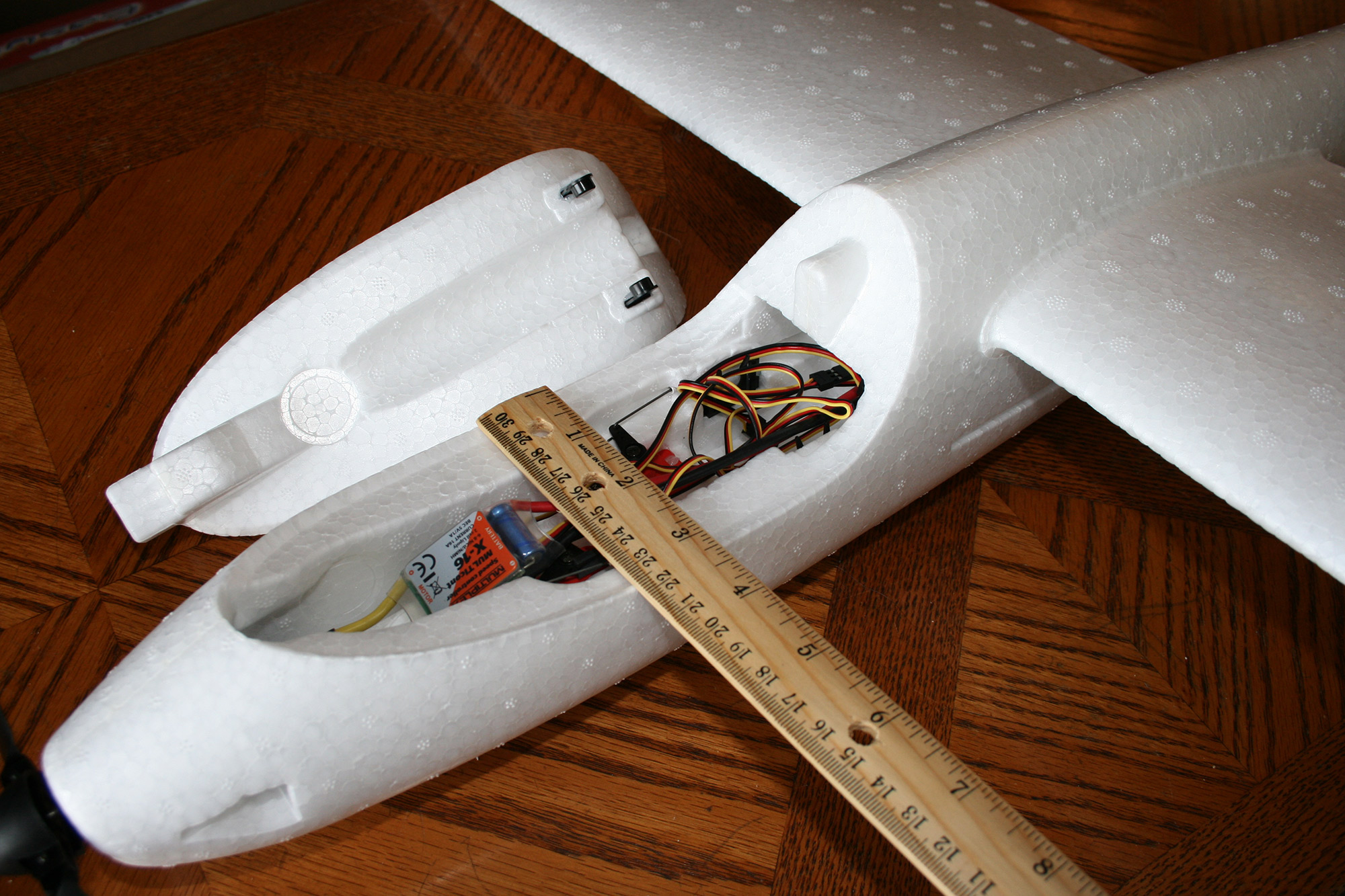
Inspected the Easy Glider Electric after it arrived today. Conveniently, the plane fuselage came almost fully assembled. The only structural work still required is gluing the rudder and elevator onto the tail with super glue. The most troubling thing that I noticed on initial inspection is that it is going to be hard to get the camera to fit into the fuselage. The only reasonable spot for it is in the location designed for the radio receiver. Even then, some substantial foam cutting will be required. It should be easy enough to mount our PCB onto the edges of the cockpit area above the aileron servos. We will just have hollow out the cockpit plug a little bit to make room.
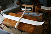
Easy Glider Electric out of the box
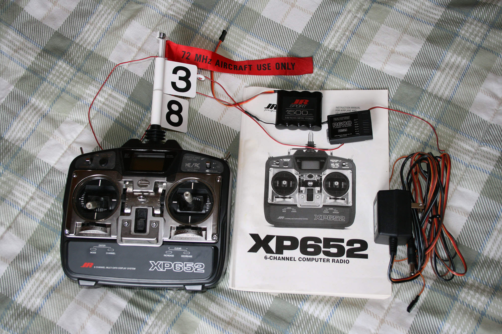
That evening, Daniel, Paul, and I went to the Lafayette Cloud Jockey’s monthly meeting. They will prove to be very helpful to the team. One of us needs to get an AMA license before they will let us fly at their airfield in McAllister Park. A few members of their club meet on Saturdays 9:00am-12:00pm at McAllister Park to build and tune planes. Once our plane is flight worthy, we can take it to them to test out. The highlight of the evening was that Ron Needham donated a complete 6ch radio system to our team. It is a JR XP652.
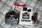
JR XP652 radio System
February 14, 2008 (3 hours):
Wrote a driver to read the servo signals coming out of the radio receiver. The output of the receiver is a square wave with 22ms period and a pulse length of 1.1-1.9ms. The servo signal is read into the microcontroller using an input capture pin which alternates from triggering on rising and falling edges. This technique is able to measure the incoming pulses accurately to the nearest 24MHz clock edge. The only downside is that a pulse of length greater than 2.73ms will overflow the 16bit counter and appear as a value near 0. However, in practice this will not be a problem because the servo input signal pulses are always less than 2ms in duration. It is entirely possible now to exactly duplicate the servo signal received with input capture to the 16bit output PWM pin. It is debatable whether or not the external multiplexer is necessary. Although, from a programming point of view, it is much harder to make one output bit fail than it is to make 4 PWM outputs fail. Team 10 Software v1.2
Playing with the servos yielded some interesting results. The servo input signal standard defines pulses every 20ms with a duration of 1-2ms. However, I was able to run the servos with periods of 20ms as well as 10ms. Also, full range lies well outside of the 1-2ms limits. The actual range between hard stops corresponds to 0.55 - 2.45ms. Assuming some margin of safety added beyond that as well, the microcontroller will still be able to drive the servos significantly further than the manual transmitter can. This will lead to more responsive control algorithms.
February 15, 2008 (2 hours):
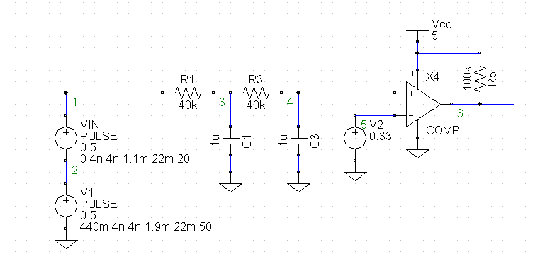
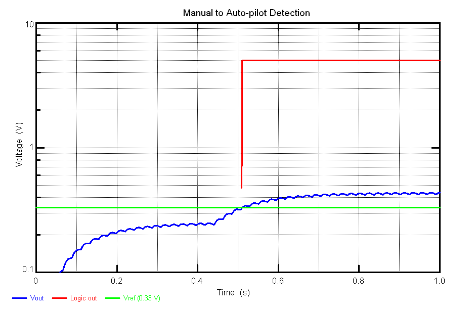
Designed a possible hardware solution to auto-pilot / manual selection. For safety purposes, it is desirable to have a hardware interlock that controls the auto-pilot / manual multiplexer directly. In case of microcontroller hardware failure or a software bug, it would guarantee that the plane could be brought back under manual control. The circuit I designed reads the radio auxiliary channel directly. It consists of a second order low pass filter which feeds into an analog comparator. It would definitely be capably of distinguishing between switch positions being sent by the transmitter. I have included a waveform produced using TopSPICE showing operation from powered off, to manual, and finally, to auto-pilot at 440ms.
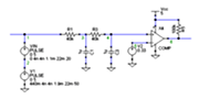
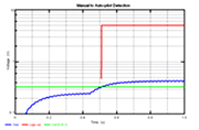
Manual to auto-pilot detection circuit
Upon further consideration I realized that the choice of hardware vs. software control of the servo multiplexer is not as straight forward as it appears. One disastrous scenario would involve the plane operating under auto-pilot with hardware control of the servo multiplexer. If it were to fly out of range of the radio transmitter, it would instantly switch over to manual control. However, being out of range of the transmitter would mean that manual control is impossible and thus the plane would crash. It would be possible to invert the meanings of the servo signal so that no signal corresponds to auto-pilot. Further thought needs to be put toward this problem. Additionally, it might be acceptable to fly outside of radio range to allow for better utilization of the GPS capabilities.
February 17, 2008 (1 hour):
Purchased an RC Smart 3900 mAh 3S Li-Po battery on eBay for $39 per Daniel’s request. I have misgivings about the quality and the shipping time. This forum post as well as this post indicate that RC Smart batteries are bad quality. At the very least, we will have to open it up and inspect the connections. Perhaps we will also end up buying one of these Hecell 25C 4000 mAh batteries. This seller is recommended in the forum posts. We still need to purchase a Li-Po charger (with balancer built in) that can handle either battery.
WEEK 06 SUMMARY
Accomplishments: Received the plane for the project as well as the radio system. We met several members of the Lafayette Cloud Jockeys who will be very helpful in the future. I wrote drivers for radio signal decoding as well as servo control.
Weekly Work Total: 17 hours
Project Work Total: 74 hours
Week 07
February 18, 2008 (2 hours):
Soldered two more wires onto the HP R707 camera. I was not satisfied with the operation of the camera driver using solely time based signal strobing. The video recording functionality in particular was quite non-deterministic in terms of how many strobes were required to get it started. I was able to identify the signals on the camera PCB that fed into the N-FETs driving the auto-focus lock and video active LEDs. I routed the signals through the darlington array and tested the output with LEDs. These signals will make the camera functionality reliable. I will amend the camera driver code soon to use them.
February 20, 2008 (2 hours):
Produced an OrCAD drawing of the hardware autopilot/manual selector so that Matt could integrate it into the project. This entailed relearning OrCAD as I last used it during ECE 270 labs. The process was aggravating to me, but hilarious to Matt. We decided to go with the best of both worlds for the servo multiplexer select line. There will be a jumper on the board to change between hardware and software control. An executive decision was made to have transmitter loss show up at autopilot selection. This should in theory save the plane if it were to fly out of radio range while being human operated. I also tried to help Daniel into motor and speed controller selection. There should be a way to connect it to our plane. My roommate said he will machine us a mounting plate for it if need be.
February 21, 2008 (1 hour):
Stopped by the senior design lab between classes to play with Paul’s thermopile circuit. I found it to be a fun device which is surprisingly sensitive. It is able to greatly increase its output with my hand over it. I will also saturate all the way to 0V with a snowball over it. Having a potentiometer in the amplifier circuit for each thermopile is essential as the range of temperature differences we will see in the sky is currently unknown. I looked at the breakout board with the hopes of adding a clock and PLL circuit to it directly. I think it should be possible to selective scrape off traces to form pads for surface mount components. The only questionable part is whether or not the oscillator and PLL will work over inch long fly wires.
February 22, 2008 (9 hours):
Manufactured a makeshift development board for the 9S12A64 microcontroller. This started by using a Drimel to hand etch the traces on the breakout board. I was able to form pads to solder the surface mount components onto. There is a surface mounted through-hole resistor because there were no 10 Mohm 1206 resistors in the cabinet. Once the surface mount components were in place, I focused on the power supply. I used a simple 5V linear regulator in an effort to get finished as quickly as possible. Connecting all of the ground and positive wires was extremely tedious as I had to continually count pins on the micro to ensure I was connecting to the correct pins. I also decided to use through-hole bypass capacitors for simplicity. I ended my construction after adding the BDM and reset circuits. Having been in the lab continuously for 9hrs I was ready to stop but I wanted to do some sort of testing. I was able to measure the signals going into XTAL, EXTAL, and XFC. The crystal was producing a beautiful 8 MHz sine wave. The PLL waveform showed an 8 MHz carrier frequency also with a higher order frequency inside it. I should be able to begin writing and testing software for the A64 now.


9S12A64 prototype development board
WEEK 07 SUMMARY
Accomplishments: Constructed a prototype 9S12A64 development board. I also helped to finalize the project schematic.
Weekly Work Total: 14 hours
Project Work Total: 88 hours
Week 08
February 25, 2008 (4 hours):
Met as a team to compile the design review presentation.
February 26, 2008 (5 hours):
Finalized design review presentation and met to go through a dry run. We ran into some fun while trying to print out the powerpoint slides for our presentation. Both of the printers in MSEE 189 were down so we went into the VISE lab next door. We then fought linux in an effort to get both duplex printing and two slides per sheet.
February 27, 2008 (3 hours):
Interfaced the EB-85A GPS receiver to a PC serial port. I was able to receive NMEA sentences from it as well send it commands. Particularly, I was able to send it a command so that it only sends two useful sentences instead of the default of lots of data.
February 28, 2008 (7 hours):
Began work on a GPS driver. The design is based upon interrupted buffer filling along with polling data translation. The current development is taking place on a PC because I have not had time to begin work on the A64 prototype and I would need two SCI ports if I was reading from the GPS unit with a microcontroller. I am writing the source code so that it will be easy to port into a 9S12 microcontroller.
February 29, 2008 (3 hours):
Finished the preliminary GPS driver for use on a PC. The driver can be seen in the latest version of the team software: Team 10 Software v1.3
March 2, 2008 (10 hours):
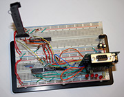
Began testing the peripherals modules on the A64 prototype. I soldered together the translation logic needed to test the GPS receiver. Most of the pieces are also in place for the MicroSD card. Initial programming on the A64 took place using a BDM dongle. I managed to edit the 9S12 serial monitor source code to work on the A64 then I loaded it onto the microcontroller. CodeWarrior is now able to reprogram the prototype over the SCI port. The project is set up using the small memory model. I initially tried using a banked memory module, but the timer ISR would not function for some reason. The current state of the 9S12A64 project merely pipes the data from the GPS receiver out to the PC. I am in the process of porting each module from the C32 project to the A64 project, only small modifications are needed. The preliminary A64 source code can be seen in the latest version of the team software: Team 10 Software v2.0

9S12A64 prototype peripherals
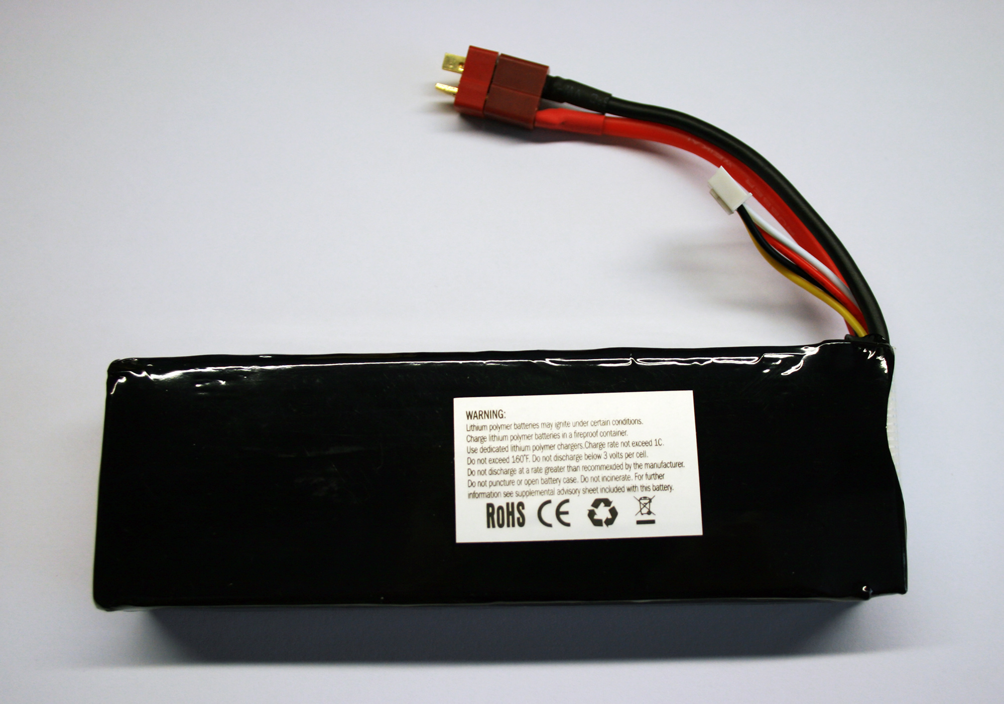
The RC Smart battery arrived from Hong Kong. I ripped off the outer covering per various website recommendations. I decided against pulling off the filament tape because I had no filament tape or electrical tape to replace it with. I took the plane, battery, and camera over to Daniel so that he can work on getting the construction going.
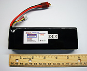
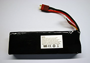
3900 mAh 3 cell Li-po RC Smart battery
WEEK 08 SUMMARY
Accomplishments: Began programming on the A64 prototype. We had a very successful design review.
Weekly Work Total: 32 hours
Project Work Total: 120 hours
Week 09
March 3, 2008 (3 hours):
Continued writing the GPS module for use on the 9S12A64. The buffering and translation functions should operate correctly. However, the SCI0 receiver interrupt which handles the buffering does not run properly. I know that data is coming into SCI0 but the interrupt code is never run. I added a line at the beginning of the interrupt to toggle an LED, but it never comes on. Additionally, the main loop hangs after its first debug output. I suspect that the interrupt vector table entry for the SCI0 receive interrupt is not correct. However, I followed the same procedure when declaring it as I did for the other ISRs, so I don’t know why it’s not working.
March 5, 2008 (3 hours):
We arranged to have our PCB check-off immediately following the progress briefings. The overall process took longer than expected as we waited for various people to show up. In the end though, it was successful.
WEEK 09 SUMMARY
Accomplishments: Worked on the GPS module using the 9S12A64 and RTMed the PCB.
Weekly Work Total: 6 hours
Project Work Total: 126 hours
Week 10
WEEK 10 SUMMARY
Accomplishments: Spring Break
Weekly Work Total: 0 hours
Project Work Total: 126 hours
Week 11
March 18, 2008 (5 hours):
Began work on the Software Design Narrative homework. Initially learned the proper IEEE citation format, and then compiled a list of sources. I ended with the design consideration and introduction sections finished. I also made a quick PowerPoint presentation for use in TSCP 6.
March 20, 2008 (5 hours):
Completed the Software Design Narrative homework. Due to the large number of software modules and connected devices, the body of the homework ended up being 6.5 pages long.
WEEK 11 SUMMARY
Accomplishments: Wrote and submitted the Software Design Narrative homework.
Weekly Work Total: 10 hours
Project Work Total: 136 hours
Week 12
March 24, 2008 (2 hours):
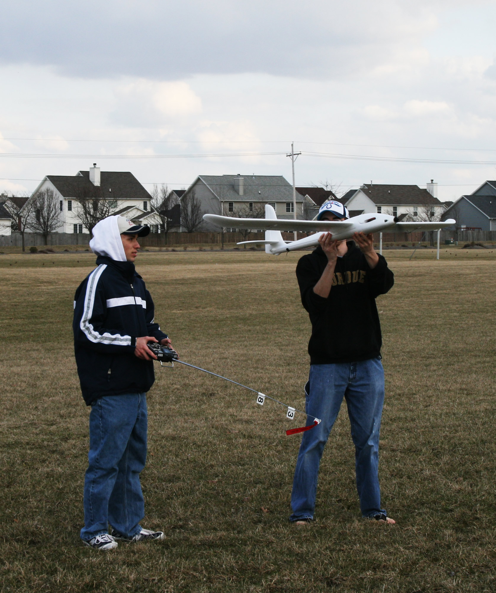
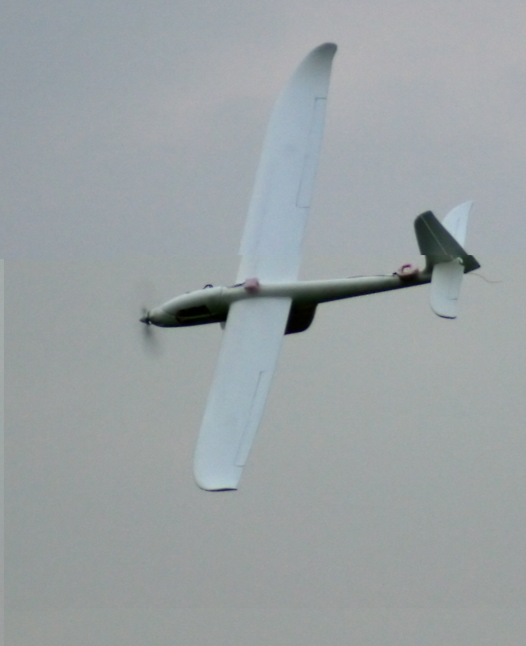
Daniel and I met with Corben Meyer for the first time and had the maiden flight of our plane. We flew it with stock components and a 2 cell Lipo battery. It flew beautifully without any need for trimming or balance adjustment. The stock motor had enough power that Corben was able to fly it through a loop. Eventually he got it at a cruising altitude and set the throttle so that it wouldn’t drop its elevation. He handed me the controller and I had my first experience with an R/C aircraft. The first 5 min were choppy as I learned how to move the elevator effectively, but eventually I got a handle for the controls. It really is an easy aircraft to fly. However, I attempted to land without first getting Corben’s advice and crashed the plane. The tailfin snapped off because it had been improperly glued on using foam safe super glue. The instruction manual calls for standard, non-foam safe, super glue. Other than that, no other damage was sustained.

The first launch and some unpowered flight
March 25, 2008 (6 hours):
Confirmed proper functionality of the GPS buffering and translation functions. I simulated an interrupt for the SCI receiver by having the main loop simply busy wait on the SCI status register flag. This showed that GPS data was read from the GPS receiver correctly; however, the set up wasn’t useful to the final project as the main loop could do nothing but service the SCI input. I then set out to find a way for a PC to read the binary storage format used by the microcontroller. Printing out the raw memory of the microcontroller showed that it stores integers in big endian format. Linux on the other hand uses little endian. Therefore, the conversion function merely calls ntohl and ntohs to convert the endianness of GPS values after they have been read in. Later, I began soldering the SD card interface onto my prototype board so that I could confirm that the SD code was functional.
March 26, 2008 (8 hours):
Matt and I met with Sean Henady of Aerial Image, Inc. His company is located up in the research park. When we arrived, he and his group were flying their helicopter UAV. It is very impressive system. I envied the Canon EOS 5D they had hanging off of the bottom. It puts our HP camera to shame. While we were there, we got the contact information of Nick Setar. He is the one responsible for the control algorithm of their helicopters. He suggested that a PID controller running at 6 Hz would be sufficient to stabilize and steer our plane. His experience will be invaluable once we have the plane flying autonomously.
Later in the day I finished soldering the SD card circuitry on my prototype board and then began debugging. I noticed immediately that the card was not responding properly to commands. The SPI module always received a value of 0xFF. This could have been caused by several factors and I carefully check each one. Eventually I reached the limit of the testing I could do in my apartment and had to go into the lab. I found that the SPI module was not sending any data out of the microcontroller pins. I searched all over the internet and eventually found the culprit. Port M of the A64 is shared by SPI and CAN. Out of reset, CAN is in control. Bit 4 of MODRR must be set for the SPI module to route through port M. Once I added this initialization, the SD card functions operated exactly as they had on my C32 setup. I was disappointed by the simple nature of this error and decided to get some more work done while I was in lab. I ended up soldering the majority of the power supply components onto the PCB.
March 27, 2008 (9 hours):
Solved the problem with the SCI0 receive interrupt. I spent a huge amount of time trying to figure out what would cause the receive interrupt to never fire. For awhile I thought it had something to do with a problem outline in one of the errata documents for the chip. I scoured various web forums until I found one talking about the serial monitor program. Apparently it is set up to catch the SCI0 interrupt. When I initially edited the serial monitor code to work with the A64, I neglected to edit the interrupt vector table. The fix was as simple as switching the ISR in the monitor to use SCI1. The GPS unit worked immediately after fixing the monitor. I spent the rest of the day fiddling with the GPS module in an effort to get it to log waypoint onto the MicroSD card. The program packs 15 GPS readings into a 512 byte buffer then writes the buffer to the SD card; immediately after, it writes an updated count value to the head of the waypoint list. This ensures that the PC knows how much data to read in.
I wanted to get some raw GPS data to play with, so I took my setup out to my car and tossed everything on the dashboard. I powered it off of a wall wart plugged into an inverter. I had my laptop in the passenger seat to display real time data coming off of the GPS receiver. I drove a loop around campus for about a half hour and stopped briefly at a few landmarks in an effort to determine the accuracy of the unit. Upon plugging the SD card into my computer, I found that no points had been recorded. Dismayed, I turned debug statements on, and ran it again. Apparently the card detection wire broke off of the pad it was soldered to. The microcontroller sensed this as no card inserted and thus ignored any I/O requests. I changed card insertion definition to always be true to temporarily fix the problem.
Still determined to get some data, I went out in my car again. I drove a short loop, and then checked the data on a PC. It looked good in binary form. I researched methods for getting data into Google Earth and settled on the gpx format. Next, I wrote a program to convert the binary output from the MicroSD card to gpx format. This program, gpxconvert, is included in the latest software distribution: Team 10 Software v2.1, along with the microcontroller code additions. Running the loop drive data through this program produces this gpx file. This file can then be opened with Google Earth. The first observation is that the readings drift a lot at times. The values are off by as much as 15ft while turning around corners, but probably within 1ft while moving straight at relatively low velocity. The altitude data appears to be extremely accurate, contrary to what we have heard before. While driving, 8-11 satellites were shown to be in view. This GPS module should work very well on the plane as it will have a perfect view of a clear sky.
March 28, 2008 (6 hours):
Researched fixed point methods for Cos and Arctan. CORDIC looks like a good method to get relatively high precision. However, after playing with values, I realized that at least for Cos, a lookup table is accurate enough. I picked two points in a field on Google Earth to test with. It gave me a distance of 415ft. Calculating the distance by hand also gave me 415ft when using the exact latitude in the correction factor. Longitude degrees get closer together as they approach the poles. To compensate, you multiply longitude deltas by the cos(latitude). When I recalculated the distance after rounding the latitude to the nearest degree for the correction term, I ended up with a distance of 417ft. This error is on the same order as that of the GPS receiver, so rounding is acceptable. I still need to figure out how to determine Arctan and Sqrt so that I can calculate the distance and direction to a destination.
I wanted to determine the accuracy of the speed and bearing reading of the GPS module so I figured out a way to display them on a path in Google Earth. There is no native means in Google Earth to draw a vector field instead of a piecewise linear path. My solution was to add waypoints in the conversion process to represent these vectors. After the program modification was complete, I observed the results in Google Earth. I was less than impressed. While going straight the bearing is almost perfect. However, while turning, the heading lags behind the GPS waypoints. This could have a major impact on our plane as turning correctly is extremely important. The worst case solution would be to calculate bearing from successive waypoints instead of trusting the value from the GPS module. We will know if the readings are acceptable once the plane is flying with the PCB on board.
March 29, 2008 (9 hours):
Ported and tested the code for radio and servo modules. Both modules are done and working properly. I soldered the necessary interface circuitry onto my prototype board so that I could test the code. The work was fairly straight forward. I did find a problem with the overall system setup. The motor speed controller outputs 5V. The PCB ties this output directly to the board 5V. This will lead to fighting between the two regulators. There are two ways to deal with the problem.
The first, which I decided to use on my prototype, is to disconnect the power wire going into the speed controller. This way, the board still supplies the power for the servos. However, BEC on speed controller requires a load to function. I placed a 720ohm resistor between ground and the power wire to create a minimal load.
The second technique for dealing with the 5V supply is to cut the trace on the PCB leading to the servos. This is convenient because it requires no external circuit modification. Also, it means that the BEC on the speed controller will power the servos. This has the benefit of reducing the load of the regulator on the PCB. Unfortunately, this might cause a small drop in overall efficiency of the system because the BEC uses a linear regulator. Further consideration is needed for this problem.
March 30, 2008 (6 hours):
Ported and tested the code for the camera module. It works well thanks to the feedback inputs. I soldered camera interface circuitry onto the prototype board to enable testing. In the process of my testing, I found another problem with the schematic. The COM leg, pin 9, coming off of ULN2003A, U11, will need to be cut off. Connecting COM to ground has the same effect as driving all of the transistors all of the time. The updated software including radio, servo, and camera modules can be found here: Team 10 Software v2.2.

State of A64 prototype board
WEEK 12 SUMMARY
Accomplishments: Successfully ported and tested all major code modules. Everything is done and working besides navigation and stabilization.
Weekly Work Total: 46 hours
Project Work Total: 182 hours
Week 13
March 31, 2008 (1 hour):
Took large 22ohm resistors into the lab to test load the switching regulators. Both the 3.3 and 5V supplies exhibited about 10mVpp of noise as well as 100mVpp spikes at the switching frequency. More capacitance may be needed on the output. The 40.2kohm resistors for R48, R49 were missing; they were replaced with 49.9kohm ones after determining that the new value would function fine.
April 1, 2008 (6 hours):
Soldered the micro, crystal oscillator, bypass caps, and LEDs onto the PCB. I used a scope to ensure that that supply voltages were correct and that the clock was operating. I was able to successfully program the micro using a BDM connector. The test program initialized all of registers, and then pulsed the on-board LEDs. I found that some of the resistors soldered to the board had incorrect values and removed them. The error stemmed from Paul referring to an out-of-date BOM instead of the schematic while he was soldering components on. Also, R20 and R55 labels were found to be swapped on the PCB silkscreen.
Later in the day, I began work on HW11 by producing the block graphics and the FMECA tables. This information was then put into the powerpoint presentation for TCSP8.
April 2, 2008 (4 hours):
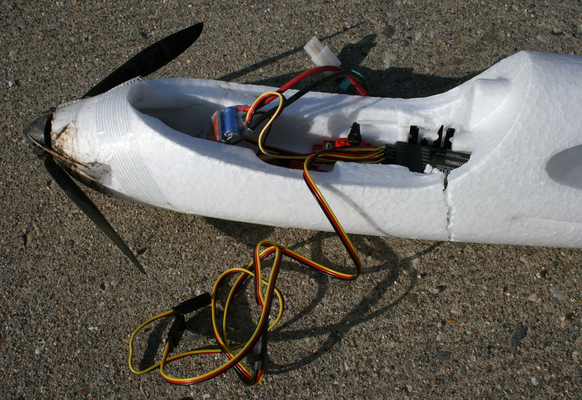
This was a nice sunny day so I really wanted to get some flight time in. However, the plane had to first be repaired. The tailfin had broken off during the maiden flight because Daniel glued it on with the wrong variety of super glue. The instruction manual specifically calls for non-foam safe glue. I went out to buy some super glue along with sandpaper, balsa, and filament tape. Once all of the supplies were acquired, I went about attaching the tailfin. The first step was to remove the foam safe super glue; it chipped off easily with just a fingernail. I chose to use balsa for reinforcement because it is extremely porous and surprisingly strong for its weight. Gluing the fin on was straightforward once the balsa spikes were in place.
With the plane repaired, I met Daniel at the field next to the International Sports Club. In retrospect, it was clearly too windy to fly, but I had gone to the effort of fixing the plane and I wanted to at least try. We started with some unpowered tosses just to try to maneuver in the wind. Eventually we upgraded to powered flight. I found that flying head on into the wind was fine, but as soon as you turn to one side, the wings turn into sails and the plane is thrown toward the ground. This effect led every launch to end in a crash of some sort. Fortunately, it usually hit the ground wing first which has the convenient tendency of just pulling the wings off a little bit to absorb the impact without breaking anything. The final crash though, hit hard on the nose of the plane. This resulted in the cockpit breaking halfway apart directly behind a band of filament tape used to hold the cockpit plug down. The damage was unfortunate, but repaired on the spot with superglue. In the future, the fuselage will be reinforced with a band of filament tape to avoid such cracks. Realistically, the Global Pigeon will only be useful on clear sunny days with wind below 5mph. That evening, I spent some time working on the body of HW11.

First major crash damage to the plane
April 3, 2008 (3 hours):
Finished and submitted HW11.
April 4, 2008 (12 hours):
Began verifying functionality of all software modules on the PCB. Initially the MicroSD and GPS interfaces did not work. After some investigation it was found that some of the pins on the voltage translator ICs had not been soldered down. I then had to check and resolder all of the SMTs because Paul had improperly soldered several of them.
The hardware autopilot detection circuit was also not function. I found that Paul solder a 49.9k resistor on R50 instead of 6.98k. I had to pull it off and put the right one on. Additionally, the pinout of U18 is wrong on the PCB; the V+ and –In pins are swapped. It will take some creative fly wiring to fix the error. The easiest choice will probably be to cut the traces on the underside and fly wire between them.
April 5, 2008 (8 hours):
My primary objective for the day was to get some flight time in due to the nice weather. Before I could go out, I needed make some dongles so that the PCB could be mounted in the cockpit to collect data. The most important connect was the one going to the radio. After soldering all of the wires in I tried to test it out. The results were quite flaky. It seemed that the connector made a poor connection to the header. Jiggling it around let to jitter in the servos. At that point it was already getting late so I decided to meet up with Corben just to get some manual flight in.
We were flying at a different field this time. It is located about 30min south of campus. It was moderately windy, but Corben instructed us in how to fly. Once again the fly flew quite well. Both Daniel and I got some flight time in. There were some minor crashes but the plane is quite resilient. At one point the rudder to servo connection broke and it still flew without a problem. The final landing broke the servo horn in left aileron. According to Corben it is a simple $2 fix, but we didn’t have the part on hand. Recharging the Lipo put back 1428mAhr into it of its 2170mAhr capacity.
While we were at the airfield I wanted to show Corben the GPS setup. I got it all out and running, but the GPS receiver would not pick up any satellites after 5min. It usually acquires around 7 satellites in 2min. I let sit for half an hour and it eventually found 3 satellites. I left it all running and drove back to my apartment. When I got back, I found that it had lost a lock on all of the satellites as soon as I started moving. I fear that the GPS module is broken, this seems to be symptomatic of the antenna connection failing as it eventually got a link to a few satellite when it had a perfectly unobstructed view of the sky. It should have easily been able to pick up 11 satellites at the site. I’ll try running it tomorrow to see if it can be made to work.
April 6, 2008 (6 hours):
Attempted to figure out the problem with the GPS module. I tried several different combinations of interfaces in an effort to eliminate any possibility of external error factors. I connected the GPS receiver to both the PCB and my prototype board. Both showed the same results. The GPS receiver is outputting valid packets, but it is never getting a lock on any satellites. I took everything out into the middle of the engineering mall and sat there for 15min with no results. Next I tried direct communication between the GPS receiver and my laptop using the software provided by the manufacturer. It was able to receive packets as well as send data and get acknowledgements. This proved that no connections to the GPS receiver were malfunctioning. I next tried to find help on the internet. One site suggested that the receiver was very susceptible to noise on the voltage supply line. I was skeptical that the linear regulator on my prototype was outputting much noise, but I tried a further test case. I took everything out to my car and powered my prototype board off of a wall wart plugged into an inverter. This is the exact setup I used last week to get very precise data corresponding to a driving route. Unfortunately, I was met with the same results. The microcontroller received packets, but the GPS receiver never found any satellites. I am confident that the GPS receiver is broken internally somehow. This is extremely discouraging given the timeline that we have remaining. I’m not sure how we are going to rectify the situation. In retrospect, I think that the GPS receiver fell off of the lab bench last week and hit the floor. If that caused the malfunction, then I’m not sure a new fully functional receiver would even be appropriate for flight on the plane. It would have to be able to withstand the shock of repeated crashes.
WEEK 13 SUMMARY
Accomplishments: Finished PCB population and verified functionality of all modules. I practiced flying the plane manually. I found out and verified that the GPS receiver is broken.
Weekly Work Total: 34 hours
Project Work Total: 216 hours
Week 14
April 7, 2008 (9 hours):
I began work with a shopping adventure. I hit up several stores to get all of the parts I needed. I found replacement headers and receptacles at Lafayette Electronics. These should ensure that the connections off of the board are solid. I went to RC Hobbies to get servo arms and a pair of deans connectors. I wanted to get a Lipo balancing adapter, but I didn’t have the battery and charger with me for reference. Next I hit up Hobby Lobby and got some Velcro strap to tie down the cockpit plug and camera. Finally, I went to Lowes and got some 600 grit sandpaper to smooth the plane with. I got some foam straps from an ME senior design team so that we can mount the camera and thermopiles.
I wanted to get the thermopiles all working so I began work on the navigation software module. I used the RTI interrupt to produce consistent sensor readings. It runs at about 300 Hz. A stabilization event occurs at 10 Hz. Eventually this function will be used to send values to the servos. The thermopile values are read for 8 cycles immediately preceding a control event and averaged together. Once I had the code working, I soldered all of the thermopile sensors onto twisted pairs of 28awg wire. I was meticulous in my soldering because I didn’t want to have to redo it.
With all of the thermopiles attached, I found that the output of the amplifiers was ridiculously noisy. I was able to isolate the case to be the 2.5V regulator. Our schematic did not load it properly to reach the quiescent current nor did it include input and output capacitors. I soldered a 1kohm resistor and two capacitors totally 5.7uF between the 2.5V rail and ground. This seemed to greatly improve the thermopile readings. However, the therm2 channel was producing values higher than the other channels. This difference was unfortunately not linear as I found when putting a warm object in front of the sensors. I think the deviation might be caused by the orientation of the loading components I added on.
Additionally, I realized that the Vsense input going into the microcontroller had a value of 8V when using an 8V supply. For some reason, the voltage divider was not working. The port pin used for that input is burned out. Fortunately it didn’t take the entire microcontroller with it. I removed R20 to eliminate this out of bounds input. I also found that switching between the user application and the serial monitor is non-deterministic. Sometimes it is necessary to repeatedly power cycle the board in order to get the user program to run. I suspect that the run/boot selector may be improperly programmed, but I’m not sure.
Lastly, I weighed the PCB for the project. It has a mass of 1.40oz. The GPS cable, for reference, has a mass of 0.43oz. It would be a good idea to load the plane down with dead weight and try flying it manually to determine if the stock setup is powerful enough. If it is not, we will need to order all of the parts required to upgrade to a 3 cell lipo and a brushless motor.
April 8, 2008 (6 hours):
I began writing a generic PID control system. It will be used for navigation and stabilization. The code should work, but it has not been tested. Paul had someone in another lab attempt to fix our GPS receiver. Unfortunately, the top face of the antenna was damaged in the process when realistically, only the connection on the inside needed to be resoldered. The module is in the same state as before where it will transmit packets, but never lock onto any satellites. Additionally, the PCB was acting in an extremely non-deterministic manner. Code would not run as expected. I guess is that there is a conflict with the interrupts and/or SCI ports. I couldn’t figure it out. The external connections may also be flaky. I contacted the people at Ohararp LLC to see if they would be willing to donate a GPS module to us.
April 9, 2008 (0 hours):
Purchased a new EB-85A GPS module from Ohararp LLC for $55 + shipping.
April 10, 2008 (8 hours):
Replaced the headers on the PCB with locking ones from Lafayette Electronics. This should fix the jitter I was seeing in the servos caused by flaky contacts. I made a dongle to go between the PCB and the radio receiver. I spent a lot of time constructing it as it is mission critical. I took raw data from the thermopiles and determined a scaling function so that they all output the same value at the same temperature. This was accomplished by taping all four of the thermopiles onto a piece of foam so that they would look in the same direction, and then recording the sensor readings at different temperatures. The scaling coefficients were determined by performing a linear regression on a TI-89.
April 11, 2008 (3 hours):
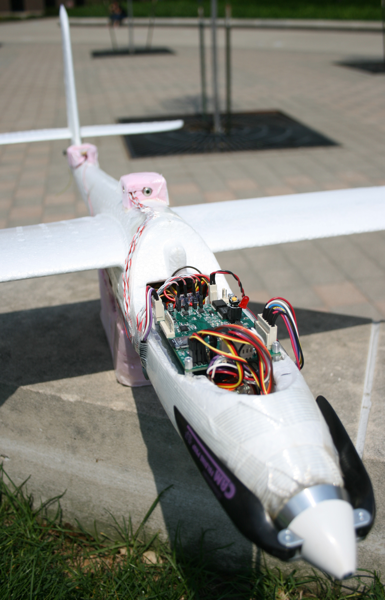
Determined a mounting technique for the PCB on the plane. I enlisted the help of my ME roommate in order to find a sound connection method. We chose to go with a pair of aluminum strips with machine screws going through them vertically into the PCB. The strips are then screwed and glued into the cockpit. The aluminum pieces were cut out, but not yet attached to the plane. Machine screws and nylon spacers are still needed.
April 13, 2008 (4 hours):
Wrote and tested a function on a PC to calculate the distance and bearing between GPS waypoints. The code should be directly transferable to the microcontroller as all calculations were done using 32 bit integers. The general technique involves using a cosine lookup table along with an iterative square root calculation. Values are bit shifted extensively to ensure that integer bounds are not broken. The output has more than enough precision for the Global Pigeon. The bearing measurement is accurate to +/-1deg. The distance measurement is at worst 1% too small. A graph of the error can be viewed on this spreadsheet. The updated source code release can be found here: Team 10 Software v2.4.
WEEK 14 SUMMARY
Accomplishments: Made preparations for attaching components onto the plane. I soldered robust dongles which are glitch free. I began writing the software for the navigation system.
Weekly Work Total: 30 hours
Project Work Total: 246 hours
Week 15
April 14, 2008 (9 hours):
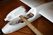
Ported distance and bearing code onto the microcontroller. The output is valid in the test cases so everything checks out. I mounted thermopiles on top of the fuselage in a small styrofoam box. This attachment method should work very well. A similar box will be used to hold the GPS module onto the tall. I also made a hideous foam case to hold the camera. It should protect the camera well; however, it is extremely large and not aerodynamic. Hopefully the plane can still fly while having it hang off of the bottom.
April 15, 2008 (10 hours):
Tested out the new GPS module. The initial run in the afternoon went well. It connected to 6 satellites quickly and got up to 10 after several minutes. The later run at night was less impressive. It only picked up 4 satellites after five minutes. While testing the module, I found that it was never responding to the commands sent from the micro. Investigation showed that the level translators for the GPS module were not working correctly and that the 2.8V regulatory did not have a constant output. The regulator simply required an output capacitor. The problem with the level translators was due to an error in the schematic. The direction pull resistors were connected backward. I swapped them around by soldering the resistors to nearby pads. I also soldered a comparator onto the PCB and fly wired between pins 4 and 5 to correct for the footprint error. Testing the comparator circuit with the radio transmitter showed it to be functional. However, after encapsulating it with hot glue, it seemed to not function correctly. I am not sure what is causing the problem. I noticed that the MicroSD connector came unsoldered on the back. This will need to be fixed tomorrow.
I wrote a menu based program for the microcontroller to quickly and definitively demonstrate completion of PSSC 2-5 to the course staff. Most of the code was already in place; however, I had to write a quick program on a PC to fulfill PSSC 5. GPS coordinates are stored in a list in a human readable file. A program is executed from Cygwin to write the list onto the MicroSD card at a known offset in a binary format. The microcontroller then reads the MicroSD card and prints out the list. The demonstration of the other PSSCs was relatively straightforward. The PSSC test code will remain in the main.c file for future reference. As an aside, the new 3 cell Li-po took in 1137mAhr when charged
April 16, 2008 (3 hours):
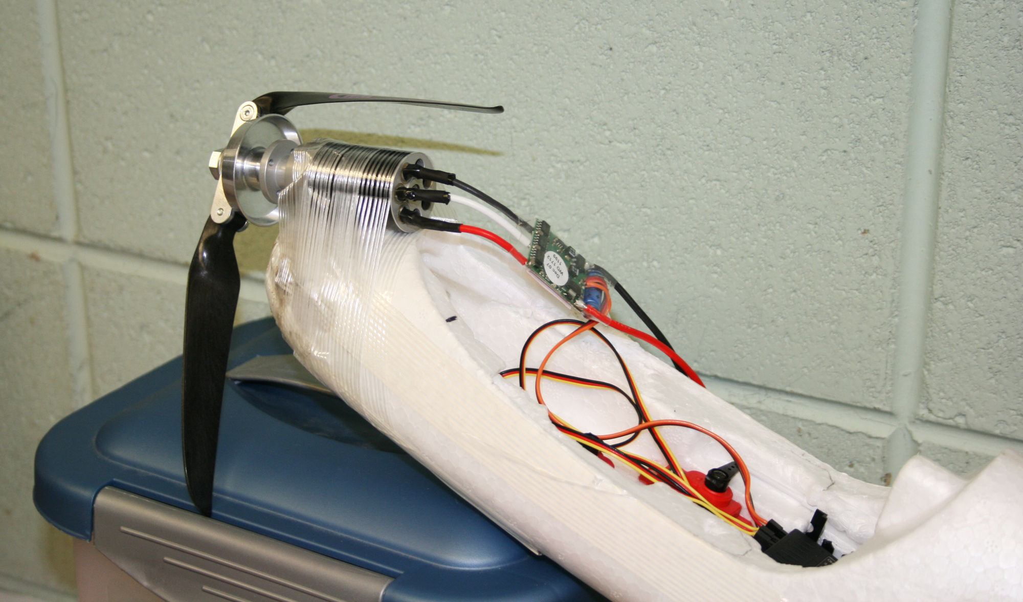
Had the design review and checked off PSSC 2-5 at the end. The check off process went as smoothly as expected. I soldered dean’s connectors onto the 3 cell Li-po battery and the new speed controller. I then determined the proper polarity for the brushless motor connections and soldered it to the speed controller. I acquired locktite from my roommate to secure the screws on the propeller. I wanted to know how powerful the new setup was so I attached the motor to the nose of the plane with filament tape and powered it up. The results were quite impressive. The new motor and bigger battery definitely provide more thrust. This should make the idea of flying with so much added weight saner.

Brushless motor initial test
April 17, 2008 (4 hours):
Made a blueprint for the holes that need to be milled into the LCD box. I scribed them onto the box itself and gave it to Chuck. He said that it should be done by Friday or Monday. I wanted to test how well the GPS module could give me a bearing error value for the purposes of steering toward a target. I set the center of the engineering fountain as my target and went out to walk around the engineering mall with the setup in a box. I quickly found that a brisk walk is required to get any kind of useful bearing and this made it challenging to test the overall accuracy of the setup. I decided to test the setup by taping it onto the handlebars of my bike. The setup was sketchy, but quite functional. I was able to approach the fountain from a distance while swerving and watch the error value swing from slightly positive to slightly negative. The module should easily be able to steer the plane to its waypoints. Later in the evening, I made slight modifications to the user manual and submitted it.
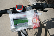
GPS target tracking on bicycle
April 20, 2008 (8 hours):
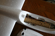
Soldered together the interior of the LCD box and its associated dongle. I cut out the slot in the fuselage for the bigger battery using a creative tool furnished by Chuck. I formed a plug for the camera compartment and secured it with a Velcro strap. I glued camera assembly onto to plane with its center of mass slightly in front of the designated center of mass of the plane. I glued PCB skis onto the sides of the fuselage. Unfortunately, the PCB must be removed to change the battery; however, it doesn’t take much time. I made a holder for the GPS module out of foam. I cut out the hole in the front of the plane to allow for the larger gearbox on the brushless motor. I secured the gearbox to the fuselage with hot glue on the front surface. I found that the center of mass of the plane was 60mm back from the leading edge of the wing instead of the manufacturer specified 70mm. Gluing the camera holder on was a bad idea; it will probably have to be cut off to adjust the center of back to the proper location.
WEEK 15 SUMMARY
Accomplishments: I fixed all of the hardware problems on the PCB and tested out the new GPS module. The GPS module works well according to the bicycle target homing experiment and should be able steer the plane effectively. I wrote a test program to quickly and accurately present the functionality of each of the non-flying PSSCs. This program was utilized for the PSSC check-off. I nearly completed all of the hardware work by attaching all of the components to the plane and soldering robust connectors. I constructed the LCD box because it allows for convenient and elegant display of diagnostic information.
Weekly Work Total: 34 hours
Project Work Total: 280 hours
Week 16
April 21, 2008 (9 hours):
I began by soldering the last of the connectors for peripheral components. This consisted of the camera interface and the GPS module. Once these were done, I found the center of mass of the planes with the wings on. It was still much too far forward, so I decided to move the camera holder. This entailed slicing through it parallel to the bottom of the plane, gluing a new piece of foam behind the old one, and then finally gluing the camera holder back down. The results are far from aesthetically pleasing, but the center of mass is now positioned where it ought to be.
Next I began getting the software in order so that it could log the radio inputs and thermopile readings as well as the GPS coordinates while flying. This involved significant alterations as the data logging had to be moved into the RTI interrupt handler. In this manner, data is logged 10 times per second. The hope is to get Corben to fly the plane and then model a PID controller in Matlab that can approximate his control values given the sensor inputs. I also set up the program so that the camera can be controlled manually using the switches on the top of the radio transmitter.
With the programming done, I began the final touches of the assembly process by taping down all of the loose wires on the outside. I wanted to attempt a flight just to see if it would glide appropriately so I enlisted the help of my roommate. He tossed it out into the engineering mall and I throttled it up a little. It dived hard into the grass and dislodged the drive motor from the hot glue mount. This is actually somewhat convenient as it can now move forward against the glue during flight, then move backward and hit the foam of the nose when crashing.
I performed a final test by walking around the Civil building while logging data. I modified my previous PC software to accept the additional fields then imported the data into Matlab. There I graphed it in 3D to see the path I had walked. There was a significant deviation in the altitude reported. I think that the altitude reading will get better the longer the GPS module is running. Also, I think it will report a better value as the plane is moving at high speed.
April 22, 2008 (3 hours):
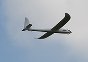
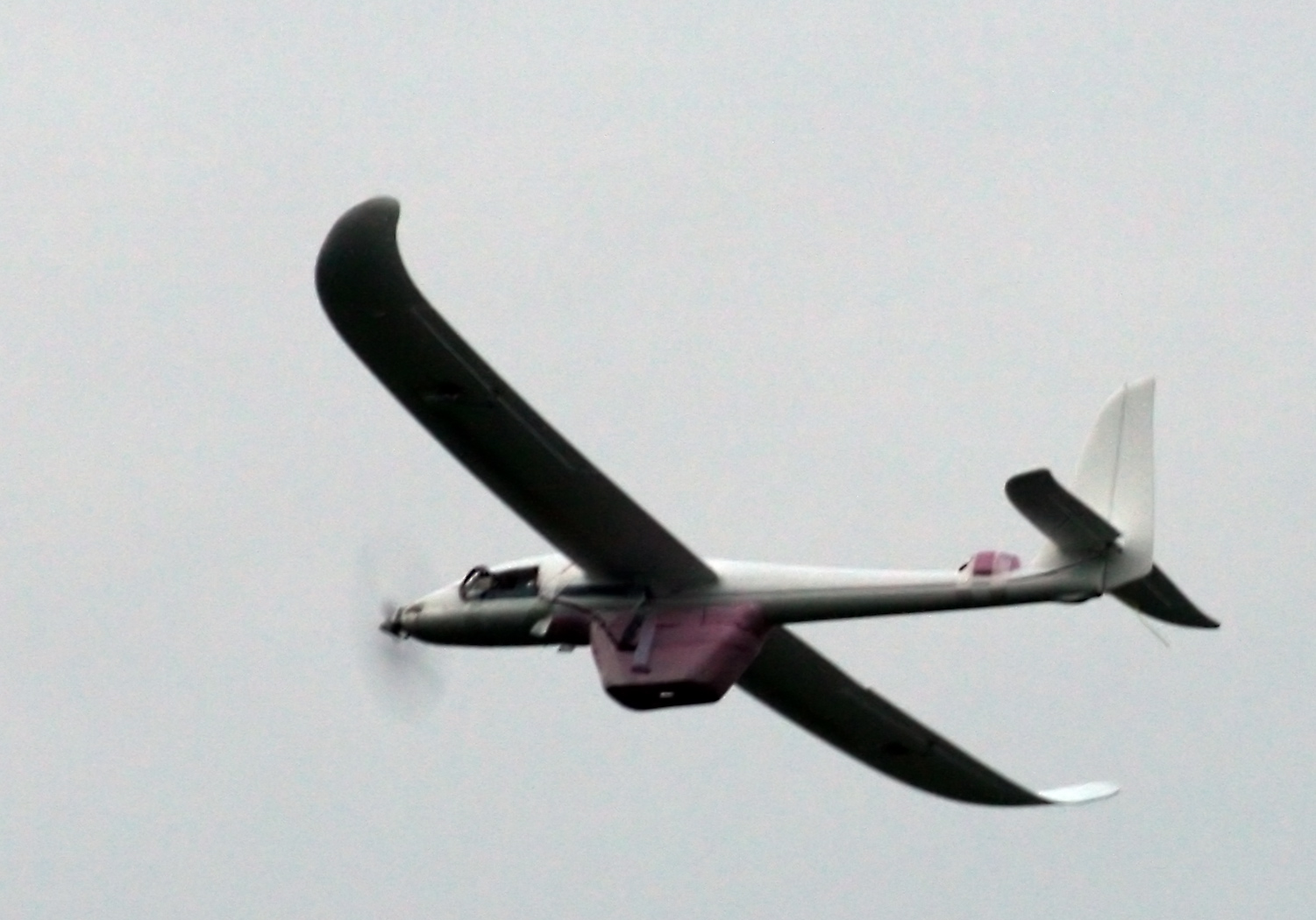
We met with Corben at McAllister Park to fly the project. The conditions were perfect with almost no wind and a clear sky. After getting it all set up, we attempted to do radio check. The servos and speed controller were acting very erratically. It was evident that something was causing interference. We first attempted to replace the radio receiver antenna as the base looked potentially faulty. This did not solve the problem. After connecting the servos and speed controller directly to the radio receiver we found that the PCB was causing the problem. Without it plugged in, the radio system worked correctly. As soon as the board was powered, the servos began glitching. There was no way to deal with the problem on-site, so we decided to just fly it with the board turned off. The plane flew perfectly. The weight added did not impact performance thanks to the addition of the brushless motor. That is at least one less thing to worry about.

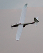
First laden flight
April 23, 2008 (2 hours):
I assembled the plane and photographed it out in the engineering mall. Some of the photos will be used in the remaining homework assignments. I wanted to correct the interference problem with the PCB. I was planning to wrap it in aluminum foil; however, Chuck told me that aluminum would not work very well and that copper would be more appropriate. He found a piece of copper foil and I made a little case out of it to cover both sides of the PCB after first covering all leads with electrical tape. The foil is pretty thick, but shouldn’t be too heavy. I was planning to fly again with Corben; unfortunately, I tested the radio system before leaving and there was still interference. More of the components need to be shielded.


Fully assembled plane.
PCB wrapped with copper foil
April 24, 2008 (1 hour):
Met as a team to divide up the remaining assignments for the project. I took some team photos to include in the final documents. While we were there, we started working on some of the assignments.
April 26, 2008 (4 hours):
I edited my two homework assignments in accordance with the grading comments. I then set out integrating them into the final report. I went through and fixed a lot of formatting mistakes in the report and ensured that the style used was consistent throughout. I added block comments to all of the source code files for the project and then copied them into the report. There were some minor adjustments to catch any lines which wrapped around.
April 27, 2008 (6 hours):
I added my individual contribution into the report and inserted updated software diagrams. After that I did some final editing to it. I uploaded the final copy of the project source code: Team 10 Software v2.5. I effectively remade the poster so that it is actually presentable and aesthetically pleasing. I remade the website for similar reasons after adding more content. I want everything to look good and be useful for future students.
WEEK 16 SUMMARY
Accomplishments: My final technical work for the project involved getting the last of the wiring done on the plane and finishing the physical assembly. I wrote software to log all flight data and attempted a first laden test flight. Unfortunately the PCB caused interference with the radio system which could not be fixed in the remaining time even after adding copper shielding. The second half of the week was spent working on the last parts of documentation for the course.
Weekly Work Total: 25 hours
Project Work Total: 305 hours


