Horizontal Bubbly Two-Phase Flow with Flow Restrictions
Research Supported by the United States Nuclear Regulatory Commission
The nuclear reactor coolant system is composed of various flow geometries and restrictions, including both vertical and horizontal pipes, interconnected with flow restrictions such as elbows and tees. While the knowledge base of two-phase flow regime transition and interfacial area transport in these conditions is quite limited, they play key roles in the pressure drop and heat transfer capability of the fluid.

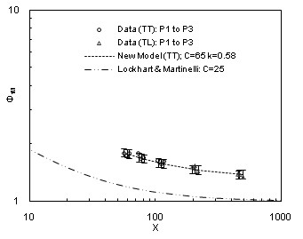
This study performed analysis upon previously acquired data in the horizontal two-phase flow through channels with various flow restrictions, collected at the University of Wisconsin-Milwaukee. The experimental facility, shown in Figure 1 was composed of 50.3 mm ID glass pipes with both a 90° and 45° horizontal elbow installed. To evaluate an interfacial area transport equation for the horizontal bubbly flow, a required pressure drop model that accounted for the two-phase minor loss was developed, and the results shown for the 90° elbow in Figure 2. Finally, a preliminary interfacial area transport equation applicable to horizontal bubbly flow with either a 90° and 45°elbow restriction was developed with some characteristic results shown in Figure 3.

Seungjin Kim
Capt. James McCarthy, Jr. and Cheryl E. McCarthy Head and Professor of Nuclear Engineering
My interests include thermal-hydraulics, reactor safety, two-phase flow experiments and instrumentation, interfacial area tranport modeling.