Solar thermal power generation holds great promise for providing the world with clean, renewable and cost-competitive power on a large scale. Thermal energy storage for solar thermal power plants offers the potential to deliver electricity without fossil fuel backup as well as to meet peak demand, independent of weather fluctuations. This is one of the research focus areas of Professor Suresh V. Garimella, Executive Vice President for Research and Partnerships and R. Eugene and Susie E. Goodson Distinguished Professor of Mechanical Engineering at Purdue University. This work has included collaboration with SolarPACES, Sandia National Labs, National Renewable Energy Labs (NREL), and the Electric Power Research Institute (EPRI).
Some of the projects in his solar thermal research program are described on this page. There are also one-slide summaries describing some current research: slide 1, slide 2, and slide 3. There is a link to an energy text "Understanding the Global Energy Crisis," Coyle and Simmons, 2014, Purdue University Press. It can be accessed via here. Additional details of Dr. Garimella's research are available in the following papers:
|
|
||
|
|
||
|
|
||
| R. A. Simmons, H. Wang, S. V. Garimella, and E. A. Groll, “Hybrid, Plug-in Hybrid, and Electric Vehicle Energy Consumption Sensitivity to the Combined Effects of Driving Cycle and Ambient Temperature-Induced Thermal Loads,” 3rd Sustainable Thermal Energy Management International Conference (SUSTEM 2015), Newcastle upon Tyne, United Kingdom, July 7-8, 2015. | ||
|
|
||
| C. Mira, S. M. Flueckiger and S. V. Garimella, “Numerical Simulation of Single- and Dual-Media Thermocline Tanks for Energy Storage in Concentrating Solar Power Plants,” Solar Power And Chemical Energy Systems, Las Vegas, NV, September 17-20, 2013. | ||
|
|
||
| S. M. Flueckiger, B. D. Iverson, and S. V. Garimella, “Economic Optimization of a Concentrating Solar Power Plant with Molten-salt Thermocline Storage,” ASME Journal of Solar Energy Engineering, Vol. 136, 011016, 2014. | ||
|
|
||
| S.M. Flueckiger, B.D. Iverson and S.V. Garimella, “Simulation of a Concentrating Solar Power Plant with Molten-Salt Thermocline Storage for Optimized Annual Performance,” ASME International Conference on Energy Sustainability, ES2013-19297, Minneapolis, MN, July 14-19, 2013. | ||
|
|
||
|
|
||
|
|
||
| B. J. Woodland, A. Krishna, E. A. Groll, J. E. Braun, W. T. Horton and S. V. Garimella, “Thermodynamic Comparison of Organic Rankine Cycle with Liquid Flooded Expansion and with Solution Circuit,” Heat Powered Cycles Conference 2012, Elkmaar, Netherlands, Sept 10-12, 2012. | ||
| C. Libby, “Solar Thermocline Storage Systems - Preliminary Design Study,” Electric Power Research Institute, June 2010. | ||
|
|
||
|
|
||
|
|
||
| S. Flueckiger, Z. Yang and S.V. Garimella, “Thermocline Energy Storage in the Solar One Power Plant: An Experimentally Validated Thermomechanical Investigation,” ES2011-54578, Proceedings of the ASME 2011 5th International Conference on Energy Sustainability, Washington D.C., August 7-10, 2011. | ||
|
|
||
| Solar Thermocline Storage Systems: Preliminary Design Study. Electric Power Research Institute, Palo Alto, CA: 2010. 1019581. | ||
|
|
||
|
|
||
| Z. Yang and S. V. Garimella, “Melting of Phase Change Materials with Volume Change in Metal Foams,” ASME Journal of Heat Transfer Vol. 132, 062301(1-11), 2010. |
Thermal Energy Storage with Single-Tank Thermoclines
 A
single-tank thermocline storage design (see the
experimental thermocline setup to the left from
Brosseau, D.A., Hlava, P.F., Kelly, M.J., Testing
Thermocline Materials and Molten-Salt Heat Transfer Fluids for
Thermal Energy Storage Systems Used in Parabolic Trough Solar Power
Plants, Sandia Report, SAND2004-3207, 2004.)
can significantly reduce storage costs,
and is one of the most attractive approaches for solar thermal
energy storage. The motivation of such a tank is to retain
excess volumes of both hot and cold heat transfer fluid inside a
single volume simultaneously. The two isothermal regions
remain vertically stratified via buoyancy forces and are separated
by a thin region of large temperature gradient. Energy is added to
the thermocline tank via hot fluid entering the top and cold fluid
exiting the bottom (a charge half-cycle). To recover the
stored energy for power generation, the flow direction is reversed
such that hot fluid exits the top (a discharge half-cycle).
A
single-tank thermocline storage design (see the
experimental thermocline setup to the left from
Brosseau, D.A., Hlava, P.F., Kelly, M.J., Testing
Thermocline Materials and Molten-Salt Heat Transfer Fluids for
Thermal Energy Storage Systems Used in Parabolic Trough Solar Power
Plants, Sandia Report, SAND2004-3207, 2004.)
can significantly reduce storage costs,
and is one of the most attractive approaches for solar thermal
energy storage. The motivation of such a tank is to retain
excess volumes of both hot and cold heat transfer fluid inside a
single volume simultaneously. The two isothermal regions
remain vertically stratified via buoyancy forces and are separated
by a thin region of large temperature gradient. Energy is added to
the thermocline tank via hot fluid entering the top and cold fluid
exiting the bottom (a charge half-cycle). To recover the
stored energy for power generation, the flow direction is reversed
such that hot fluid exits the top (a discharge half-cycle).
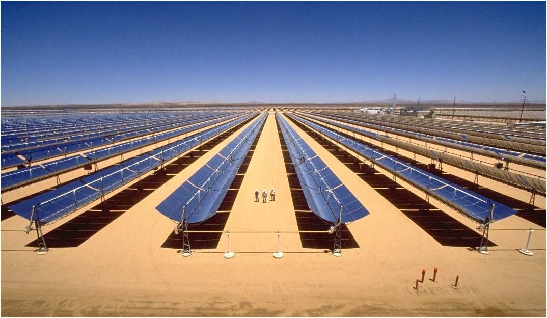
Due to the temperatures associated with concentrated solar power (CSP) plants such as parabolic troughs (as illustrated in the schematic below with a picture of the parabolic trough field from Solar Thermocline Storage Systems: Preliminary Design Study. Electric Power Research Institute, 1019581, Palo Alto, CA: 2010.), the heat transfer fluid is either a synthetic oil or molten salt. Of the two fluids, growing interest is in nitrate molten salts due to the availability for higher operating temperatures to improve plant efficiency, as well as lower material cost relative to oil.
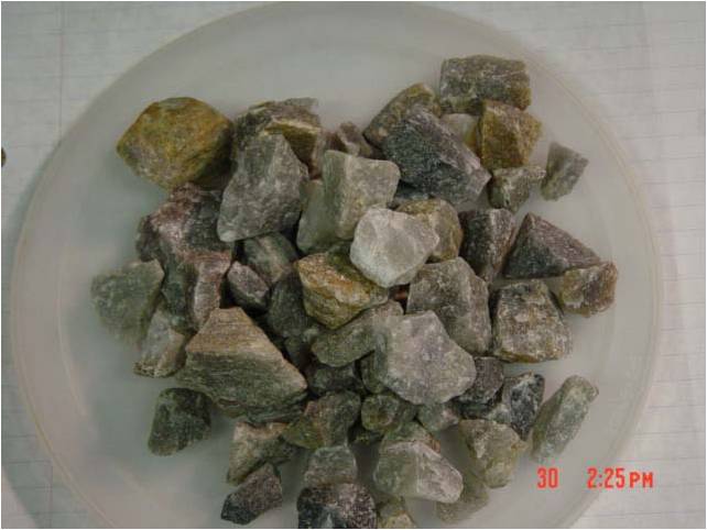
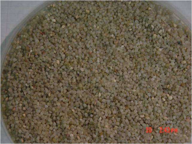
In the thermocline tank, further cost savings are achieved by including a low-cost granulated filler material (quartzite rock and silica sand shown in figures below from Brosseau, D.A., Hlava, P.F., Kelly, M.J., 2004, Testing Thermocline Materials and Molten-Salt Heat Transfer Fluids for Thermal Energy Storage Systems Used in Parabolic Trough Solar Power Plants, Sandia Report, SAND2004-3207.) inside the tank to reduce the required fluid volume and to further inhibit axial conduction detrimental to the thermal stratification.
Simulation of the thermocline tank is performed with the geometry shown in the schematic below. A tank of inner diameter d is filled with a porous bed of quartzite rock of height h.
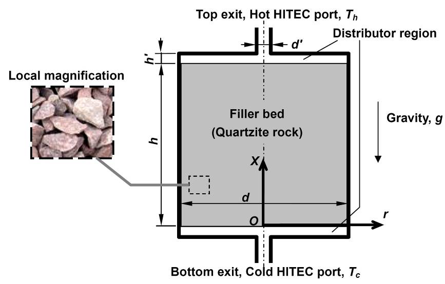
On both the top and bottom of the porous bed are distributor regions free of filler material. These distributor regions serve to maintain a uniform flow condition at both ends of the filler bed in order to achieve good thermal stratification inside the filler bed. Molten salt flows through the filler bed from the top to the bottom of the filler bed in the charge half-cycle, and in the reverse direction during the discharge half-cycle.
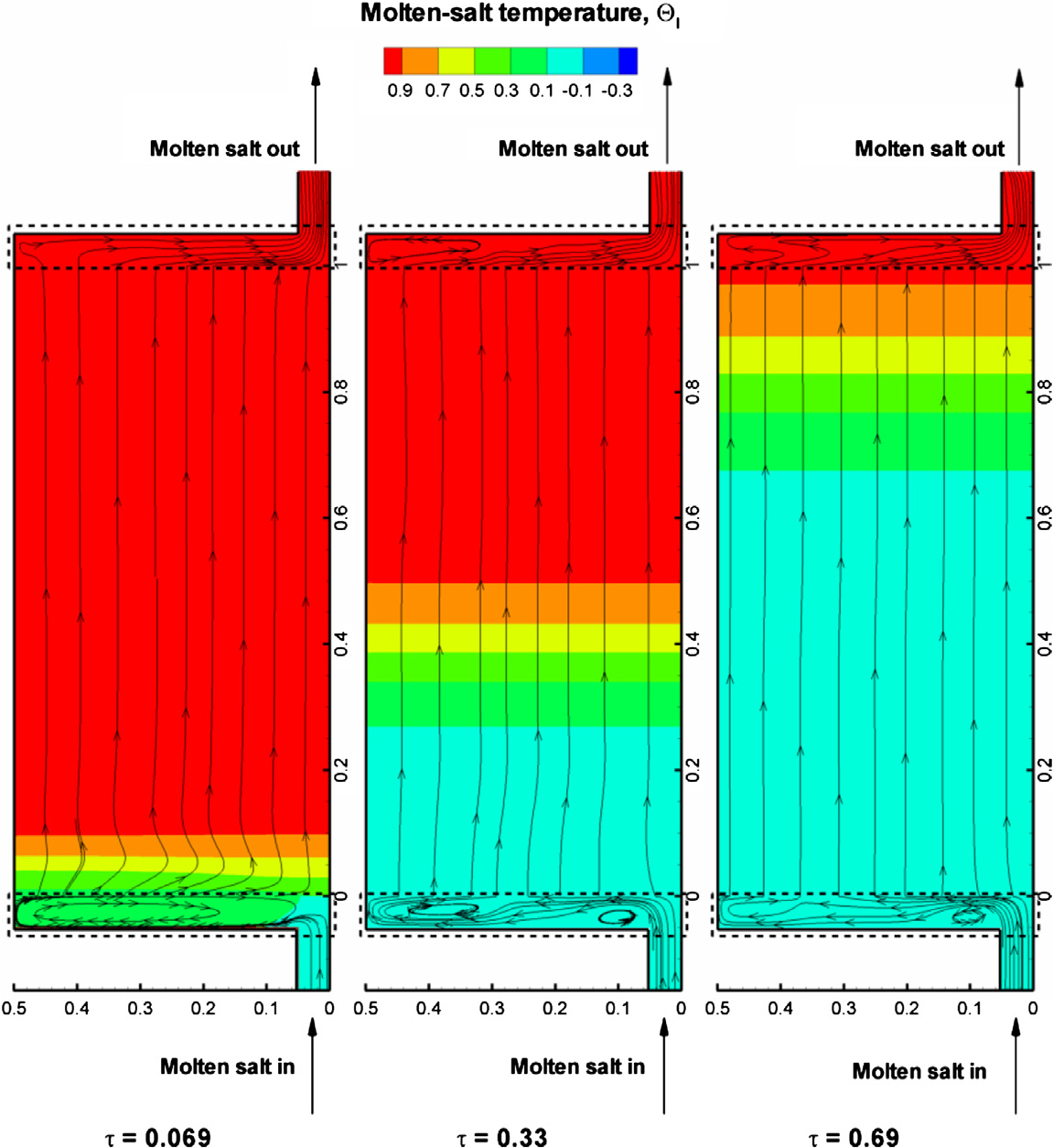
Listed below are one set of parameters of a thermocline tank, for which the temporal variation of the flow streamlines and temperature field during a discharge cycle are computed using a comprehensive two-temperature model as illustrated in the figures. Use of a two-temperature model avoids the assumption of thermal equilibrium between the rock and the salt. Cold molten salt flows through the lower port into the tank, is heated by the rocks and is discharged as hot molten salt from the top port. As the discharge proceeds, the hot region in the tank shrinks.
Molten salt: HITEC (53% KNO3, 40% NaNO2, 7% NaNO3)
Filler Materials: Quartzite rocks (average size of 0.1 m)
High temperature level: 450 °C
Low temperature level: 250 °C
Thermal Power: 500 MW
Only a portion of the thermal energy stored in the tank can be retrieved at a hightemperature level as "useful" energy that can be employed in power generation. The ratio of high-temperature energy output by the tank to that initially stored constitutes an efficiency metric. The discharge efficiency at different discharge powers and total thermal energies is shown below. A high discharge efficiency occurs at a low discharge power and a high total thermal energy.
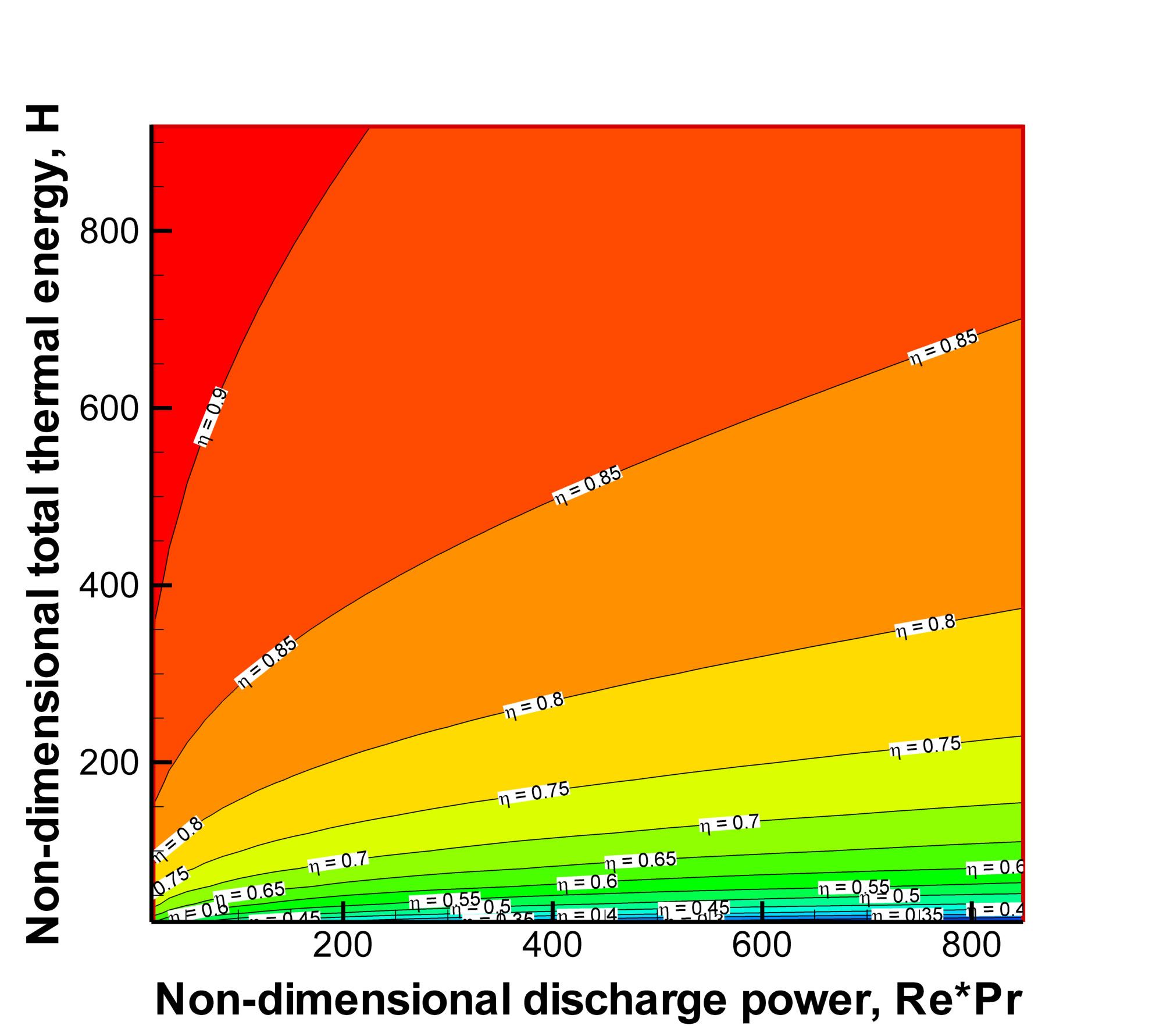
.
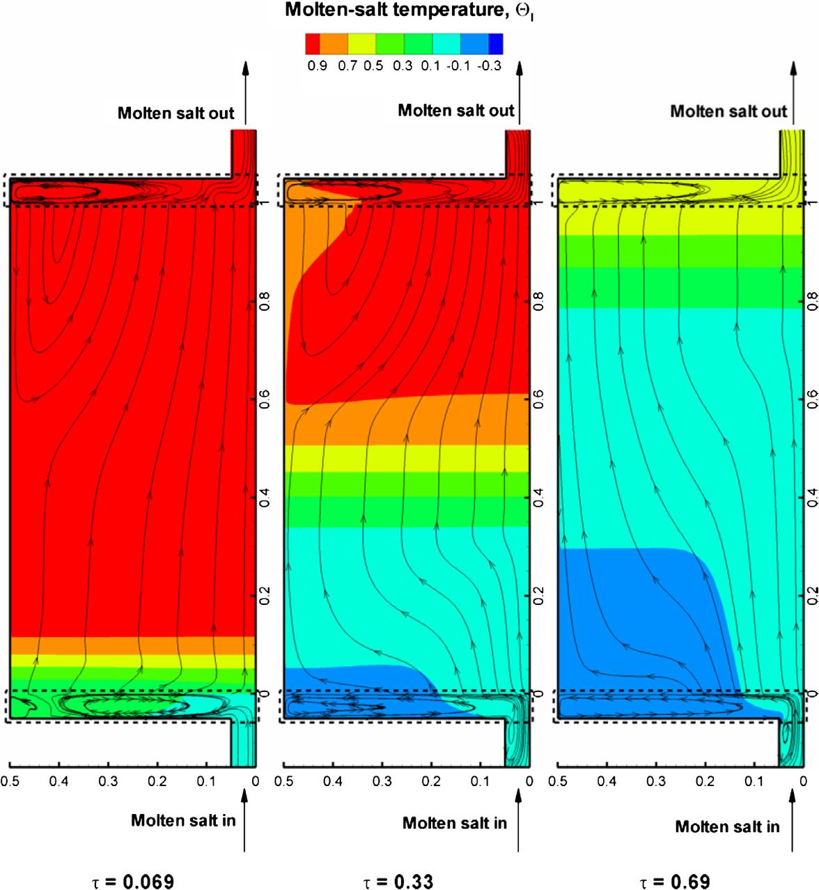
Influence of Environmental Boundary Conditions
The effect of the environmental boundary conditions on the thermocline performance has also been investigated. In the case of heat loss at tanks (when the insulation is not perfect), the following behavior is observed in the upper distributor.
Animation to illustrate vortex shedding in thermocline distributor
39 MB .avi file works well in Quick Time Player or RealPlayer - Provided as supplementary information for "Molten-Salt Thermal Energy Storage in Thermoclines under Different Environmental Boundary Conditions," by Zhen Yang and Suresh V. Garimella (in review with Applied Energy).
Design Procedure for Thermoclines
The goal of thermocline design is to ensure that it is capable of providing the required amount of high-temperature energy at different power levels and durations. The following step-wise procedure can be used for a robust design of thermoclines.
1. Choose tank diameter d and the filler particle size ds, based on practical requirements
2. Calculate the cross-sectional of the storage tank A = 0.25pD2, and then the discharge power per unit cross-sectional area (P / A) and total thermal energy per unit cross-sectional area (Q / A)
3. Calculate the non-dimensional discharge power RePr and useful thermal energy Hh, using Eqs. (1) and (2), respectively
|
|
|
|
|

4. Calculate Re from the value of RePr and assuming H = Hh
5. Using the Re and H obtained in step 4 to calculate h by Eq. (3)
|
|
6. Obtain H by dividing Hh with the efficiency h obtained in step 5
7. Repeat steps 5 and 6, until the difference between the newly obtained H and that in last iteration is smaller than 0.1%
The final H is the required height for the thermocline storage tank, and also obtained is the discharge efficiency h.
The dimensional height of the tank h is calculated by h = ds * H.
Example designs of thermoclines at different powers and durations are shown in the table below.
(Q: Total thermal energy; P: Discharge power; d: Tank diameter; ds: rock size; h: discharge efficiency; h: tank height)
|
Case No. |
Q (MWh) |
P (MW) |
d (m) |
ds (m) |
h (-) |
h (m) |
|
1 |
5 |
1 |
2 |
0.05 |
83.6% |
15.2 |
|
2 |
0.1 |
75.4% |
16.8 |
|||
|
3 |
5 |
0.05 |
73.4% |
2.77 |
||
|
4 |
0.1 |
61.4% |
3.31 |
|||
|
5 |
2 |
2 |
0.05 |
81.6% |
15.6 |
|
|
6 |
0.1 |
72.4% |
17.5 |
|||
|
7 |
5 |
0.05 |
70.5% |
2.88 |
||
|
8 |
0.1 |
57.6% |
3.52 |
|||
|
9 |
10 |
1 |
2 |
0.05 |
88.0% |
28.8 |
|
10 |
0.1 |
81.6% |
31.1 |
|||
|
11 |
5 |
0.05 |
80.1% |
5.07 |
||
|
12 |
0.1 |
70.5% |
5.76 |
|||
|
13 |
2 |
2 |
0.05 |
86.4% |
29.4 |
|
|
14 |
0.1 |
79.1% |
32.1 |
|||
|
15 |
5 |
0.05 |
77.8% |
5.22 |
||
|
16 |
0.1 |
67.3% |
6.03 |
Scaling Performance to Different Power Capacities
The models developed may be readily scaled up or down to different power levels. One example is shown in the table below for various representative thermocline designs with d = h, t0 = 12 h (discharge time) and filler particle diameter ds of 0.1 m.
|
H |
100 MW |
500 MW |
1000 MW |
|||
|
d or h (m) |
h (-) |
d or h (m) |
h (-) |
d or h (m) |
h (-) |
|
|
1.0C0 |
23.0 |
72.4% |
39.3 |
76.1% |
49.6 |
77.3% |
|
1.5C0 |
26.3 |
80.3% |
45.0 |
84.0% |
56.7 |
85.3% |
Thermal Ratcheting in Thermoclines
As the thermocline tank is repeatedly cycled with hot and cold molten salt, both the tank wall and internal filler undergo large fluctuations in temperature. Disparity in the material coefficients of thermal expansion leads to instances of separation and interference at the interface. At separation, an annular gap between the rock and wall is generated by greater expansion of the tank wall, then filled via bed reorientation or slumping. When the tank is then cooled, this slumping prevents the tank wall from returning to its original radius, causing interference and an associated hoop stress in the wall. If this stress is elastic, the tank and rock will reach a structural equilibrium. If however, the hoop stress yields the tank wall, the expansions will accumulate with each cycle until catastrophic failure as the mechanical strain from contraction fails to recover all of the thermal strain associated with expansion. This progressive plastic expansion of the tank wall is a potential failure mode known as thermal ratcheting.
Numerical investigation of thermal ratcheting is performed with a multi-layer thermocline tank wall composed of steel sandwiched by two separate layers of insulation material, shown in the figure below. The quartzite rock bed is assumed to be cohesionless (no resistance to slumping) and perfectly rigid (no mechanical deformation). In this scenario, the hoop stress in the tank steel is directly proportional to the amplitude of temperature variation of the steel.
Thermocline with tank wall composed of steel (2) and insulation (1 and 3) layers.
Multiple charge and discharge half-cycles were performed for a tank 12 m in both height and diameter, for various individual wall layer thicknesses and external loss conditions to the surroundings. The cases are summarized in the table below with results (normalized with respect to yield strength) plotted in the following figure. As seen, increasing the thickness of the internal insulation layer reduces the potential for thermal ratcheting by reducing the temperature fluctuations experienced in the steel.
|
Case |
h (W/m2 K) |
ε |
δ1(cm) |
δ2(cm) |
δ3(cm) |
|
1 |
5 |
1 |
0.1 |
0.2 |
0.05 |
|
2 |
10 |
1 |
0.1 |
0.2 |
0.05 |
|
3 |
5 |
0.5 |
0.1 |
0.2 |
0.05 |
|
4 |
10 |
0.5 |
0.1 |
0.2 |
0.05 |
|
5 |
5 |
1 |
0.2 |
0.2 |
0.05 |
|
6 |
5 |
1 |
0.1 |
0.4 |
0.05 |
|
7 |
5 |
1 |
0.1 |
0.2 |
0.025 |