Lab 5b Tips: DC Brush Motor
Pre-lab
- Do not use Laplace transforms!
- The entire pre-lab should be completed with algebraic manipulation of equations (1-4) and the following trigonometry identity where α = tan-1(b/a).

- You can safely assume φ = -α.
- You may verify your expressions numerically using the constant parameters below. Note: J is needed to calculate A and vice versa.
      ra = 2;       % Ohms


      Laa = 4e-3;   % H


      kt = 0.037;   % Nm/A


      kv = 0.039;   % Vs/rad


      J = 5e-5;     % Nms^s/rad


      Bm = 7e-5;    % Nms/rad


      K1 = 10;      % V


      K2 = 5;       % V


      we = 2*pi*10; % rad/s
- Using these parameters, the correct numeric results are
ωro = 233.7 rad/s
A = 28.55 rad/s
J = 5x10⁻⁵ Nms2/rad
In-lab
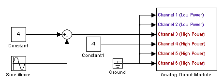
- You can complete the entire lab with this one model.
- See Recall Factory Setup
- See AC Coupling Mode
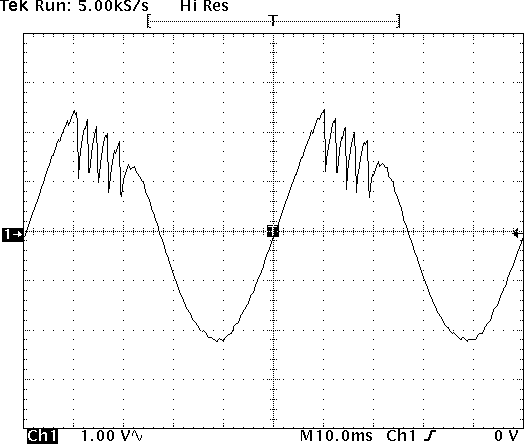
- If you are experiencing amplifier overloading, the supplied current waveform will have fold back. A typical example of current fold back is shown below.
- See Average(#) Mode
- Remeber we only measured the friction in motor 1. To account for motor 2, double the measured Bm in the calculations and simulation.
- See Single Trigger Mode. Note: The oscilliscope must be in DC coupling and either sample or hi-res acquisition mode for single trigger mode to work properly. It is easiest to recall factory setup before setting single trigger mode to correct these settings.
- See Paired Cursors
- Alternatively, the following Matlab code may be used to find the time constant of the exponential speed response. Once you have saved data from 'digscope', create an m-file to load the data such as:
      load oscope_0_4.dat


      t = oscope_0_4(:,1);        % s


      v = oscope_0_4(:,2);        % V


      wr = oscope_0_4(:,3)/k_vt;  % rad/s


      Ia = oscope_0_4(:,4);       % A


      wr_ss_0_4 = max(wr);        % rad/s


      tm_0_4 = find_tm(t,v,wr);   % s
Then re-create the 'find_tm' function below in a separate m-file.
      function delta_t = find_tm(t,v,wr)


      wr_stop = (max(wr)-min(wr))*(1-exp(-1)) + min(wr);


      t_start = t(find(v>v(1)+2,1));


      t_stop = t(find(wr>wr_stop,1));


      delta_t = t_stop-t_start;
Check your work.
- Javg ≈ 8e-5 Nms2/rad
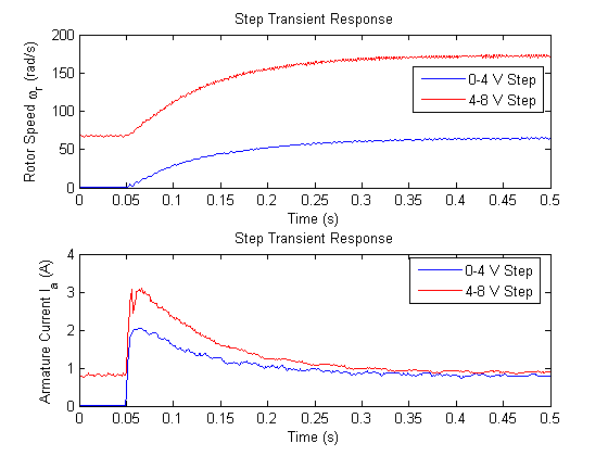
- ωr,ss ≈ 85 rad/s (simulated), 70 rad/s (0-4 V), or 175 rad/s (4-8 V)
- τm ≈ 90 ms
- Sample speed and current transient response.
Post-lab
- For question 1, your plot of measured Te will not align well with your predicted values because what we measured was not actually Te. What we actually measured was the torque supplied by motor 1 which is equal to Te - Bmωr (Te - friction). You can correct your results by adding the frictional term into to your measured values. If you want even better results, reexamine the torque vs. speed data from lab 5a and try improving your approximation for Bm.
- For question 2, consider the difference between the electrical time constant τe (you will need to calculate this) and the mechanical time constant τm that you measured in lab.