
|
|||
|
Former post-doctoral and visiting scholars Image formation and processing group Recent conference presentations
|
FastAnt--An Antenna Simulation SoftwareFastAnt is an antenna simulation software for simulating complex antennas on a large platform such as a car [1,2]. It can simulate complex structures such as a microstrip antenna with radome, housing etc when it is mounted on an automobile. It can simulate up to 500,000 unknowns on a PC computer with 3.5 GB of RAM. More recently, a parallel version of FastAnt is able to solve up to 3 million unknowns on a simple cluster [3]. FastAnt solves the radiation problem using integral equations. It uses currents as unknowns. Often times, currents only reside on the surface of a scatterer. Hence, the number of unknowns is usually much smaller than those of differential equation solvers when a problem of the same electrical size is solved. Such integral equations are first converted to a matrix equation using the method of moments (MOM). The matrix equation is fully populated and is difficult and expensive to solve and store when the number of unknowns becomes large. However, FastAnt uses the multilevel fast multipole algorithm (MLFMA) to accelerate the matrix-vector product of the matrix equation. Hence, when used together with an iterative solver such as the conjugate gradient (CG) method, FastAnt can solve problems orders of magnitude faster than the traditional methods of solving matrix equations resulting from MOM.
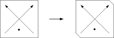
The simulation indicates a circularly polarized (CP) field generated by a microstrip patch antenna. One can see the swirling of the current produced by the CP microstrip patch. The CP microstrip patch is designed according to a theory outlined by the late Prof. Y.T. Lo of EM Lab at the University of Illinois. It consists of a square patch antenna. The symmetry of the patch is destroyed by clipping the NE and SW corners of the square patch. This causes the two degenerate modes of the patch to split into two non-degenerate modes (see figure below). 
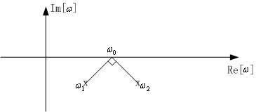
These two non-degenerate modes then give rise to two poles in the system function of the antenna. Due to radiation damping, the two poles are slightly below the real axis on the complex omega plane (assuming exp(-i*omega*t) time dependence). The Q of the antenna due to radiation damping can be estimated easily, and hence, the distance of the poles from the real axis. The separation of the two poles can be adjusted by the amount of asymmetry introduced by clipping. The system function of the microstrip antenna can be gotten from a two-mode approximation (system theorist will say two-pole approximation). 
In the above, x and y indicate the two directions of the two orthogonal currents on the cleaved square patch. By picking the operating frequency to be in between the two poles, and adjusting the separation of the two poles, the two modes can be excited to be 90degrees out of phase. Also, the location of the probe can be judiciously chosen so that the two modes are equal amplitude. Hence, a CP microstrip patch antenna can be designed as such. 
References:
|