
Progress Reports for John Busch Jr.
Weeks 1 - 2:
Date: 1/22/16Total hours: 10
Description of design efforts:
My efforts in the first week of this project focused on fully specifying the intent of our design along with the rest of the team. Through brainstorming each team member formed their own mental image of how the device would operate and it was critical that we discuss and finalize the goal we hope to achieve. Five Project Specific Success Criteria (PSSC) were developed to define what the team believed to be the core operation of this project. In our discussion I contributed former robotics knowledge to best tailor the PSSCs to put emphasis on the electrical design of our system to showcase the skills team members have developed during their education.
These PSSCs as well as an initial design budget are documented in our final project proposal. The budget is based on rough cost estimates of raw 3D printing materials, commonly available servo motors, and Firgelli linear actuators.
In the second week the team worked together to form a state diagram of the device from the user’s point-of-view, shown in Figure 1.1. Operation was defined from device power on to full operation, including necessary prompts to the user and how the mechanical components should respond to convey meaning to the user. I was able to provide feedback on what hardware would be used in the final user interface design and annotated the initial state diagram on the board for Catie to digitize in Microsoft Vizio. The team collaborated to determine three distinct modes of operation for the project: demo, record & play, and quiz. These modes correspond to different stages of the learning process and provide a path for the user to ramp up their learning of AMA.

Hardware specifications were also flushed out this week in addition to software. Shown in Figure 1.2 is a preliminary hardware interface diagram specifying the desired protocols used between major functional components of the project. This will greatly assist in determining what modules the microcontrollers must utilize and provide perspective into where large amounts of power will be used. In this task I helped to determine what communications protocols would likely be available and to what extent components could be daisy chained.

After back and forth discussion with Dave we were able to well specify the theory of the devices operation as described in our functional specification. My research into electromechanical components for the project also contributed to the power and temperature constraints described in the document.
As I have primary access to a 3D printer, I will be in charge of designing both the PCBs as well as the CAD models for the robotic hand itself. All designs will be uploaded at key points in their progress.
Week 3:
Date: 1/29/16Total hours: 8
Description of design efforts:
I spent a great deal of time this week researching components and applying constraints to find suitable parts for our project. Our design has need of two microcontrollers – one for the base (the “master microcontroller”) and another for the hand (the “hand microcontroller”). From previous experience I believe Atmel’s IDE Atmel Studio is one of the strongest free IDEs available. Given Atmel’s wide variety of microprocessors available, we began by constraining ourselves to Atmel parts. Using their parametric part picker the search was quickly narrowed down to two families: the SAM D21 series and the ATxmega A series.

The top processors in each family (the SAMD21J18 and the ATxmega256A3BU, respectively) have several similar characteristics but with a few defining differences as detailed in Table 2.1. The most major of these differences in regards to the master microcontroller are the ability to simulate the chip in Atmel Studio and the presence of an embedded USB host. As we hope to extend the UI of our design with a USB keyboard, an embedded host allows for very few hardware changes to be made in order to connect the peripheral. Full software simulation also allows for each team member to work individually without needing a hardware testbed. Simulation support is such a strong factor that we decided on the ATxmega256A3BU and modified the hardware diagram in Figure 2.1 to include a USB to SPI chip.

Design constraints surrounding the mechanical hand imposed different limitations on the hand microcontroller. In the current design nine servo motors and five linear actuators drive the hand, meaning the chip must be able to generate nine unique PWM waves simultaneously as well as read from five analog inputs. After returning to Atmel and searching through parts once more, the same two candidates that we examined for the master microcontroller seemed like good fits for this role as well. Each sports several PWM channels and while they may operate at 3.3V, servo motors can be controlled by any signal > 3.0V. The major difference in families in this case is the presence of EEPROM in the ATxmega A series. With EEPROM, constants and parameters can easily be flashed to the microcontroller without needing to fully recompile the code and will make fine-tuning the device go much faster. Choosing the ATxmega256A3BU as the hand microcontroller not only allows us to have EEPROM constants, but it also means we only need to learn AVR assembly for optimizing critical functions rather than both AVR and ARM.
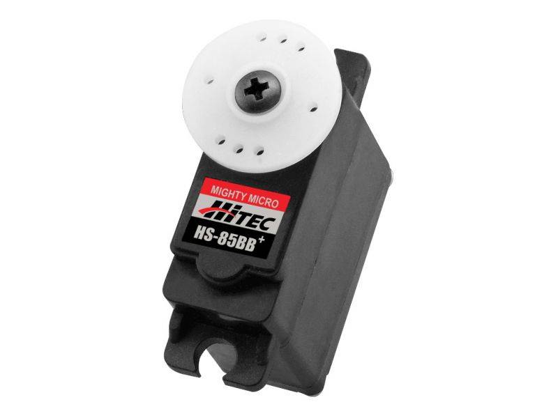
My research this week continued with examining servo motors for use in the curling action of the robotic fingers. RobotShop was a great resource in finding simple servo motors in various sizes. I examined several servos including the HS-485HB, HS-85BB, and Futaba S3114 to determine which can curl a robotic finger most effectively. The final mechanical methods through which the finger will curl are not yet finalized, but in my initial research I found resources related to the design of tendon-driven robotic fingers like this article from IEEE. With this in mind I decided to move forward and prototype with the HS-85BB as it has a smaller form factor to allow for better component arrangement on the hand while still retaining a respectable amount of torque that will compensate for losses in the tendon.
This week I was also able to help in researching and purchasing the 3D filament that will make up our project. Discussion with 3D printing veterans led me to use PLA filament for our design as it prints at a lower temperature and thus has a lower likelihood of warping during printing. ABS was also considered for its unique ability to be welded together using acetone, but the modules of our design will be much smaller than the printing volume of the LulzBot TAZ 5 printer so welding will not be necessary.
In the coming week I plan to CAD a first draft of a robotic finger for prototyping once the PLA filament arrives. PCB footprints will also be made for the ATxmega256A3BU and preliminary Eagle schematics will be created.
Week 4:
Date: 2/5/16Total hours: 10
Description of design efforts:
I spent most of this week preparing the software development environment and prototype hardware for use by the rest of the team. The Atmel Studio solution for our design includes two projects targeting the ATxmega256A3BU, one for the ‘master’ microcontroller and one for the ‘hand’ microcontroller. These can be compiled and flashed to chips independently. Our prototype hardware for the Atmel STK600 development kit also arrived this week, allowing us to create a testbed shown in Figure 3.1.

I also wrote code this week to serve as both an intro to the Atmel Studio environment for other team members and as a test of programming the chips. Reading through the ATxmega Manual I found the necessary registers to configure pin 2 on Port A to fire as an active-low asynchronous interrupt as shown in Figure 3.2. Following updating the AVR Dragon firmware, we compiled the program and flashed it to the ATxmega over JTAG for active debugging. The pin correctly measured 3.3V, showing that the internal pull-up resistor was enabled. Connecting the pin to a switch and producing a momentary contact closure to ground caused the program to jump to the ISR and hit a breakpoint to notify us as intended. This program will serve as a good jumping-off point for Catie, Dave, and Lauren as the software will be predominantly interrupt-driven.

This week I also discussed how our design would be powered with Dave. We realized the electromechanical components will require a large amount of DC current, and the price of board-mounted and wall-plugged supplies were quite expensive. Following advice from course instructors, we researched ATX power supplies and quickly chose the Lepa MX-F1 N350-SB to serve power to the project. ATX supplies produce all voltages needed in our design (3.3V, 5V, 12V) with a very high wealth of current all within a very affordable budget. Dave and I chose several other parts this week including an I2C level shifter, isolation buffers for the PWM waves, and MOSFETS to finish a preliminary BOM.
I unfortunately was not able to create initial CAD designs and Eagle parts this week due to a high workload outside of the class, but I intend to take some time over the weekend to begin those endeavors. With the mechanical design homework due next week, I will be discussing the packaging with the team to determine how the 3D-printed front panel that houses the buttons, encoder, and LCD will look. Ideally I will print the first revision of the UI and have it nominally functioning by the design review.
Week 5:
Date: 2/12/16Total hours: 15
Description of design efforts:
This week I focused my time primarily on preparing the Eagle library for the PCBs. I hope to have the PCBs done early and sent out for fabrication as soon as possible to give Catie, Dave, and Lauren as much time with the actual hardware as possible. Footprints of the ATxmega256A3BU and the MAX3412E are found in Figures 4.1 and 4.2. I took the ATxmega256A3BU TQFP64 footprint from the Eagle ref-packages library while I fully custom-made the MAXIM21-0110 footprint as per the design in the datasheet.


Preliminary sketches of the layouts for the PCBs were also made, shown in Figures 4.3 and 4.4. In laying out the hand PCB I will have to keep in mind the three voltage levels present on the board as well as the presence of analog signals coming from the linear actuators. This board will greatly resemble a COTS motor driver board in a slightly larger form factor in order to support the large number of electromechanical devices and the 24-pin ATX power connector. The master PCB is mounted on the right hand side of the project enclosure to allow access to the board-mounted USB and SD card slots. It also contains a crystal oscillator that must kept away from traces and have no ground plane beneath it to avoid coupling the high frequency signal to nearby communication channels.


I also worked on the mechanical design of the project including its packaging and materials, detailed in the mechanical overview and shown in Figure 4.5. We intend to 3D print the sloped front panel to present a nice, crisp user interface. We will also print a bracket to attach the LED matrix to the left side of the enclosure. The remainder of the packaging is black acrylic sheets cut to shape and either bolted or hot-glued together. The right panel is detachable for servicing the project. We plan to use roughly 0.5” standoffs to mount the PCBs inside the casing. Rubber no-slip feet attached to the bottom of the enclosure will allow the device to sit comfortably on a desktop with no fear of it sliding off.

Week 6:
Date: 2/19/16Total hours: 12
Description of design efforts:
This week I worked heavily on adding parts for the project to our Eagle library. While the TQFP64, SOT-3, and SOT-5 footprints came from the standard Eagle library, ref-packages.lbr, most others were custom-made from data sheet specifications as in Figure 5.1 with the Molex MiniFit Jr connector for the ATX power supply.


The most intricate layouts were the SD card slot and USB port shown in Figures 5.2 and 5.3, respectively. Using CAD drawings I was able to adequately lay out the footprint to match the physical component as shown in Figure 5.4.

Additionally I worked on initial schematics for the base and hand PCBs this week. Shown in Figure 5.5 is the H-bridge circuit used for driving our Firgelli linear actuators. The actuators take 12V across the two leads and the direction of the potential difference determines whether the actuator extends or retracts. Each actuator will have a 2-N 2-P H-bridge circuit (the DMHC3025LSD) driving it. A complementary NMOS circuit allows the microcontroller to interface with the H-bridge. A low GPIO signal will shut off the FET and drive the lead of the linear actuator to 12V through the pull-up resistor. A high GPIO signal will enable the FET and pull the lead low to ground. We chose the 2N7002P NMOS for the job due to its cheap price as the driver FET will not drive a large amount of current and can have a higher RDSon.

Figure 5.6 shows the front panel interfacing circuitry. The supporting capacitors and pull-up resistors are for the rotary encoder and are laid out as described in its datasheet. A harness with wires soldered directly to component leads and terminating in either female 0.1” headers or a ribbon cable with a press-fit 0.1” connector will connect the front panel devices to the board. This setup allows the front panel to be easily removed for maintenance.

Multiple ISO7230C isolation buffers are laid out in Figure 5.7 with supporting bypass capacitors to isolate the PWM signals to the servo motors as well as shift the logic level from 3.3V to 5V. Most servos can take a PWM signal between 3V and 6V for control so a direct 3.3V PWM wave suffices for control. However, we were concerned about a short occurring within the servo and potentially shorting the PWM line to ground or 5V and damaging the microcontroller, thus we elected to use an isolator chip to buffer the PWM signal.

Week 7:
Date: 2/26/16Total hours: 11
Description of design efforts:
The majority of my work this week revolved around the PCB designs in Eagle CAD. Designs are nearing completion for next week’s design review, so early this week I finalized some of off-board connectors we will be using. We will use ribbon cables with insulator-displacement connectors (IDCs), shown in Figure 6.1, to link the hand and master boards. The finalized front panel hosting the push buttons and rotary encoder will be attached using a similar connector. Currently we plan to use standard 0.1” connectors for attaching the linear actuators and servos to the hand board.

I also finalized the schematics this week, shown below in Figures 6.2 and 6.3. Debug signals and test points may be added between now and fabrication, but the critical systems are all present and accounted for.


Figure 6.4 shows the current layout of the hand PCB. Three main sections make up the board: the power supply and interconnects on the bottom, the servo drivers in the top right, and the linear actuator drivers in the top left. These three sections share a common ground plane on the top copper with 3.3V, 5V, and 12V power planes on the bottom copper in each respective section. Routing is not yet complete on the microcontroller, but individual sub-circuits can be seen in Figures 6.5 and 6.6. I will correct silk screen overlaps before fabrication. Initial placement with size 1206 passives left little room for traces to pass each other comfortably around the microcontroller and other ICs. Due to my previous experience soldering 0603 package passives, I elected to use those for our design to save space and allow for more efficient trace routing.


My schedule this week unfortunately kept me from getting the master PCB to the same level of completion as the hand, but Figure 6.7 shows the initial parts placement. I was also unable to CAD up the front panel design for printing. I plan to use this weekend to complete both of these tasks and, pending printer availability, have the initial front panel design printed in PLA for the design review next Thursday.

Week 9:
Date: 3/11/16Total hours: 14
Description of design efforts:
Following the midterm design review I incorporated feedback into the PCB schematics and layouts. To allow for future debugging and extension of functionality, I broke out four spare GPIO pins on the master board and two on the hand board. I also increased isolation distance on all flood fills to 12mil from the Eagle default of roughly 6mil. Figures 7.1 and 7.2 show the final schematics with their corresponding layouts in Figures 7.3 and 7.4.


I generated Gerber files using the Eagle CAM processor, verified them on CircuitPeople, and uploaded them to OSHPark for final visual inspection created by their rendering engine. Figures 7.5 through 7.8 are the renders generated by OSHPark.


Once our last Digikey order arrived, I verified all part footprints against a 1:1 printout of the top copper of each board shown in Figures 7.9 and 7.10. Between the two images every unique footprint is verified against a representative part. I took the Panasonic size C and D electrolytic capacitor footprints from the SparkFun Eagle library, but unfortunately the pad lengths on them is a bit short for hand soldering. I noticed this after placing the order to OSHPark and should still be able to solder the capacitors given a bit of patience, but if a hardware revision occurs I will lengthen these pads. In the worst case I will scrape away some of the soldermask to effectively lengthen the pad.


Over spring break I intend to create and print the first prototype of a robotic finger for the middle, ring, and pinky fingers. We currently have one of linear actuators and one of the servos available so initial prototyping will allow us to determine if these components have the necessary torque to drive our design.
Week 10-11:
Date: 3/25/2016Total hours: 26
Description of design efforts:
Over Spring Break I worked to design and fabricate a single finger of the robotic hand to test the limits of the Firgleli linear actuators and to see what 3D printing tolerances were acceptable. Figure 8.1 shows measurements and analysis of my own finger to dimension out the design. Our design decouples the curling motion and the right angle motion of the finger into two different mechanisms due to the intricacy of the American Manual Alphabet. I based the method of curling the finger on the design used by the OpenBionics Ada v1.0 Hand in which an electromechanical device pulls on a tendon wire routed through the phalanges of the finger. The Ada hand is made of a rubber-like material called NinjaFlex that allows it to naturally return to its original shape while our hand is composed of PLA and will have a rubber band mounted on the back of each finger to tension it back from curling. A linear actuator imparts the right angle motion by causing the proximal phalange to rotate about the knuckle joint by moving in a 1cm radius arc about the central pin at that join (shown in Figure 8.2).


I assembled the finger following printing and examined the parts for manufacturing defects. Despite the 3.5mm diameter in the CAD files, the joints in the phalanges have a horizontal diameter of as low as 2.8mm in some locations due to a lack of support on the material on that side. Vertical diameter is roughly 3.1-3.3mm which is within the expected tolerance for the printer and does not impede a M3 screw or pin from passing through the hole. I plan to edit the CAD files to add additional tolerance on the hole diameters. Luckily, the hole routed through each phalange for the tendon wire was well sized except for the tip of the distil phalange. To correct this I will widen the hole near the fingertip. Motion of the finger can be seen in Figure 8.3.
Our PCBs also arrived at the end of Spring Break, so I took several hours to solder them together on Monday. I attached the ATX power supply to the hand board and applied power, only to be met with a flash and smoke. While the ATX power supply turned on in response to the circuitry on our board, an H-bridge burnt out. After turning off power and examining the damaged circuit with the DMM, the trench MOSTFET’s source and drain appeared shorted. Assuming this to be what had caused the damage, I de-soldered the H-bridge and energized the circuit again, but another H bridge blew out after a few seconds of sustained power. Now convinced there was a flaw in the circuit I salvaged the three working H-bridges and began to analyze the voltages active on the board. The control signals into the H-bridge that should only ever be 0V or 12V had values including 0.5V, 3V, 7V, 8V, and 11V. If a steady voltage between 2V and 10V is applied to the H-bridge, shoot-through will occur as both the P and N channel MOSFETS will open. I then realized the ATxmega had not been programmed and placed its GPIO pins in Hi-Z state by default, meaning the trench MOSTFET was biasing randomly and feeding these obscure voltages to the H-bridges. The design flaw here was a lack of pull-down resistors on the gate of the trench MOSFET, as exhibited by Figure 8.4. We ordered several small package, through-hole 10k resistor to attach to the vias near each NMOS and pull down each gate signal to ground. This will allow the design to fail safe no matter the status of the microcontroller.


The master PCB, on the other hand, worked without a hitch on first boot. Catie and Lauren have begun integration with PCB and have shown the software to work with LCD, LED matrix, SD card, and contact closures to ground.

At the end of the week I worked with Dave to finalize the enclosure design and select parts on McMaster-Carr for assembling our design. I also selected slotted spring pins that will function as hinges on the robotic hand. Along with this order we plan to purchase the remaining linear actuators and servo motors now that we have confidence in their output torque on a prototype system.
Week 12:
Date: 4/1/2016Total hours: 15
Description of design efforts:
At the start of this week I applied the hot-fix for the linear actuator driver circuit discussed in my progress report last week. I soldered pull-down resistors to the gate of each NMOS and verified connections with a DMM. Following the success of three of the H-bridge circuits, I soldered the remaining two in one pass only to have them blow in a similar fashion to the pre-fix chips. DMM analysis of the pads showed no differences to the other three successful circuits. After Dave and I agreed that we were unable to find any defects, we soldered another H-bridge to one of the defective pads only to find it worked perfectly. The only conclusion we have been able to draw at this time is that the two H-bridges that blew after the hot-fix were due to an overabundance of flux still present on the board. After several hours of burn-in time, the hand board is operating as intended.
I dove back into software this week again to verify and test PWM control over spare servo motors in the lab. The driving factor behind our choice of the ATxmega256A3BU was its ability to split the 4-channel, 16-bit TCC0 timer module into an 8-channel, 8-bit timer module. The Hitec HS-85BB+ servo we are using expects a PWM pulse with a period of 20msec and pulse length of 1.9msec for a neutral position. The maximum clock pre-scalar to the TCC modules is 1024, meaning with a 32MHz peripheral clock and 8-bit counter the minimum frequency obtainable is 122.5Hz, or a period of 8.16msec. Taking the peripheral clock down to 16MHz for the entire system allows a period of 16.32msec. While the pulse length to the servo is a rigid quantity and small fluctuations affect the servo’s position, the period is flexible and dropping just under 4msec from the down time did not show negative effects on performance using a waveform generator. With this configuration, the servo can be rotated to 28 different positions ranging from 0 to 180 degrees, or roughly 6.4 degree resolution.

After programming the microcontroller with this configuration, the oscilloscope showed a period that was 16 times longer than expected. This bug was also representative of a problem Lauren met working with the timer module for the quiz mode. Looking once again at the peripheral clock pre-scalar registers, I encountered the system clock control registers. By default, the ATxmega256A3BU resets using the 2MHz internal oscillator rather than the internal 32MHz crystal. The code shown in Figure 9.2 shows proper configuration of the device, setting the peripheral clock pre-scalar, enabling the 32MHz crystal, then setting it as system clock after it is stable. After these changes, the PWM channels displayed the proper 16.32msec period. All clock speed calculations across our project have always been done assuming a 32MHz system clock, so no module configurations need changing as they should now operate as originally intended.

This week we also ordered the nine Hitec HS-85BB servo motors we will be using on the hand as well as the Hitec Pulley 56314 . Given a diameter of 1.456”, we expect this pulley to allow at least 1.114” of tendon retraction if the servo only has a 90 degree throw. Mechanical modification of the servos may allow them to have a 180 degree throw and double the retraction possible.

I was unable to make needed changes to the robotic fingers this week due to a large portion of my time being spent on the Reliability and Safety Analysis homework and my laptop mouse breaking. Dave has leant me his mouse in the meantime and I will be attempting to makes changes and print the middle, ring, and pinky fingers over the weekend.
Week 13:
Date: 4/8/2016Total hours: 13
Description of design efforts:
This week I primarily worked on mechanical revisioning of the robotic hand. Following printing this weekend, I assembled the three-finger palm shown in Figure 10.1. The Firgelli PQ12 linear actuator seated nicely and still produced the 90 degree angular motion desired. My changes to the printing orientation and adding a divot in the fingertip allowed me to route the tendon wire through all parts with ease.

There is a 3mm slotted spring pin at each finger joint to hold the fingers together. Unfortunately, I designed the parts with the same hole diameter at the joints, so there is an excess of friction in the finger curling motion. I placed hooks and guides on each phalange piece for to hold a rubber band in tension and allow the finger to return to its straight resting position. In this version, the hooks and guides are too wide and the rubber band can get caught in the joints.

Figure 10.2 shows fixes to the aforementioned mechanical defects. The inner diameters are 0.5mm larger than the outer joint diameters which should greatly reduce friction in the curling action of the finger. I added chamfers to right-angle protrusions to reduce mechanical stress. The tension string hole was also raised higher up at each joint to reduce the amount of wire retracted by the servo motors when curling the fingers. Right angles have also been added at each joint to stop the fingers from bending back considerably farther than straight (just like an actual human hand).
Our HS-85BB servos also arrived this week. Preliminary testing on the waveform generator shows they have a full 180 degree range of motion as desired and significant torque while only drawing 250-300mA at stall. I am optimistic that they will be able to retract the fingers after the next print removes friction from the joints. Dave is currently working on the mounting and tilting mechanism for the forefinger of the hand. Once he is content with his design, I will integrate it with my changes and have it printed this weekend.
Week 14:
Date: 4/15/2016Total hours: 15
Description of design efforts:
As the project starts coming together, this week was spent printing, assembling, and testing a full mechanical hand. I received the metacarpal CAD files from Dave and mirrored my changes to the knuckle hinge onto them. I also worked with Dave to simplify the geometry for mounting the servo motors to a level the 3D printer could accomplish. STL files were generated and laid out as closely as possible in Cura before being printed as shown in Figure 11.1.

The latest hand was printed in blue PLA plastic to make it stand out from the black enclosure. Changes to the hinges worked very well and the slotted spring pins allowed for very smooth motion. There were some friction problems between the distal and intermediate phalange pieces, but a light sanding fixed that. Future prints will have a bit more tolerance on that joint. Support material came off cleaner than ever before, leaving expected discoloration but very little residue. The final assembled hand can be seen in Figure 11.2.

Unfortunately another H bridge blew this week for much less clear reasons than before. Testing revealed that the ATX power supply would kill itself upon issuing the linear actuators to hold position. Booting the system after this failure mode and hot-swapping in the linear actuator caused an H bridge to blow. Oscilloscope analysis revealed a significant drop in voltage on the 12V line when the linear actuator switched directions, presumably due to its innate inductance. When instructed to hold position, the linear actuator caused this drop several times in rapid succession which appears to trigger some sort of undervoltage protection in the power supply. A fix is still in development, as we are also not sure why hot-swapping the linear actuator caused a problem in the H bridge.
The major goal for this weekend is to have a functional wrist for the mechanical hand. The wrist needs to be able to redirect all the tendon wires and harnesses into the enclosure and rotate 180 degrees controlled by a servo motor. An additional joint between the wrist and palm will also be needed but will likely be considerably easier to design.
Week 15:
Date: 4/22/2016Total hours: 13
Description of design efforts:
As the project nears completion, I spent this week working on the final mechanical component: the wrist. After a long discussion with Dave over design ideas, we decided to go with two concentric cylinders. One would be statically mounted to the enclosure, the other able to rotate along with the wrist. A concern that immediately arose was the ability of our servo to overcome plastic-on-plastic friction. To combat this, we designed the wrist of the mobile cylinder to be supported by a steel axle through the center of assembly. To reduce the change in length of the tendon wires during rotation of the wrist, the parts include a pentagonal series of holes for them to be routed through safely. Other electrical cabling can then be safely routed through the wrist without interfering with the tendon wires.

One of the more interesting mechanical challenges of the wrist was creating a 135-degree rotation from a servo motor mounted off the central axis of rotation. After consulting other engineering students, we decided to design a simple two-bar linkage to produce the motion desired in the wrist. Dimensions of the linkage can be seen in Figure 12.2.

The wrist was 3D printed as soon as possible following design. Minor design errors were noted including lack of support material on the rotating component and too long a length on the static cylinder. Rotational mounts for the wrist components will be epoxied to servo horns due to lack of time for a standard mechanical mount. The rotational cylinder can be seen mounted to the palm in Figure 12.3.
