Libo Dong's Lab Notebook
Week 01
January 9, 2013 (1 hour):
Meet as a team after class to discuss preliminary project proposal.it is
decided that we are going to build up a vehicle like a Google street car.
January 10, 2013 (2 hours):
Met as a team after class to finish writing preliminary project proposal. First
version of PSSC is confirmed.
WEEK 01 SUMMARY
Accomplishments: Submitted preliminary project proposal.
Weekly Work Total: 3 hours
Project Work Total: 3 hours
Week
02
January 14, 2013 (2 hours):
Using HTML to actually building up the website,
January 18, 2013 (2hours):
Finishing final
proposal of the 477 project.
WEEK 02 SUMMARY
Accomplishments: Final proposal
Weekly Work Total: 4 hours
Project Work Total: 7 hours
Week 03
January 23, 2013 (2
hours):
PPT for the
first PSSC presentation
January 24, 2013 (1.5
hours):
PCB homework is
done.
January 27, 2013 (2
hours):
Preliminary
Parts discussion with Xirong Ye and Zongyang Zhu. Settings up Google Drive Excel file for parts
review.
WEEK 03 SUMMARY
Accomplishments: PCB homework and Preliminary parts review
Weekly Work Total: 5.5 hours
Project Work Total: 12.5 hours
Week 04
January 28, 2013 (3
hours):
Complete the PCB
homework, finished the preliminary part list and finished
a preliminary budget calculation, which is within the rage of 300 dollars.
January 29, 2013 (3
hours):
Browsing parts
for the design constrain homework. Searching for compatible parts in a way that
fit into the power, size I/O pin and budget constrain.
January
30, 2013 (6 hours):
Complete the design constrain homework and send it to each team member
for review purpose. List a copy of the parts and let Chun-da to fill in the
Parts Order Form (GPS,GPS antenna, Ultrasonic sensor,
Raspberry Pi, Camera). Ordered the free sample (NXC LPC1768
and PIC32).
WEEK 04 SUMMARY
Accomplishments: Design constrains homework, Part-searching.
Weekly Work Total: 12 hours
Project Work Total: 24.5 hours
Week 05
February 4, 2013 (2 hours):
Searching for a
suitable chassis online and meeting with team-mates. Vote for the best solution
of the chassis which is to design and manufacture the chassis on ourselves. I
am mainly responsible for the design and other team member will give ideas to
support. Start to self-study Solid works software.
February
7, 2013 (3 hours):
Help Chun-da to
finish packaging homework by design a preliminary model of the chassis.
WEEK 05 SUMMARY
Accomplishments: Packaging design and Preliminary 3D design of the chassis
Weekly Work Total: 5 hours
Project Work Total: 29.5 hours
Week 06
February 11, 2013 (1 hour):
Spend some time
to imagine that what kind of user interface is best suitable. For example, a
route map with 360 picture represent as a dot on the route will be an ideal
user interface tab since it is just like what Google do in the Google map. But
in order to achieve that the motor and the ultrasonic sensors data have to be
recorded well to present an accuracy route.
February
12, 2013 (3 hours):
Actually design
preliminary chassis for the chassis on solid works software. A chassis body is
designed to have a box of dimension 30*20*15 cm, made up from aluminum plate of
thickness 2mm and punched with M3 size holes, 10mm away from each other. The
holes are for ventilation and mounting of PCB and parts.
February
13, 2013 (3 hours):
Researched for 1
hour for what is it like for a modern car chassis and how to apply it to the
car chassis for the car I am designed. Talk to the EE machine shop supervisor
Chuck Harrington to discuss the technical specification of the possible cost of
the vehicle. Decide the motor (http://www.applied-motion.com/products/stepper-motors/ts2170n1001e95)
for the vehicle and the H Bridge. I have drawn a sketch of the suspension
system since it seems important if the chassis is facing uneven floor.
February
15, 2013 (3 hours):
Finally finished
the chassis design (dimensions are shown in mm):
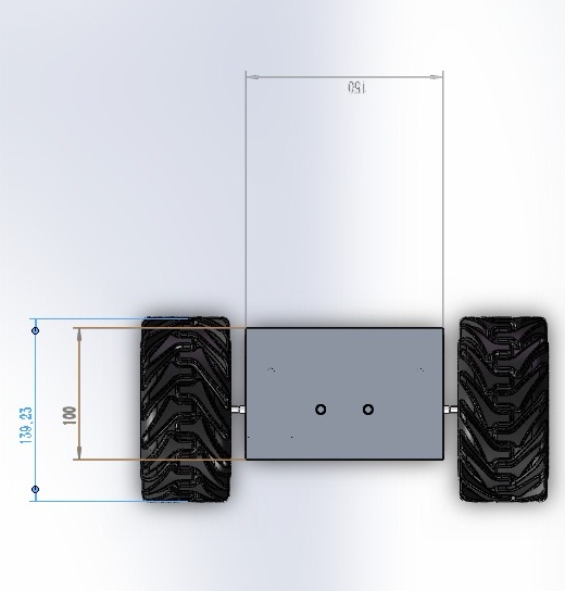
1 Front view
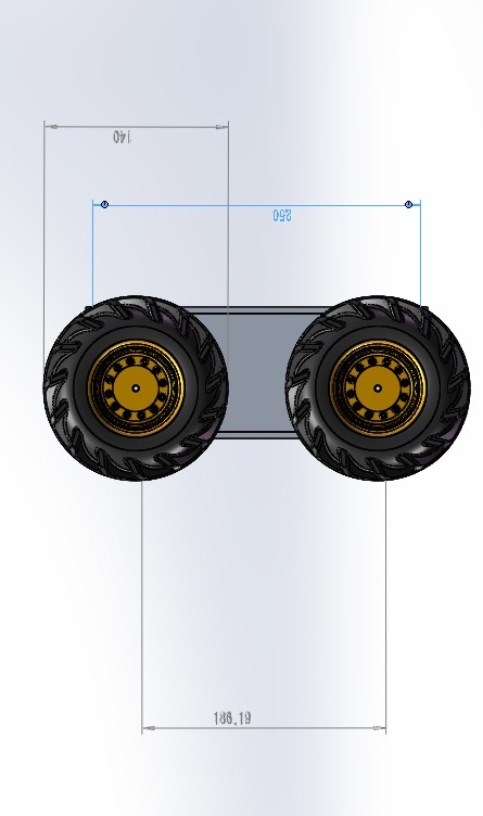
2 Side view
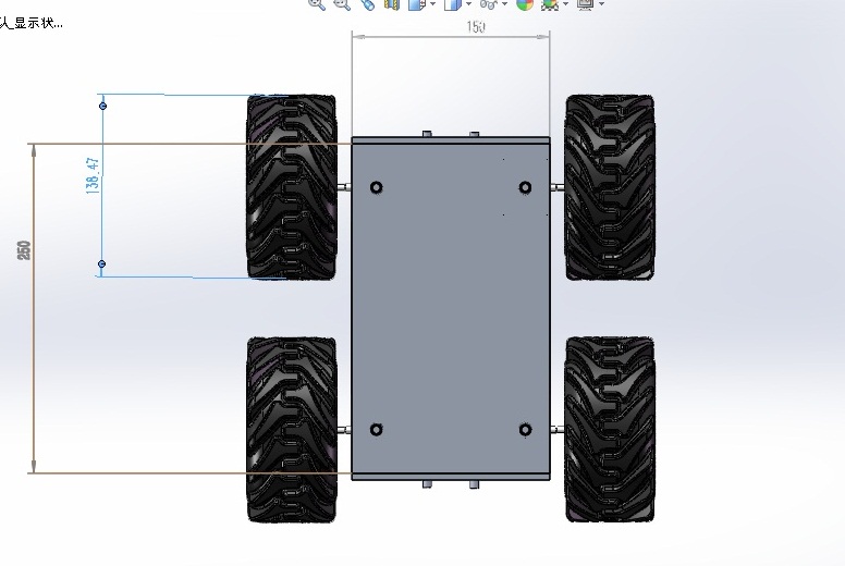
3 Top view
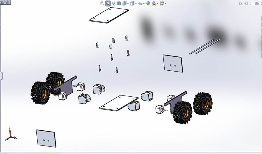
4 Exploded view
(In here you can see that the motor is pushed into the motor housing and
directly driving the wheel since the step motor has low/high torque mode to
serve as gear box itself)
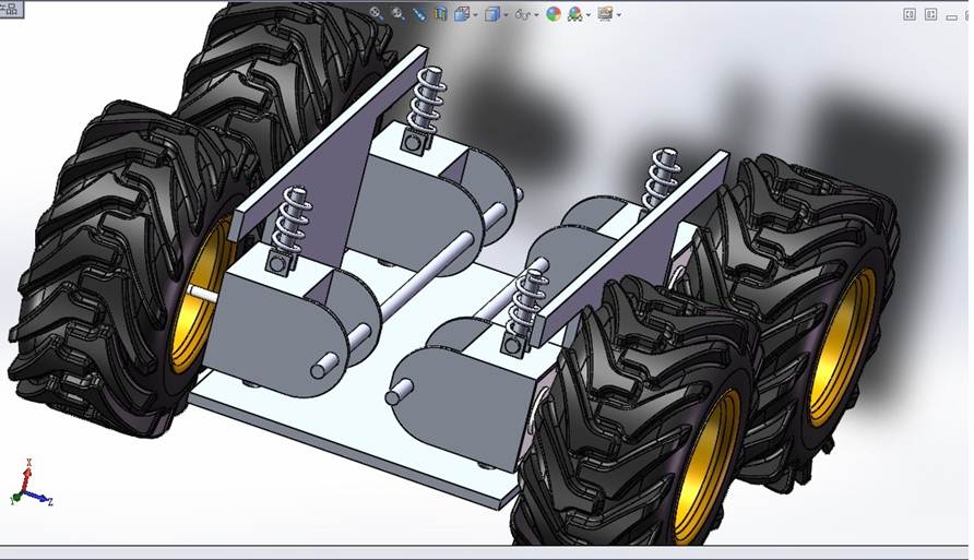
Close look to
the suspension mechanism (it can be seen that the suspension is served as a
simple lever system. The 2 long bolts in the middle which went through the
holes on front and back cover is the fulcrum of the lever, the force applied to
the wheel from the floor to straight up and the force generated by the spring
from up to down is the 2 forces on the lever. The bolt on the motor housing is nut
on the top panel in case that when the car is lifted, the wheel and spring is
staying connected.
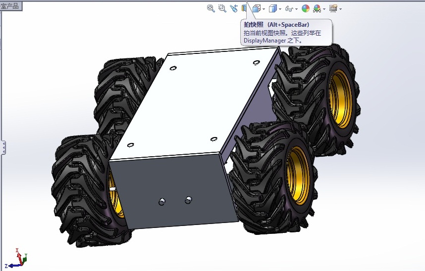
Whole
chassis (a complete chassis weight 1.2 kg from aluminum).
February
16, 2013 (2 hours):
My
teammates reject the chassis design due to following reasons at the meeting:
1.The chassis
suspension system is not necessary since it can be compensated by using foam
and plastic wheel. A suspension system is heavy and consumes a lot of interior
space of the vehicle.
2. The step
motor to drive the chassis is not considered powerful enough since 4 of the
step motor only generate 1.5kg drag force. With a heavy chassis and the high
power consume motor it is not feasible.
Instead of
manufacture of our own chassis, we have ordered Dagu 4wd thumper online.
A change of
chassis design has also affect the power system of the whole project:
The new Dagu
thumper need 7.2V sub-c battery, which means that the project need 3 voltage
level: 3.3v for GPS, 5v for USB device(WIFI and Raspberry Pi,
ultrasonic), 7.2V for the motors.
The team meeting
has decided the new step down regulator and fuel gauge/power management IC
specifically for the current system. NiCd battery has
chosen since it has no memory effect and can provide high power.
WEEK 06 SUMMARY
Accomplishments: Finished the chassis design, chassis parts rationale,User interface discussion
Weekly Work Total: 10 hours
Project Work Total: 39.5 hours
Week 07
February 18, 2013 (2 hour):
Drawn a PCB pin out of the LPC 1768 for the PCB design according to the mbed references.

Symbol

Packaging
library download
February 19, 2013 (3 hours):
GPS prototyping is finished, The GPS module is maestro A-2200A. It supports
GPIO, I2C and Serial output (Uart). As a standard way
of prototyping, an Mbed LPC 1768 is used to function as a “pass
through” between the GPS module and the computer serial port. The GPS
output is standard NMEA 2000 style that output serial character from Uart using baud rate 4800. The Mbed receive the GPS NMEA
data and then send the data to the PC at the same baud rate and then PC output
the data by Tera term terminal.
The active Antenna is Tee biased in the set up for the GPS and antenna:

This is a typical Tee biased antenna set-up. The ac signal and dc power supply
share the positive end of the antenna. In order to prevent conflict of the
power and the signal, the set-up uses a capacitor to eliminate the dc signal of
the power and the inductor to eliminate the ac satellite signal. The value
chosen can be calculated by the following way:
![]()
In here the GPS frequency is 1575.42 MHz, the value of the capacitor and
inductor cannot go below the nominal value on the diagram.
February 20, 2013 ( 4 hours):
LPC 1768 soldering: Trying to solder 100 pin LPC 1768 microcontroller in the break out board at and soldering the power and de-coupling capacitor.
GPS field test: GPS field test is successful at a open area, once the GPS signal is synced, the GPS immediately transfer ASCII code to the microcontroller and the microcontroller will transfer the ASCII sentence to PC via tera term. The GPS sentence is complied with NMEA format.
For example:
$GPGLL,3751.65,S,14507.36,E*77
$GPGLL,4916.45,N,12311.12,W,225444,A
4916.46,N Latitude 49 deg. 16.45 min. North
12311.12,W Longitude 123 deg. 11.12 min. West
225444 Fix taken at 22:54:44 UTC
A: Data valid
February 23, 2013 ( 3 hours):
Mbed dead: The mbed is broken during the test yesterday.Since the Mbed has a tight fit in the breadboard,tools are required to remove mbed from the board, the mbed lost a connection on trace. Zongyang has detected the problem and soldered the trace to recover the Mbed
Ultrasonic: Ultrasonic recieved a trigger and starting to transmit the ultrasonic pulse, when transmitting is complete, the ultrasonic will raise the echo to high and if there is a feed back , the echo will back to low. This mechanism has been tested on the oscilloscope.
WEEK 07 SUMMARY
Accomplishments: Library, GPS prototype, Ultrasonic testing.
Weekly Work Total: 12 hours
Project Work Total: 50.5 hours
Week 08
February 25, 2013 (6 hour):
Meeting : power, prototype The group had a meeting to discuss the final power supply parts for the project, for 3.3V power output we will use LTC3633A and for 5V we will use TPS62052. 5V power supply will bearing more burden since it will drive Raspberry PI. For 3.3V 0.5A is required, and 5V 1.3A is required.
Mbed flash lpc1768: To flash LPC1768, The following sequence has to be followed. Starting the MCU with the Rest pin pulled high, this will make sure that the MCU entering the ISP mode and recieves binary code.Since the Mbed project has a open source library we can incorprate the library to speed up prototyping. But currently ISP flashing is experiencing issues that the microcontroller cannot be connected yet.
February 26, 2013 ( 2 hour):
search for servo:A servo motor is needed for the 360 degree camera to rotate, this camera has to have a rotation degree of 360 degree which is wider than normal servo motor. Sparkfun has middle servo that is 360 degree and provide a relatively low torque which is enough for the camera.
h-bridge: H bridge sample has arrived, It is L298N that has 2 full bridge. Each of the full bridge has 2A current limit.
March 3, 2013 ( 3 hour):
PWM module and H-bridge tested: A PWM signal is generated in Mbed and is used to driven the H-bridge and drive the Chassis motor for one side.only half of the bridge is used. Sot the motor will only travel in one direction. A preliminary design of the PWM control can be:

In here there are 3 mode can be implement in this h bridge
1. Forward by closing s1 and s4
2. backwards by closing s3 and s2
3. electronic braking by closing s1 and s3 (if the two terminal of the motor is shorted, especially for a brush motor, it will create a braking effect.
WEEK 08 SUMMARY
Accomplishments: H-bridge testing, PWM , ISP mode
Weekly Work Total: 11 hours
Project Work Total: 61.5 hours
Week 09
March 4, 2013 ( 1 hour):
prepare for the formal presentation,printing Schematic and PCB
WEEK 09 SUMMARY
Accomplishments: team presentation
Weekly Work Total: 1 hours
Project Work Total: 62.5 hours
Week 10
March 4, 2013 ( 1 hour):
presentation week
March 8, 2013 ( 2 hours):
Vehicle test,stall current:
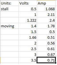
In here the tested subject is just one side of the chassis(2 wheels). Dc generator is directly connected to the Chassis
fuse: A fuse is planned to be used on the H brodge module. Since the Maximun current flow of the H-bridge is 2A. A slow blow fuse is added to allow start-up high current and protect motor when current is exceeding spec when running.
WEEK 09 SUMMARY
Accomplishments: motor test
Weekly Work Total: 3 hours
Project Work Total: 65.5 hours
Week 11
March 4, 2013 ( 0 hour):
Spring Break
WEEK 09 SUMMARY
Accomplishments:
Weekly Work Total: 0 hours
Project Work Total: 65.5 hours
Week 12
March 21, 2013 ( 3 hour):
HW:software design analysis
March 23, 2013 ( 3 hour):
Prototyping Raspberry PI: Raspberry PI wheezy is installed in the Raspberry PI to provide a system. This system has python IDLE that can be used to programming PI. A official issued Python library is downloaded to manipulate the GPIO pin so PI can interact with MCU with a proper protocal through SPI.
WEEK 09 SUMMARY
Accomplishments: GPIO pin manipulation
Weekly Work Total: 6 hours
Project Work Total: 71.5 hours
Week 13
March 26, 2013 ( 4 hour):
Ultrasonic:
Ultrasonic is the device that will provide proximity sensing of the vehicle to the obstacles. These devices is initiated by using microcontroller to assert trigger pulse pin, which is around 10 us wide, then the ultrasonic will start to generate the ultrasonic pulse. When the ultrasonic pulse generation is complete, the echo pin will be asserted by the ultrasonic device. During the edge of the assertion of the echo pin, the MCU should have a interrupt funciton that will start the timer of the MCU to start measuring the time. The assertion of the echo pin will last from 150us to 25ms depends on the proximity of the obstacles. If there is no obstacles, the MCU should stop measuring the time if the echo pin is asserted by more than 38ms and starting to trigger again.
For a more "concise" set up of the ultrasonic, four ultrasonic sensor, which coresponding to the four directions of the vehicle, will share a timer and one trigger pin so the totoal pin consumption will be 5.
After the Echo time is obtained, the proximity can be calculated as time (s)*340m/s/2;
Here is a diagram for the illustration of the ultrasonic timing

March 30, 2013 ( 5 hour):
H-bridge: The previous version of H-bridge is a simple set up. A more conplex set up is required since if the motor is facing stalling, the current will be larger that the specificationof the H-bridge and eventually damage the H bridge.

This is the preliminary set up of the H bridge. you can see that the Hbridge is in the middle of a project boar
d which is screw in the front of the vehicle. The H bridge is protected in 2 ways:
1: the H bridge is using 4 diode to protect the motor from overloading per axis.

In this set up, there are Q1-Q4 4 diodes to reduce the spike of the H-bridge output spike thus protect the H-bridge.
2. The input of the PWM signal to the H-bridge is isolated by using 4 4N33 optocoupler to reducing current flowing through the channel thus the micro controller can be protected
WEEK 09 SUMMARY
Accomplishments: Ultrasonic prototyping, Hbridge modification
Weekly Work Total: 9 hours
Project Work Total: 80.5 hours
Week 14
April 6, 2013 ( 4 hour):
ISP: After further investigation of the ISP machanism, ISP is succesful. The previous trial is failed probably due to the following reasons:
1. Since it is not very optimal to directly connect the computer to the ISP of the MCU that is waiting to be flashed ( the D+ and D- has to be used as serial port), I use a Mbed development board as a relay between the computer USB and the MCU to flash in the binary file. A example code is copied form MBED official site.

2. since the ISP using auto baudrate to sync with the MCU, the MCU has to guess the baudrate that the ISP is using. This guess is achieved by sending character "?" to the MCU and see if the MCU returns this character. If "?" is retured and "sychronized" is dsplayed, then the ISP connection is conplete. But since the MBED relay is used, it is hard to achieve this autobaud since the MBED baudrate is constant, so ISP is hard to be synced.
The standard procedure for the ISP is:
1. using the MBED online complier to compiler and download the binary code.
2. use BIN2HEX to convert the binary file into a hex file.
3. use FLASHMAGIC to flash the HEX file to the microcontroller.
WEEK 09 SUMMARY
Accomplishments: ISP flashing is complete
Weekly Work Total: 4 hours
Project Work Total: 84.5 hours
Week 15
April 8 , 2013 ( 5 hour):
JTAG: Jtag is a better way to program and debugging since it not only providing a way to flashing the MCU, but also debug the code by step through each function.In here a LPCxpresso is purchased to be used as a jtag interface between the MCU and the PC.

this device has two parts.In the left part of the board is the actual development board that has a Jtag interface. In the right part of the board is the base board that has a NXP MCU unit. only the left part of the board is used since we only need jtag part.
The pinout of the jtag connector is:
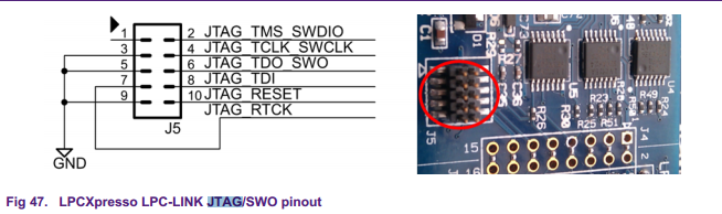
And the pinout on the PCB is :

The standard procedure for the JTAG is:
1. download the LPCxpresso software LPCxpresso IDLE
2. connect the pin on the LPCxpresso jtag and the jtag on the PCB
3. power up the PCB
4. choose "chip select" on the IDE
5. In the chip select window, click the JTAG interface box and load in the binary file
6. click OK and then select the Cortex MCU (the one used on PCB)
7. Wait for the flashing to be complete
WEEK 09 SUMMARY
Accomplishments: JTAG interface complete and installed
Weekly Work Total: 5 hours
Project Work Total: 89.5 hours
Week 16
April 24, 2013 ( 6 hour):
1. flash in code for the team mates to test if their coding is correct
2. soldering the connectors for the ultrasonic and motor
3.360 degree servo:
the 360 degree servo is a servo connect to a self-made 3 to 1 gear ratio to provide 360 rotating capabilities since the original servo can only rotate less than 180 degree.
The servo is working on the width of the PWM module. The accepter input pulse range of the motor, which range from 0ms to 26 ms, represent the 1-170 degree of the moving range of the servo. This range is not constant for each servo so calibration is required.
April 26, 2013 ( 1 hour):
prepare video for the design show case
WEEK 09 SUMMARY
Accomplishments: Servo assmbly, assembly of the code for the project.
Weekly Work Total: 7 hours
Project Work Total: 96.5 hours
Week 17
April 29, 2013 ( 3 hour):
documentation,final presentation
WEEK 09 SUMMARY
Accomplishments:
Weekly Work Total: 3 hours
Project Work Total:99.5 hours