Worked with Mike to create customs parts in Eagle for our pcb layout.


January 10, 2012 (1 hour):
Met as a team after class to discuss preliminary project proposal.
January 12, 2012 (2 hours):
Met as a team after class to finish writing preliminary project proposal.
WEEK 01 SUMMARY
Accomplishments: Submitted preliminary project proposal.
Weekly Work Total: 3 hours
Project Work Total: 3 hours
January 17, 2012 (2 hours):
Met as a team to formulate PSSC for presentation in class on January 25th.
January 19, 2012 (3 hours):
Met as a team to finish the final project proposal.
January 20, 2012 (1 hours):
Researched Parts.
WEEK 02 SUMMARY
Accomplishments: PSSC and project proposal finalized.
Weekly Work Total: 6 hours
Project Work Total: 9 hours
January 22, 2012 (3 hours):
Met as a team to research parts and set up PSSC Presentation
January 23, 2012 (3 hours):
Made the PowerPoint for the presentation. Talked to TA and he suggested that writing a usb driver for XBee would not be feasible because it is really complicated. Thought of using IMUs for motion capture, but wasn't sure if the magnetometer was needed.
January 25, 2012 (1 hours):
PSSC Presentation
January 26, 2012 (3 hours):
Met as a team to finish the PCB layout homework. Finalized on the IMU without the magnetometer.
WEEK 03 SUMMARY
Accomplishments: PSSCs Finalized, PCB layout tutorial finished
Weekly Work Total: 10 hours
Project Work Total: 19 hours
January 29, 2012 (2 hours):
Met as a team to discuss design constraint homework. Divided parts for the homework. Worked on the wireless module design and component selection. Decided to choose XBee Series 1 due to it's low power consumption, plus its simplicity to set up.
January 30, 2012 (2 hours):
Talk to Chuck and TA about Wireless module component selection. Chuck suggested to look at the wireless module by Microchip which was used by the HOARD Robotics team. He also suggested the XStick USB interface for XBee.
January 31, 2012 (2.5 hours):
Worked more on the design constraint homework, put together presentation for TCSP. Improved the set of PSSCs and decided to use a Atom board for the base station.
February 2, 2012 (1 hours):
Worked more on the design constraint homework. Attempted to pick a suitable micro that has enough I2C as well as SPI ports.
WEEK 04 SUMMARY
Accomplishments: Finalized the wireless module to be XBee series 1, and decided on the micro that has enough ports. Worked on the design constraint homework, and put together the TCSP Presentation. Decided to use a mother board instead of a laptop.
Weekly Work Total: 7.5 hours
Project Work Total: 26.5 hours
February 6, 2012 (1 hours):
Met as a team to break down the packaging homework.
February 7, 2012 (2 hours):
Worked on packaging homework and put together the slides for TCSP
February 9, 2012 (1 hours):
Met as a team to break the hardware design and schematics homework. We found out that the development board for the micro we chose is obsolete. And thus we worked on picking a new micro. Harsh found a PIC micro that was suitable to our needs. It also have a lot of documentation and examples for which convenient for our development. Also discussed the possible sketch for the schematics.
February 12, 2012 (3 hours):
Finished the schematic for the hardware design homework. Also worked more on the writing portion of the homework.
WEEK 05 SUMMARY
Accomplishments:
Weekly Work Total: 7 hours
Project Work Total: 33.5 hours
February 14, 2012 (2 hours):
Met as team and talked about the preliminary version of the schematic, discussed possible places for decoupling capacitors and the overall structure of the power supply circuit. Made a updated block diagram.

February 15, 2012 (5 hours):
Laid out preliminary version of the schematic, connecting all important components to the microcontroller. Presented for TCSP in class, learned that a debugging circuit is required for if we want to debug the microcontroller after we soldered it onto the PCB board. Also learned to use a voltage switch regulator instead of linear regulator to reduce power consumption.

WEEK 06 SUMMARY
Accomplishments: Laid out the preliminary schematic, including the power supply circuit, XBee, and imu interfaces. Learned in TCSP that a debugging interface is needed.
Weekly Work Total: 7 hours
Project Work Total: 40.5 hours
Febuary 19, 2012 (1 hours):
Met as team to talk about making a more detailed schematic, and PCB design. Thought about using a LCD to display battery life and wireless signal strength. The downside of using the LCD however, is that if we choose to use a 5V LCD, then we need to somehow produce a 5V input from the 3.3V power supply.
Febuary 20, 2012 (1 hours):
Met as team to split up work for PCB design. Steve is going to implement a charge pump that will charge the 3.3V input to 5V.
Febuary 21, 2012 (3 hours):
Worked with Mike to create customs parts in Eagle for our pcb layout.
Febuary 23, 2012 (1 hours):
Mike had a problem when he tried to debug the PIC32 microcontroller through the debug board. For some reaon the MPLAB could not recognize the board. Played around with the board but still couldn't figure out why, will need to talk to Chuck or TAs about this issue
WEEK 07 SUMMARY
Accomplishments: Decided to use a charge pump to step up 3.3V input to 5V for the LCD, made custom parts library with Mike for the PCB layout.
Weekly Work Total: 6 hours
Project Work Total: 46.5 hours
Febuary 26, 2012 (2 hours):
Started on formal design review. We broke down tasks that have to be done for the review. Found out that there are 3.3V LCDs available from Sparkfun that would fit our deisgn. In the end still decided to use the charge pump since the circuit in the schematic has already been made. Also decided to add a rocker switch to power on/off for implicity of use. Also decided to go with removable battery instead of making a charging circuit since it would be too much trouble, and we packaging design would allow us to easitly detach the battery and charge it.
Febuary 28, 2012 (1 hours):
Talked to TA about adding a bulk capacitor into our schematic. TA suggested that it should be around 50-100uF and there are one available in the lab.
Febuary 29, 2012 (5.5 hours):
Worked on the powerpoint for the deisgn review. Updated block diagram correcting pins and removing the charge pump. We have decided to use a 3.3V LCD found on Sparkfun since then we can remove the charge pump circuit, reducing power consumption and size of the pcb board. The LCD draws less 20mA current which is not a problem since our power circuit can provide up to 3A. Added a reset button onto the schematic, however there are still problems remaining with the pcb board. Thus far the part where the reset button is added is crowded and thus it is hard to route the reset button onto the board. Also there are still some traces that are not connected or have acute angles. One pin from XBee is routed incorrectly to the microcontroller and we need to find a way to route that. Also made a project timeline for the formal review.
March 1, 2012 (2 hours):
Formal Design review. Learned several points in the review. 1) add debuggin pins into the schematic and pcb. 2) Several connections traces are still loose, and there are some acute angles. 3)Someone suggested that the user of the sleeve might be left handed. We need to take that into consideration when making data calculations and displaying image. 5)Talked about possible solutions for having variable length wires.
Full Schematic
 Xbee Portion of Schmatic


WEEK 08 SUMMARY
Accomplishments: Worked on formal design review. Finalized parts for circuit, including taking out the charge pump, using a 3.3V LCD, adding a reset button to the design.
Weekly Work Total: 9.5 hours
Project Work Total: 56 hours
March 5, 2012 (1.5 hours):
Met as a team and broke down modules for each person to complete. Found a paper that details robot arm kinematics which should be really useful when we want to do calculations for displaying the 3D arm. The paper is called "Robot Arm Kinematics, Dynamics, and Control by C.S. George Lee".
March 7, 2012 (2 hours):
Proof of parts briefings. Talked about how to improve the atom board's graphic performance. Chuck said there's not that much we can do except turning off unnecessary applications. Suggested that we should present two vesions on the final demo. One on the atom board and one on a PC. Also learned that we need to add surface aread for heat sink, and use a 16V electrolytic 100uF capacitor. Below is the PCB layout made by Harsh

March 8, 2012 (2 hours):Read more on the robot arm kinematics paper. Found we could use rotation matrices for poistion calculation. Given the rotational and translational motion data from the sensors, we could build a 4X4 rotation matrics that would give us the final position of each joints.
WEEK 09 SUMMARY
Accomplishments: Found a robot arm kinematics paper that would make it convinient for us to calculate arm position, using a rotation matrix build from sensor data. Learned how to improve the pcb board during proof of parts review, including increasing the size of the heat sink and adding bulk capacitors.
Weekly Work Total: 5.5 hours
Project Work Total: 61.5 hours
March 12, 2012 :
Spring Break
WEEK 10 SUMMARY
Accomplishments:
Weekly Work Total: 0 hours
Project Work Total: 61.5 hours
March 19, 2012 (1 hours):
Made the short term goals for each team member for this week. Items that need to be done are: XBee prototyping, IMU prototyping, and power supply circuit. Also made a finalized item purchase list.

March 20, 2012 (4 hours):
Figured out how to configure XBee, including setting up the network ID, communication channel, and baud rates. Found that a logic level translator might be needed, depending on the output voltage for the serial communication pins of the micro. Remaining tasks for programming XBee: connect one XBee to the computer and connect another one to the micro. First need to know what the pin output voltages are, and then write serial communication code to talk to the XBee

March 21, 2012 (0.5 hours):
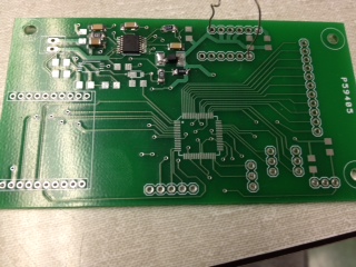
Found out that logic level translator is not needed after talking to TA and Mike and examining the data sheet. The port pins that are going to talk to Xbee are 3.3V which is the same as XBee. Also got the fabricated PCB board today!

March 21, 2012 (3 hours):
Wrote serial communication code that transmits and receive data from XBee.
WEEK 11 SUMMARY
Accomplishments: Xbee Prototyping, figured out how to set up and configure Xbee using a PC. Found out that logic level translator is not needed for XBee. Wrote serial communication code in c to send and receive data from XBee.
Weekly Work Total: 7.5 hours
Project Work Total: 69 hours
March 26, 2012(4 hours) :
Wrote some more code for XBee communication in C. Now I can print character strings to the terminal. Also found out the printf work the same as in C, except that now it prints to the terminal instead of the console. Also soldered the female breakouts to the expansion board. Checked that neighboring pins were not shorted.
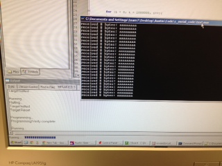
Receiving character strings sent by XBee
March 27, 2012(6 hours) :
Worked on Patent Analysis homework and presentation. Learned how our project might infringe existing patents literally or under the doctrine of equivalents. Found several patents that our projects might be infringing, especially the ones owned by company which made XSense. A product that is really similar to our project.
March 31, 2012(5 hours) :
Tried sending data through XBee again and failed to do so. Spent a lot of time debugging using both HyperTerm and XCTU. I eventually found out that the UART module that the microcontroller is using had been changed for some unknown reason. The microcontroller used to output data from UART3, but now it outputs data from UART2. One thing that needed to be done is to figure out how to configure which UART module that the microcontroller is using.
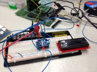
Prototyping XBee
WEEK 12 SUMMARY
Accomplishments: Wrote code in embedded C to send character strings through the XBee module. Soldered breakout pins to the expansion board so that we can use it to debug other prototypes later.
Weekly Work Total: 15 hours
Project Work Total: 76.5 hours
April 3, 2012 (3 hours):
Soldered more pins to the expansion board, as well as to the LCD. Asked Chuck about soldering tips for soldering the microcontroller and other components with small leads. I learned that flux should be applied to the pins that needed to be soldered. Use small tips to melt the solder a little and quickly touch the pins with the tip and swipe away. If there are bridges between pins, apply flux on solder wicks and use that to remove the bridges.
April 6, 2012 (3 hours):
Read more on the PIC32 documentation and found out how to configure the microcontroller to use different modules. The functions that I have been using to open the UART are outdated and thus it was having that abnormal behavior. I tried using the new UART configure function but was unsuccessful to output the string to the terminal. I need to dig into the documentation more. As of now I think it's due to I'm not setting the clock speed right.
April 7, 2012 (7 hours):
Started to look into how to receive serial data on the base station. Since the base station is running Windows XP, I installed MinGW which is a GCC compiler for Windows. I found a software package online that can receive serial data and it is written in C. It's good that the package is written in C since the OpenGL code that is used to render motion data is written in C as well. I also soldered the power circuit onto the PCB board, except a couple components which we haven't received yet. The hardest part was soldering on the LM20143 regulator, however I checked each pin and they seemed to be properly soldered.
Receving function Xbee on the base station
Soldered the power regulating circuit onto the PCB
WEEK 13 SUMMARY
Accomplishments: Learned how to solder components with small leads and soldered the power regulating circuit onto the PCB. Also found a software package that could receive serial data sent from the XBee. Found out built in functions that could configure the PIC32 to use certain UART modules.
Weekly Work Total: 13 hours
Project Work Total: 89.5 hours
April 10, 2012( 3 hours) :
Soldered remaining components onto the power regulating circuit. Tested it and got no output. Debugged it with Steve, and Steve found out that there were no output because we were measuring voltage at the wrong points. Since there were components from other parts that haven't been soldered yet, we needed to measure the output at some other points. We eventually got a 3.6V output which is a lot higher than the expected 3.3V output. We'll need to figure out the reason for that.
April 14, 2012 (8 hours) :
Started to work on measuring the signal strength from the XBee. At first there were no signal coming out of the RSSI pin, which is supposed to output a pwm waveform whose duty cycle determines the signal strength. I read the data sheet more carefully and found out that XBee would only output RSSI signal when receiving data, not transmitting. Thus I wrote a simple test program on the PC that would send random bytes to the XBee connected to the microcontroller. Now the XBee would output the RSSI waveform, however since the two XBees were so close together, the signal strength were always 100% unless I use my hand to cover up one of the XBees.
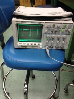
PWM waveform from the RSSI pin from XBee
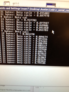
Signal Strength measured from XBee
WEEK 14 SUMMARY
Accomplishments: Soldered more parts onto the power regulating circuit and got a 3.6V output. Wrote test program to capture XBee signal strength.
Weekly Work Total: 11 hours
Project Work Total: 100.5 hours
April 17, 2012 (7 hours):
Found out the reason that the power regulating circuit output was higher than expected. It's because I was using a resistor value that is different than what Steve had used for prototyping. Also found out that there was one missing component that was not soldered. I soldered the missing component as well as the battery monitoring circuit components, and tried measuring the regulated voltage again. There were no output and I had to spend more time to figure out the reason for that. Started working on a XBee library that will have all the functions related to XBee such as sending bytes and measuring signal strength.
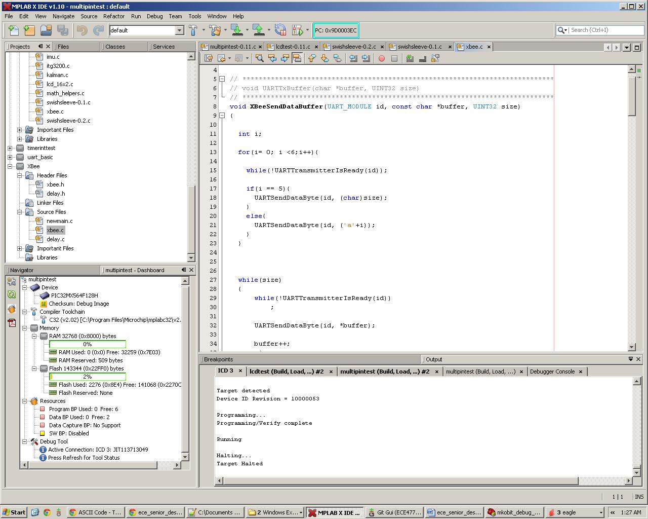
xbee.c in the XBee Library
April 20, 2012(7 hours) :
Finished the assembly and tutorial parts of the user manual. Spend some more time debugging the power circuit and still couldn't find the reason. Steve took all parts in the battery monitoring circuit off but we still couldn't get any output. In the end I resoldered every component in the power regulating circuit and finally had a 2.88V output. It's a little low but once we receive the correct resistors from the mail I can correct that. Also helped Harsh with debugging the I2C communication but we couldn't figure out the reason why there were errors on the bus.
Regulated output from PCB
WEEK 15 SUMMARY
Accomplishments: Debugged power regulating circuit and finally got a acceptable 2.88V output. Finished the assembly and tutorial parts of the user manual.
Weekly Work Total: 14 hours
Project Work Total: 114.5 hours
April 24, 2012 (3 hours):
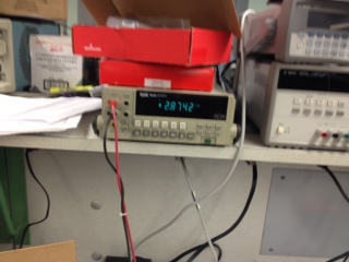
Worked on final report since I will be the one that is responsible for it. Worked on figuring out the packaging of our project and how to best present it in the report. Soldered resistors with correct values onto the power circuit and got a 3.0V which is really good. The voltage is expected to rise after more load is attached to the battery since more current will be drawn.
\
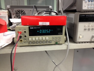
3.0V output from the power regulating circuit
April 25, 2012(8 hours) :
Continue on making a XBee library that would have all the functions required to perform serial transmission through XBee. Having a library will make it easier for Mike to write the main loop. I wrote a XBeeTransmitDataByte function that would take a pointer to the start of a buffer and transmit the whole buffer through XBee. I also wrote a XBeeConfigure function that would configure the UART module as well as other necessary components to use the XBee.
April 26, 2012(12 hours) :
Worked on synchronizing the sending and the receiving end of the serial software. Due to timing issues sometimes the receiving end process would lose the first few bytes of a transmission, and start reading at the middle of the package. I solved this by appending a start sequence every time I send a package to the receiving end. The receiving end would ignore all data until it receives a complete start sequence. This successfully solved the synchronization issue. I also worked on reading the signal strength from XBee. Since the signal strength is presented as a PWM waveform I needed to determine the duty cycle of that waveform. I used three input capture functions and a timer to record the time stamp of each rising and falling edge. From those time stamps I calculated the duty cycle of the pwm waveform. The precision of the duty cycle were improved from the previous attempt, however the values still jump within a certain range. I am going to look for a better way to improve the precision, perhaps taking averages of multiple trials. I also incorporated the function that measures the signal strength into the XBEE library.
April 27, 2012(12 hours) :
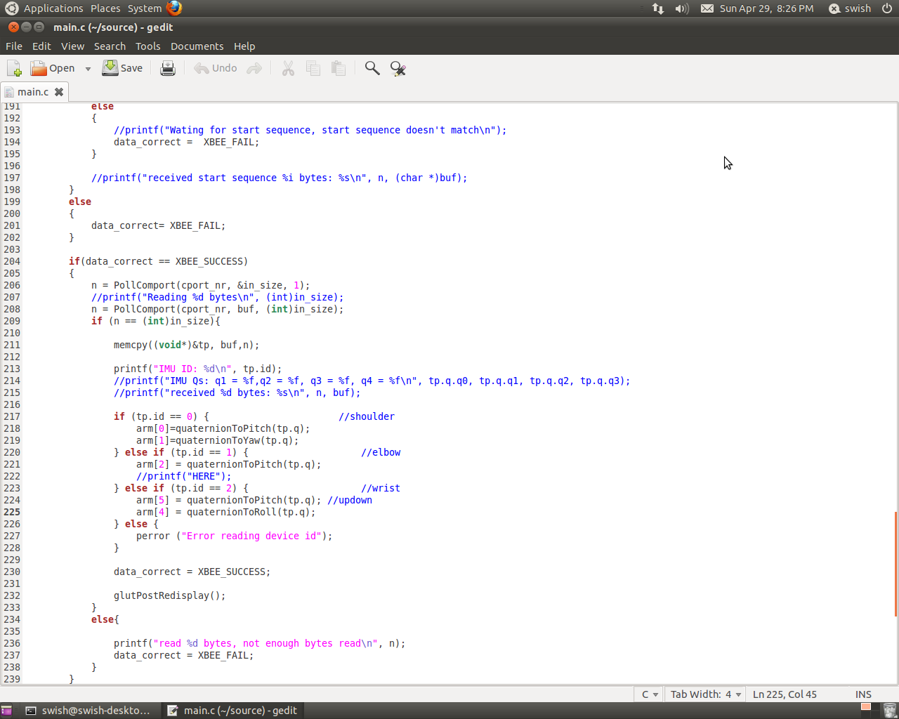
I ported the test program that I wrote into Steve's OpenGL code on the atom board. The program loops and waits for incoming data. It will see if the first five bytes received is the correct start sequence and start receiving data after-wards. I then helped Mike to write the XBee related part of the Mainloop. We did a test run, as we send live Quaternion readings from the IMU to the base station through XBee. The test was successful as the received data was completely correct. The only issue is that there is a few seconds time delay before the base station would receive the data. We suspected that it is because we were doing a lot of print statements and the OS is constantly blocking for IO. I also started to look into possible ways to have the receiving process to be interrupt based to save time from busy waiting.
April 28, 2012(10 hours) :
Helped Harsh with debugging the microcontroller programming circuit but was unsuccessful. He later found out that the pin layouts in the manual were incorrect. Soldered some headers onto the PCB board, and worked on final report. It took a lot of time because everyone had different formatting in their homework. Also took pictures of the schematic as well as project packaging.
April 29, 2012(10 hours):
Spent more time working on the final report. Wrote the final version code for XBee signal strength measuring. Discussed packaging and PCB board issues with the team. There is one trace that is short, and we also need to jump wire the ground plane to one of the pins. Also found out that the Din and Dout pins for the XBee were incorrect in the PCB board. We will ask Chuck about this on Monday.
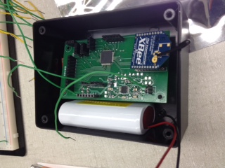
Waist Unit Packaging
WEEK 16 SUMMARY
Accomplishments: Wrote a XBee library that includes all the functions for sending and receiving data through the XBee, as well as capturing the transmission signal strength. Figured out a way to synchronize the sending and receiving nodes. Incorporated program that will receive serial data into the OpenGL code. Finished final report.
Weekly Work Total: 50 hours
Project Work Total: 164.5hours