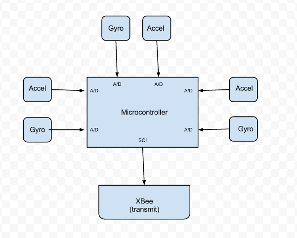
Met as a team to finish the final project proposal. Created the Block diagram for the transmitter component, and I took responsibility for the PCB Narrative and Prelim Layout, and Reliability and Safety Analysis.
January 10, 2012 (1 hour):
We met as a team to discuss the preliminary project proposal. I also setup a shared google calendar and google docs folder to centralize all the homeworks, presentation and additional documents for reference purposes.
January 12, 2012 (2 hours):
Finished Homework 0, Preliminary Project Proposal, as a team.
WEEK 01 SUMMARY
Accomplishments: Submitted preliminary project proposal.
Weekly Work Total: 3 hours
Project Work Total: 3 hours
January 17, 2012 (2 hours):
Met as a team to formulate PSSC for presentation in class on September 7.
January 19, 2012 (3 hours):
Met as a team to finish the final project proposal. Created the Block diagram for the transmitter component, and I took responsibility for the PCB Narrative and Prelim Layout, and Reliability and Safety Analysis.

January 20, 2012 (3 hours):
Stephen and I spoke with the TA about the PSSCs and drew a rough sketch of the design. Our prototype consists of two components: base and transmitter where the base station receives data from sensors and after few mathematical computations displays on monitor. Meanwhile the transmitter extracts data from sensors and wirelessly transmits to the base station.
WEEK 02 SUMMARY
Accomplishments: PSSC and project proposal finalized. Created block diagram for the transmitter component.
Weekly Work Total: 8 hours
Project Work Total: 11 hours
January 22, 2012 (3 hours):
Met as a team to research parts and set up PSSC Presentation
January 23, 2012 (3 hours):
Researched about the relevance of the magnetometer and its applicability with our product. Narrowed the list of possible sensors that meets the criteria of being able to capturing precise 3-D movements.
Gyro:
Triple-Axis Digital-Output Gyroscope - ITG-3200
MPU-6050
Accelerometer:
Triple Axis Accelerometer - ADXL345
Triple Axis Accelerometer - ADXL335
LilyPad Accelerometer ADXL335
Magnetometer:
MicroMag 3-Axis Magnetometer
Magnetometer Digital Triple Axis - HMC5883L
Triple Axis Magnetometer Breakout - MAG3110
January 24, 2012 (3 hours):
Met with the TA to discuss about the sensors and came to the realization that we will have to purchase the sensors on breakout board. The individual sensors are QFN and impossible to sauter due to their size. Also researched on how I2C protocol is implemented and compared SCI vs UART for the Xbee module.
Sites for research:
www.i2cprotocol.com/
en.wikipedia.org/wiki/I²C
http://en.wikipedia.org/wiki/Universal_asynchronous_receiver/transmitter
January 25, 2012 (1 hours):
PSSC Presentation
January 26, 2012 (3 hours):
Met as a team to finish the PCB layout homework. Proposed two IMUS that are cheap and meet the required specs to the team and decided to use the IMU breakout, which offers 6 degrees of motion, that includes both an accelerometer and gyro. It is the IMU Digital Combo Board - 6 Degrees of Freedom ITG3200/ADXL345 that will use I2C to communicate with the Microcontroller.
WEEK 03 SUMMARY
Accomplishments: PSSCs Finalized, PCB layout tutorial finished and finalized the sensors to use.
Weekly Work Total: 13 hours
Project Work Total: 24 hours
January 29, 2012 (2 hours):
Organized the team meeting concerning the completion of the Design Constraint Homework. I was responsible for selecting a feasible microcontroller and analysing cost constraints by comparing with a similar product in market. I worked with the team to determine what interfaces are required by the microcontroller and then researched for suitable micros by two major manafacturers: Atmel and Microchip.
January 30, 2012 (2 hours):
I decided to select a microcontroller from Atmel, ATxmega128A1, because the micro matched the specs we were looking for and IDE (AVR Studio 5) for programming was user friendly than compared to Mplab (PIC IDE). Also requested Chuck for Atmel the STK 600 development board and also asked him what other components are necessary to use the development board to sync with the microcontroller.
January 31, 2012 (4 hours):
Found a similar product to our prototype in the market for cost constraint analysis. Also improved the set of PSSCs and decided to use a Atom board for the base station. I also installed AVR Studio 5 and USB driver to interface with the development board.
Febuary 2, 2012 (1 hours):
Found out the socket board to sync the micro with the development board is obsolete and the micro is new to market which poses a threat for unpredictable hardware issues. Discussed with Chuck the possible alternatives.
WEEK 04 SUMMARY
Accomplishments: Found various options for micro-controllers that match required specifications. Finished my share of the Design Constraint homework and determined the advantage to use the atom board for 3-D simulation. Determined possible issues that might be present with very new components.
Weekly Work Total: 9 hours
Project Work Total: 33 hours
Febuary 6, 2012 (2 hours):
Met as a team to break down the Packaging homework. I was in charge of determining the PCB footprint layout. After rigorous research, I ruled out that it is not feasible to use Atmel due to various component being obsolete or out of stock.
Febuary 7, 2012 (4 hours):
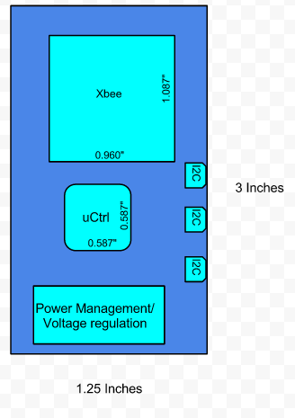
Found a couple of options for PIC microcontroller and narrowed the option further down by limiting the microcontroller options to the PIC32 family. Read user manuals for Mplab C compiler and PIC32 family datasheets. I drew the preliminary PCB footprint layout to meet our main product requirement, portability and compact.
Febuary 9, 2012 (2 hours):
Met as a team to break the hardware design and schematics homework. After confirming that all components relevant to programming and burning a microcontroller are available, I finalized to use the PIC32MX795F512H microcontroller that has 4 I2C, various SPI, UART and TIM modules with an internal oscillating clock. Furthermore, I emailed Chuck requesting for the Explorer 16 development board and the M320003 socket. The Microchip website an abundant source of documentation such as reference data sheets, sample codes, etc. I provided Augustus with the Eagle file that allows creating a schematic with the specific microcontroller.
Febuary 12, 2012 (1.5 hours):
I also wrote part of the hardware narrative for HW 5 concerning the usage of SDA and SCL pins for I2C communication with the IMU and the usage of the TIM module.
WEEK 05 SUMMARY
Accomplishments: Finalized the microcontroller, PIC32MX795F512H, and read quite a bit of documentation for programming the Microcontroller. Also contributed with HW 4 by completing the PCB footprint layout section and partially completing the hardware narrative section for HW 5.
Weekly Work Total: 9.5 hours
Project Work Total: 42.5 hours
Febuary 14, 2012 (2 hours):
Completed the Hardware Design Narrative part for HW 5 and then also helped look for possible eagle parts libraries for the micro and other major component. Most components had a downloable eagles parts library except for the PIC 32.
Febuary 16, 2012 (2 hours):
Reinstalled MPlab and also the specific Mplab C compiler for the Pic32 micro. Also attempted to setup communication with the development board.
Febuary 17, 2012 (2 hours):
Looked for resources that would help in programming the pic-32 and found the book called "Programming 32-bit Microcontrollers in C" by Lucio Di Jasio. Read the introductory as far as setting up a project. Also used it as reference to setup communication with the develoment board.
WEEK 06 SUMMARY
Accomplishments: Wrote the hardware narrative component for HW5 and started work on the software end of the micrcontroller. I started researching on connecting proper communication between PC and develoment board.
Weekly Work Total: 6 hours
Project Work Total: 48.5 hours
Febuary 20, 2012 (1 hours):
Met as a team to discuss the PCB narrative homework that I was in charge of. The homework was divided into part where Steve worked on the power component, Augustus assigned the overall section and Mike handled the intro and conclusion. I worked on micro considerations for PCb portion of the homework.
Febuary 21, 2012 (4 hours):
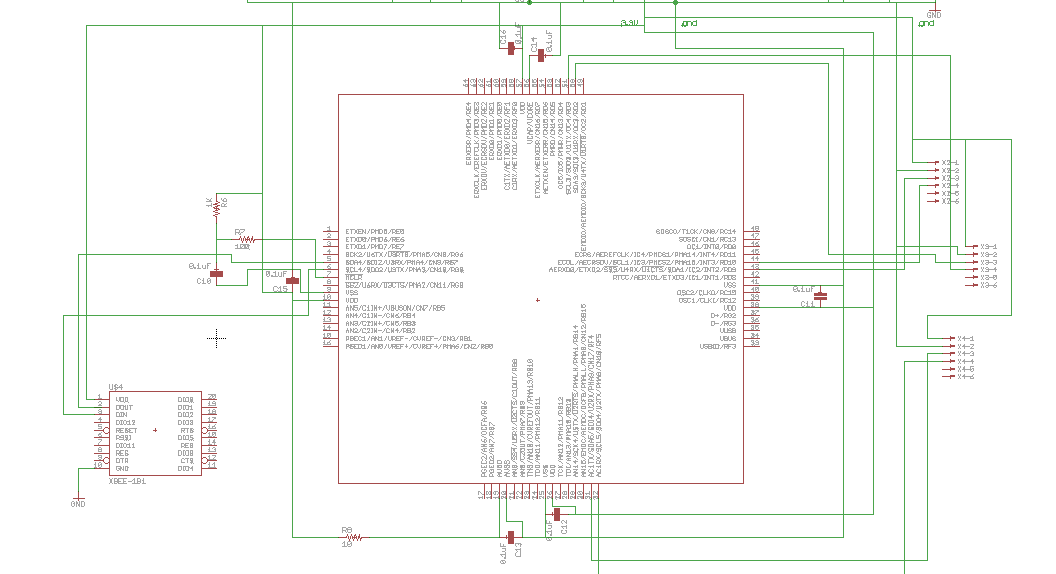
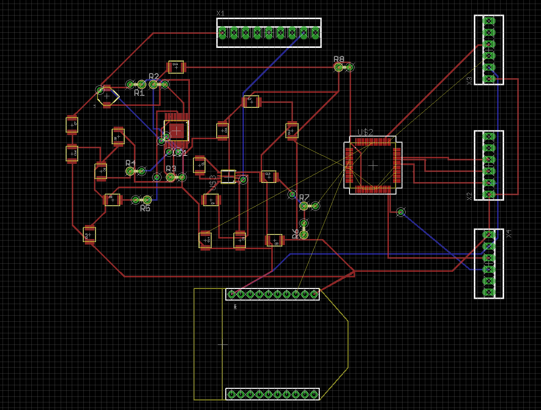
I started work on creating the apporpriate schematic and attempted to route the PCB. Implemented the ICSP debugging component and determined necessary pins for XBee. I also determined the appropriate decoupling of the micro and attempted to autoroute in hopes of the computer magically routing on its own.The images below display the schematic of the micro with decoupling layout and the auto routing attempt.
Febuary 22, 2012 (2 hours):
I put together the powerpoint for the presentation and also did last minute fixes to the schematic.
Febuary 24, 2012 (2 hours):
Redrew the schematic so that it is less cluttered and easier to verify. Also, I worked specifically on redrawing the switch voltage regulator and charge pump.
WEEK 07 SUMMARY
Accomplishments: Drew the appropriate schematic for PCB that includes ICSP debugging, IMU and LCD interfaces. Also prepared and presented PCB narrative. I attempted to route the PCB to see how to do it using EAGLE.
Weekly Work Total: 9 hours
Project Work Total: 57.5 hours
Febuary 27, 2012 (7 hours):
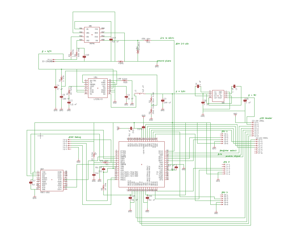
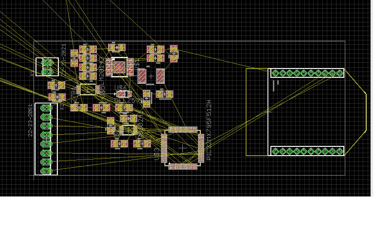
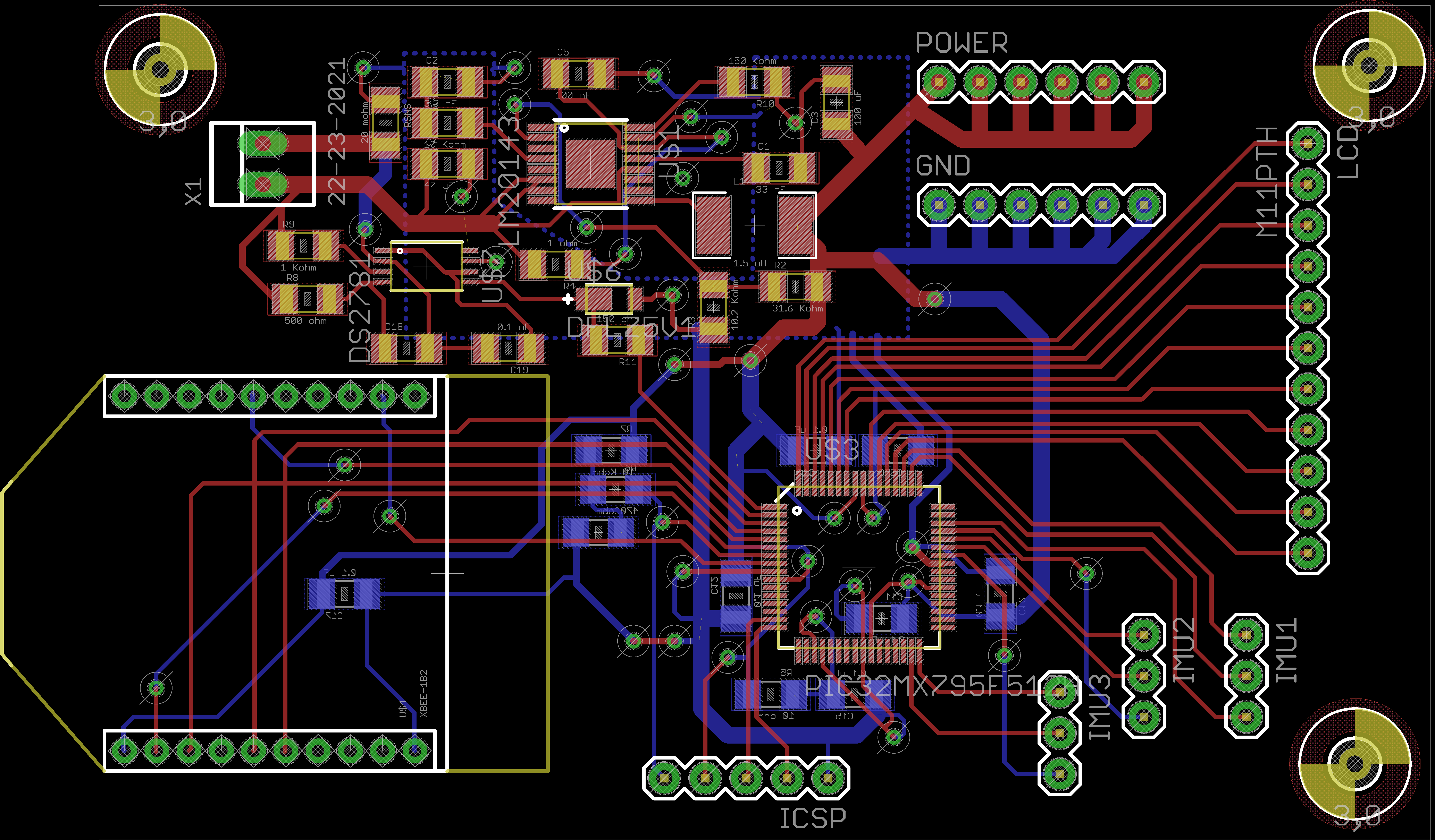
Restructured the schematic to include all headers and routed by hand. Trying to organize all components within 1.5" x 4.5" dimensions. I included the battery monitoring component to circuit. The images below demonstrate the redraw schematic and the PCB routing in progress.
Febuary 28, 2012 (5 hours):
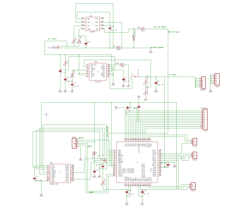
Reevaluated necessary headers and removed the charge pump cicuitry. We as a team opted to use an LCD that would use 3.3 volts instead of 5 volts to avoid the extra circuitry for voltage conversion. Redrew schematic again and tried to group each side of the micro carefully in terms of choosing pins wisely.
Febuary 29, 2012 (9 hours):
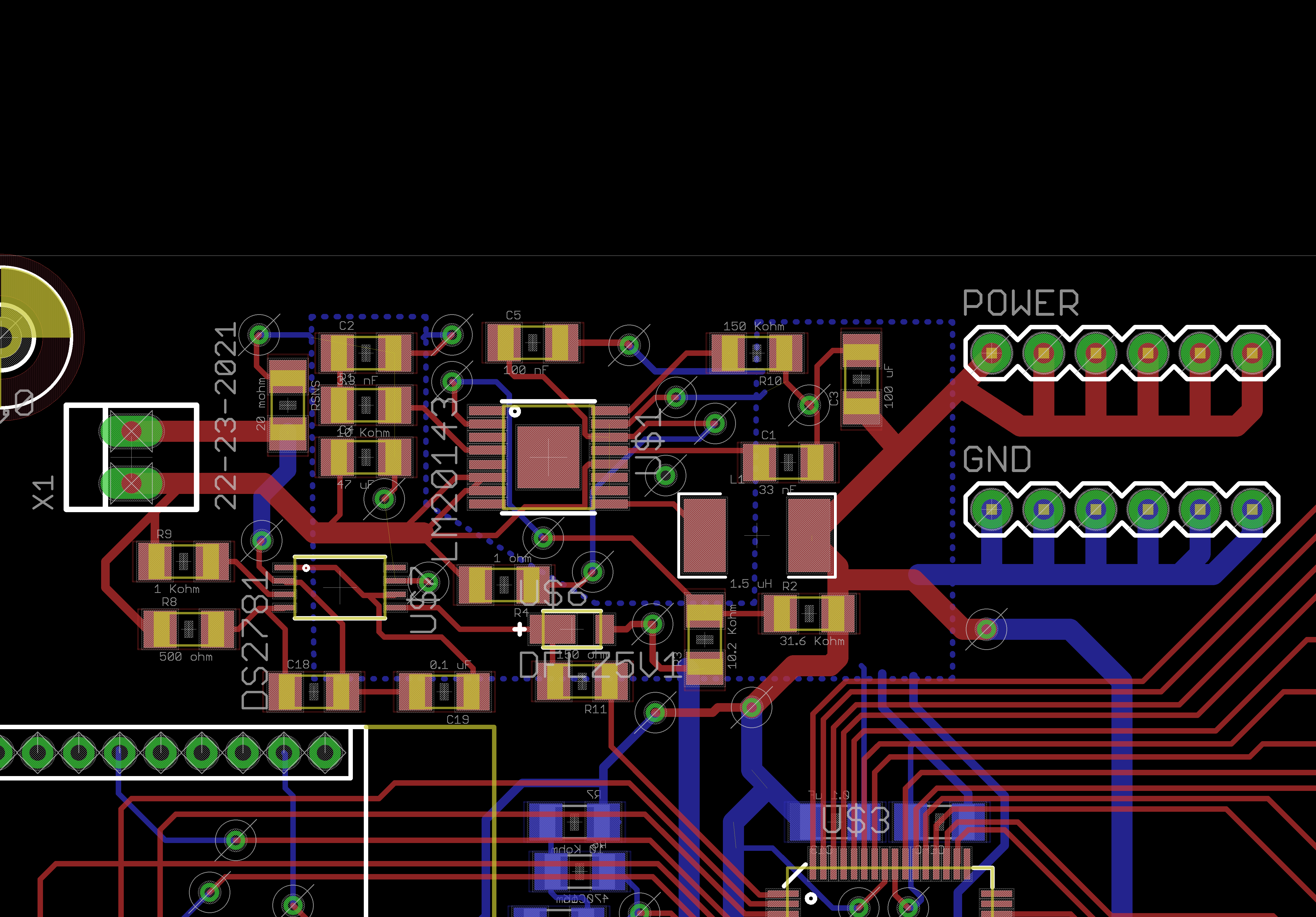
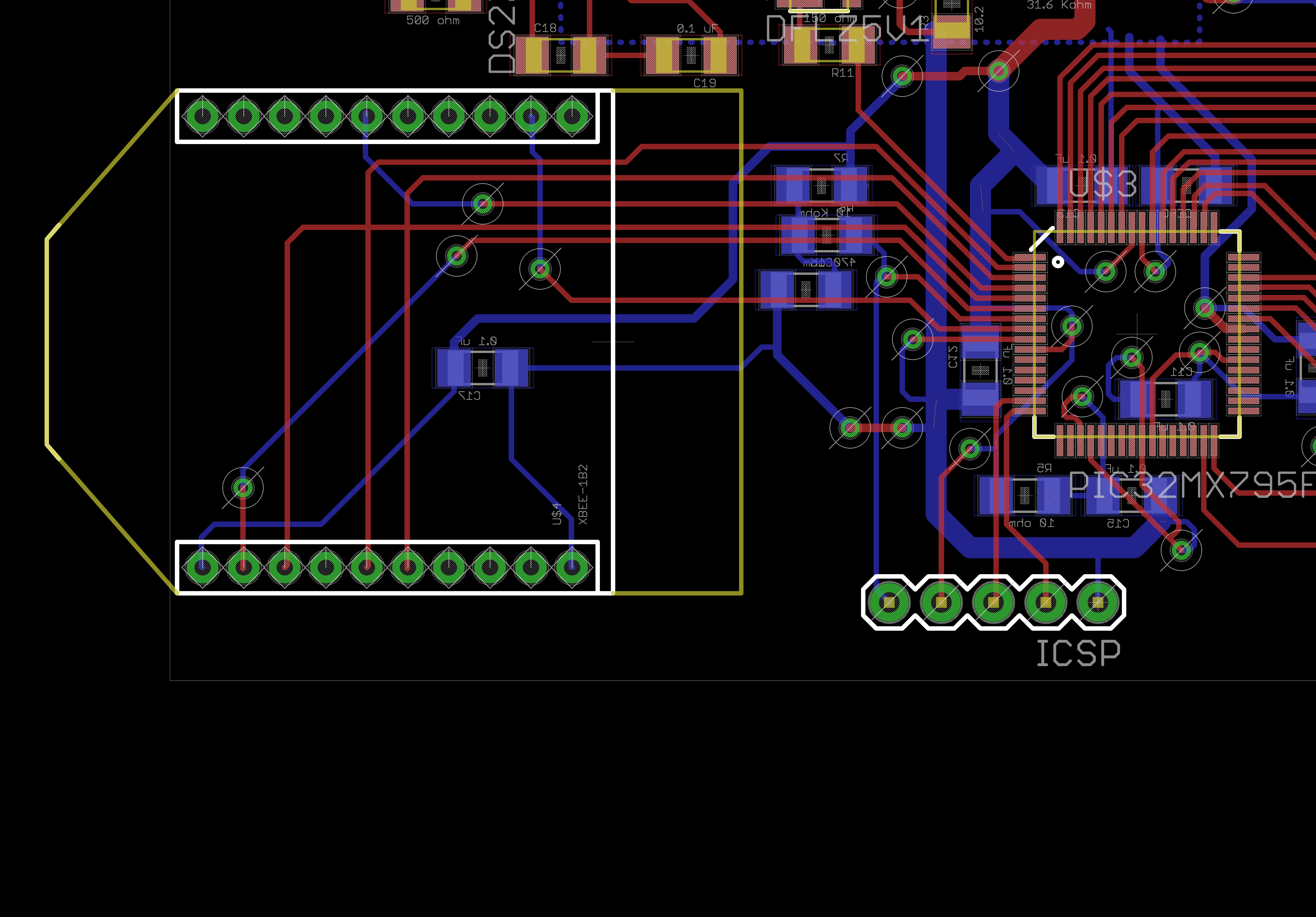
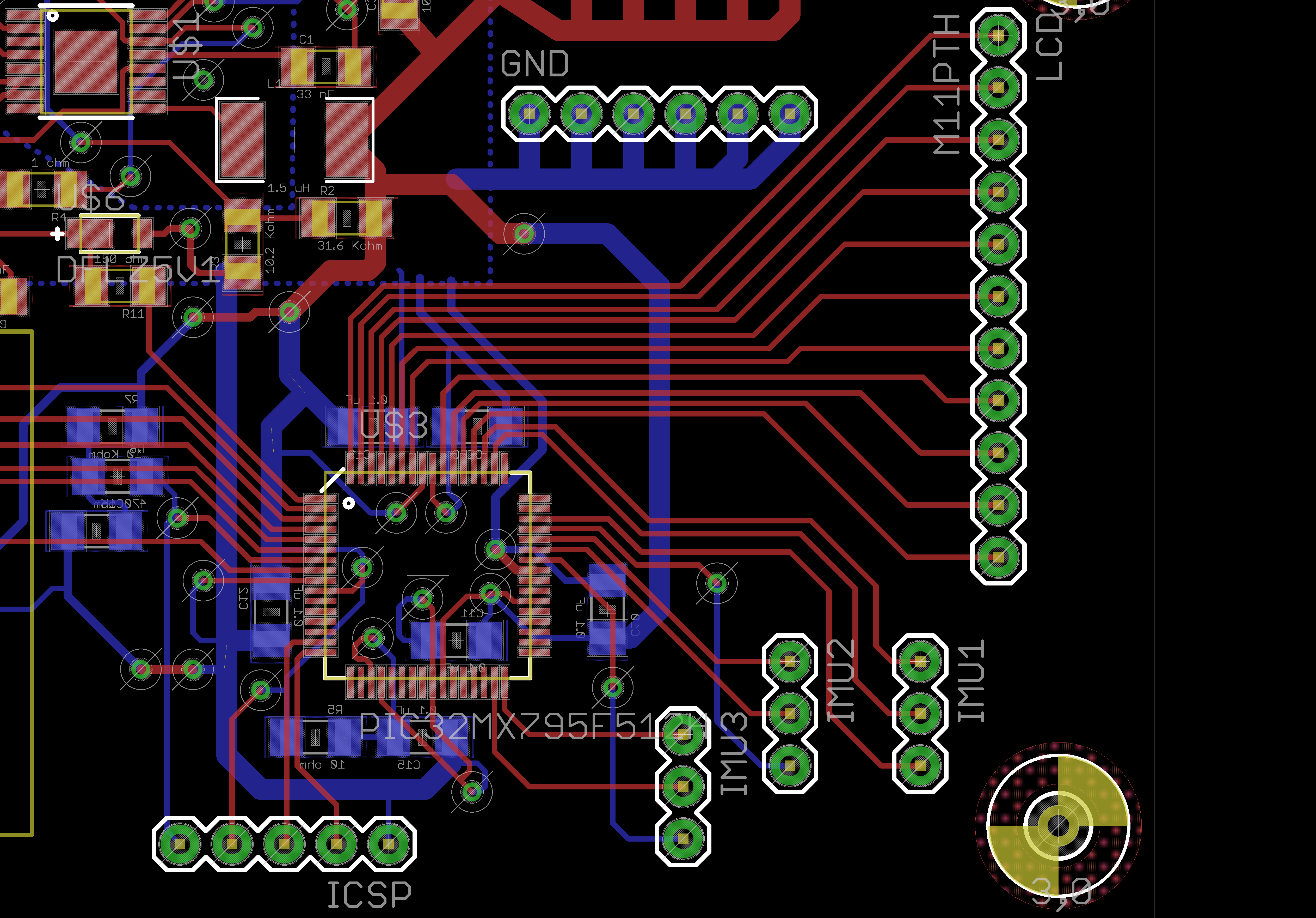
Rerouted the PCB and tried to avoid criss-crossing traces as much as possible. Also changed the headers to the ones from sparkfun lbr headers MXX and made a dedicated power and ground headers. The images below show various areas of the pcb that have been routed:
POWER SECTION
XBEE SECTION
OVERALL BOARD
HEADERS
March 1, 2012 (1 hours):
Included the PCB layout components necessary for Design Review Presentation. I also discussed the strategies for presentation and printed all documents with help of Steve necessary for the presentation.
WEEK 08 SUMMARY
Accomplishments:Finalize the schematic that would satisfy the requirements we have for our unit on the waist. Also, organized and routed a double layared PCB as compactly as possible within dimensions of approximately 1.5" x 4.5". I also contributed by putting together part of the Design Review presentation.
Weekly Work Total: 22 hours
Project Work Total: 79.5 hours
March 9, 2012 (5 hours):
Worked with TA, George, on Friday to solve any issues that came up when running DRC in EAGLE for our PCB and also get the Parts Acquisition HW checked off. Resolve more than 160 errors and once I resolved the issues I ran the necessary tests and submitted the files that Chuck needed to have the PCB fabricated.
WEEK 09 SUMMARY
Accomplishments:I debugged any issues that the PCB and submitted our design for fabrication. Also got the Parts Acquisition HW checked off.
Weekly Work Total: 5 hours
Project Work Total: 84.5 hours
March 14, 2012 (6 hours):
Using the textbook from the library as reference, I started learning and coding how to initialize certain pins of the microcontroller. I learned that the multifunctional capabilities of the pins on pic-32 microcontroller requires accurate declarations. For example, PORT B pins need to be declared wether they are they output or input pins; furthermore, it is necessary to signify if the pins have an analog or digital signals that are being analyzed. I also wrote an example program to initialize the Timer module and worked on how to use the various tools in MPLAB before actually programming the microcontroller on the development board. The simulation tools are very helpful in keeping track of outputs and debugging possible issues with the logic.
WEEK 10 SUMMARY
Accomplishments: Learned and began to initialize the microcontroller pins and some of the modules such as TIM and SPI.
Weekly Work Total: 6 hours
Project Work Total: 90.5 hours
March 19, 2012 (6 hours):
I started to work on setting up I2C and what all configuration bits are required to appropriately provide a 80 Mhz signal. I researched and found that the internal clock can function at 8 MhZ and what are the values of the divider and multipliers that are needed along with other bits that disable watchdog so that it doesn't interfere during communication with Xbee or IMU.
March 21, 2012 (4 hours):
I researched on the steps to establish a multibyteread, single byte read and single byte write. For single byte reads that will be needed for receiving data from the IMU, I noticed that first we configure the I2C module and declare start transfer then we need to send the slave address to IMU which returns an acknowledge signal if that slave exists. After acknowledgement, we notify the slave that we will be doing a read sequence and specify what register we will be reading for.
WEEK 11 SUMMARY
Accomplishments: Figured out configurationn bits relevant to the oscillator component and other functionalities such as DEBUG and watchdog. I also learned about particular features of I2C and proper communication protocol.
Weekly Work Total: 10 hours
Project Work Total: 100.5 hours
March 26, 2012(10 hours) : Wrote up a test code to establish communication with the IMU and running into a lot of issues in terms of being able to start transfer and receiving acknowledgement back from the IMU. Read documentation on appropriate I2C communication setup for ITG3200 (gyro) and ADXL345 (accelerometer).
March 27, 2012(10.5 hours) :
Realized the ITG3200 has a slave address of 0x68 and ADXL345 has a slave address of 0xA6. Trying to do a single byte read from register 0, the WHO_AM_I register, to verify if the address is accurate. The I2C bus is showing sporadic behavior where bus collisions are occuring at various areas such as when transmitting the slave address and waiting for acknowledgement. Also at time, the micro hangs when establishing a start transfer of the I2C.
March 30, 2012(10 hours) :
I am not able to setup communication with the IMUs so consulted with Justin from Team 1 as to how they has setup their I2C module. Double checked if I was executing the commands in the same sequence as Justin and mine was the same. I am not sure as to why it is not working so double checked the connections and everything seems to be working. I had Justin test the IMU to verify if there was any issue with the IMU but he was able to make it work appropriately. I am wondering whether the issue is related to the Micro or software in general.
WEEK 12 SUMMARY
Accomplishments: Wrote test code to establish communication with IMU via I2C module.
Weekly Work Total: 30.5 hours
Project Work Total: 131 hours
April 2, 2012 (4 hours):
Started writing the Reliability and Safety Analysis report and put together a presentation for the presentation on Wednesday.
April 3, 2012 (4 hours):
I determined our three most critical components: the microcontroller, the fuel gauge circuit and the voltage regulator. Calculated the failure rates based on the military handbook, MIL-HDBK-217F and then made the FMECA tables for the three critical componenets.
April 5, 2012 (3 hours):
Attempted to establish communication with the IMU but failed to do so. I cross checked the slave addresses and they were correct. I spoke with Jusitin and the TAs to determine possible issues but no one knew the issue.
April 6, 2012 (1 hours):
I proofread the document for any missing components and submitted
WEEK 13 SUMMARY
Accomplishments: Completed the Reliability and Safety Analysis homework and worked on trying to debug software to get I2C working.
Weekly Work Total: 12 hours
Project Work Total: 143 hours
April 10, 2012( 10 hours) :
Checked multiple forums and then finally submitted a ticket to MicroChip asking about the issue. I also decided to test my code with Justin's microcontroller, the PIC32MX360F512L, that he was using. It seemed to be working so I narrowed the issue beig with the microcontroller. I am successfully able to do single byte reads and single byte writes to the gyro and accelerometer but not sure why the multibyteread is not working.
April 11, 2012( 4 hours) :
I found the silicon errata sheets for the PIC32MX795F512L and saw there was a critical issue with the I2C modules where the SDA line has problems. I discussed with the group what our options are and realized either we follow the fix around that MicroChip suggested or use another microcontroller of the same family. Fortunately found another microcontroller with same specs, dimensions and layout. The PIC32MX564F128H is a stable microcontroller with no issues metioned in the silicon errata sheets with the I2C module so we decided to go with the another microcontroller.
April 12, 2012( 10 hours) :
Realized that the in order to establish multibyte read we need to also specify to the IMU the register we would like to start reading from. The IMU then autoincrements the register after every read and once the master, microcontroller, has read the number of bytes that it wants to it sends a not acknowledge signal to terminate data transmission from IMU. Testing with the gyro starting showing results in the x,y and z axis in terms of adc value which needs to be converted to degrees per second. However, the acclerometer is sending correct data.
April 13, 2012( 3 hours) :
The datasheets indicated that the accelerometers default setting is at sleep mode so have to specifically have to write to the PWR_CTRL register in order to keep it in the wake mode. Both the accelerometer and the gyro are working so the data just needs to be inputted to the kalman filter. The x,y and z coordinates are 2 byte values so after every one byte read have to concatanate to get the appropriate value.
WEEK 14 SUMMARY
Accomplishments: Found an issue with microcontroller and came up with an alternative solution. Also managed to get multibyteread, singlebyteread and singlebytewrite work for the PIC32MX364F512L.
Weekly Work Total: 27 hours
Project Work Total: 170 hours
April 16, 2012( 4 hours) :
Waiting for the real microcontroller and other parts to arrive from digikey to arrive so that we can start to debug everything on the PCB. Meanwhile, interfaced my test code to display printf statements over the com port. This allows to read data that the micro has and if the kalman filter is actually working.
April 11, 2012( 4 hours) :
I am trying to create a main program to combine all the components such as have the reading from the IMU, running the data points through the Kalman Filter and out to the atom board via Xbee.
WEEK 15 SUMMARY
Accomplishments: Started to structure the overall software for the final product. I also added additional debugging features to help with debugging the kalman filter and see reading from the IMU.
Weekly Work Total: 8 hours
Project Work Total: 178 hours
April 24, 2012 (10 hours):
Got help from chuck to mount the micro onto the PCb and then working on setting up programming and debugging capabilities. Faced issues with the appropriate communication with the ICD3 so realized the pin layout is different from what I had anticipated. After rerouting the wires, I was able to establigh communication with the ICD3 and successfully be able to program.
April 25, 2012(20 hours) :
I threaded 4 wires together of the appropriate length from the wrist to the waist along the body. Bought a 20 gauge wire so that not to compromise the clock signal and helped with soldering components onto the PCB. Also worked with group with integrating and testing individual components that are crucial for the meeting our psscs.
April 26, 2012(10 hours) :
Working on the Senior design report, final Report Individual contribution and couple of sections relevant to the final report also. Figured out some of the issues with the PCb wiring and had to fly wire some areas.
WEEK 16 SUMMARY
Accomplishments: Work on senior design report ans also parts of the final report. I helped the group with soldering and packaging our product.
Weekly Work Total: 50 hours
Project Work Total: 228 hours