Marcelo Leone's Notebook
Week 01
August 23, 2011 (1 hour):
The team met after class to discuss the project and organize ideas in a brainstorming manner. It is
necessary to make sure all valid constraints are considered so as to not begin working and come across too
many obstacles.
August 24, 2011 (1 hour):
The team met after lab to prepare the preliminary project proposal and hammer-out the specific details
of the design. It was decided that the HUD would display/include GPS, a compass, temperature, speed,
rear-view camera, night vision, G-force, and range.
August 25, 2011 (1 hour):
The team met after class to finish writing preliminary project proposal. Team roles were determined
along with the initial description of what the project should encompass.
WEEK 01 SUMMARY
Accomplishments: Clarified the scope of the project and submitted preliminary project proposal.
Much brainstorming was done about what can be accomplished in this project and an attempt to analyze
possible physical and technical constraints was made.
Weekly Work Total: 3 hours
Project Work Total: 3 hours
Week 02
August 29, 2011 (1 hour):
Searched for possible helmets online and ended up purchasing one from ebay. Emphasis on a large size
and longer front bill was kept in mind. Also, conducted research on possilbe options for a range-finder
and found that a Sharp IR Range Finder would be appropriate (will discuss with team). It is definitely
afforable, not very bulky, and easy to interface with - however the distance might not be long enough for
the application of the design.
August 30, 2011 (2 hours):
The team met to prepare the final project proposal. The projector also arrived in the mail so there
was quite a bit of experimenting done with it since it's physically here now. Things that were noticed
were that it can get quite warm after long time use, it is fairly bright except when displayed on a clear
surface, and the focus of the image is limited to the surface it is displayed on. These things have caused
the team to begin considering another option for the projection piece of the project - Liteye LE-750A.
However for such a device funding will be needed. The five PSSC's were created and with hopefully enough
'elbow room' right now so that the constraints aren't broken later on if the design specs change slightly
due to the issues with the projector idea.
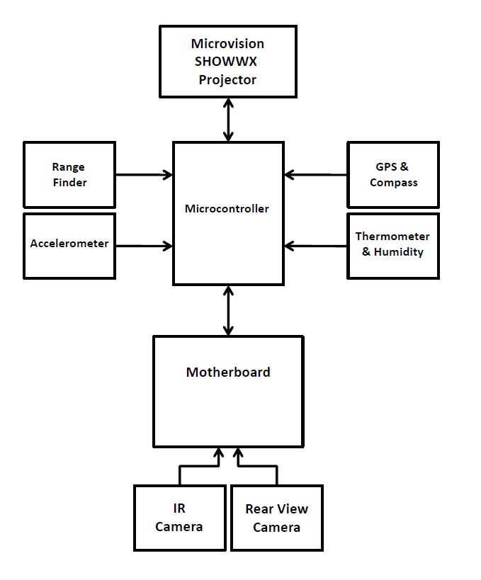
Using the lab computer, the following high level block diagram of the project was created. Part names
are still up in the air as research for the best parts is currently under way (see Google Code Wiki for
links).
August 31, 2011 (.5 hour):
Conducted more research on range finders. Posted appropriate links on the google code wiki to show to
the team tomorrow during the meeting to finalize the final project proposal.
September 1, 2011 (2 hours):
Met as a team to finish the final project proposal. The block diagram was altered a little bit after
much deliberation was made over what should actually be included in the peripherals. After reviewing the
feedback on the original proposal it was apparent that the team needed to make a concrete decision on what
the design will accomplish.
When the team analyzed the findings of the research done on range finders, it was decided that
including a range finder would not be a feasible peripheral due to the fact that one with considerable
distance and accuracy would cost too much. Also, most commercial range finders for long distance are for
recreation and do not have any digital output. Aditya is going to attempt contacting someone to discuss the
possibility of funding.
WEEK 02 SUMMARY
Accomplishments: Began acquiring parts for the design including the helmet and projector.
Submitted the final project proposal and conducted a lot of research on rangefinders, accelerometers,
motherboards, and projectors.
Weekly Work Total: 5.5 hours
Project Work Total: 8.5 hours
Week 03
September 6, 2011 (2 hours):
The team met after class to begin working on Homework 2 and to touch base on the progress of the
design. Team members split up and two worked on setting up the libraries for the PCB parts provided by
Chuck. There were a few issues that came up but with the help of the TA, the layouts and footprints of all
the parts were successfully added to the library. The other two worked on creating the presentation for the
TCSP which will be presented in class so the design can be critiqued.
September 8, 2011 (3 hours):
Worked on one of the laptops provided by the course to complete the PADS tutorial (Homework 2). Also,
the team got together to discuss plans for ordering a motherboard (possibly Atom will be sufficient, and
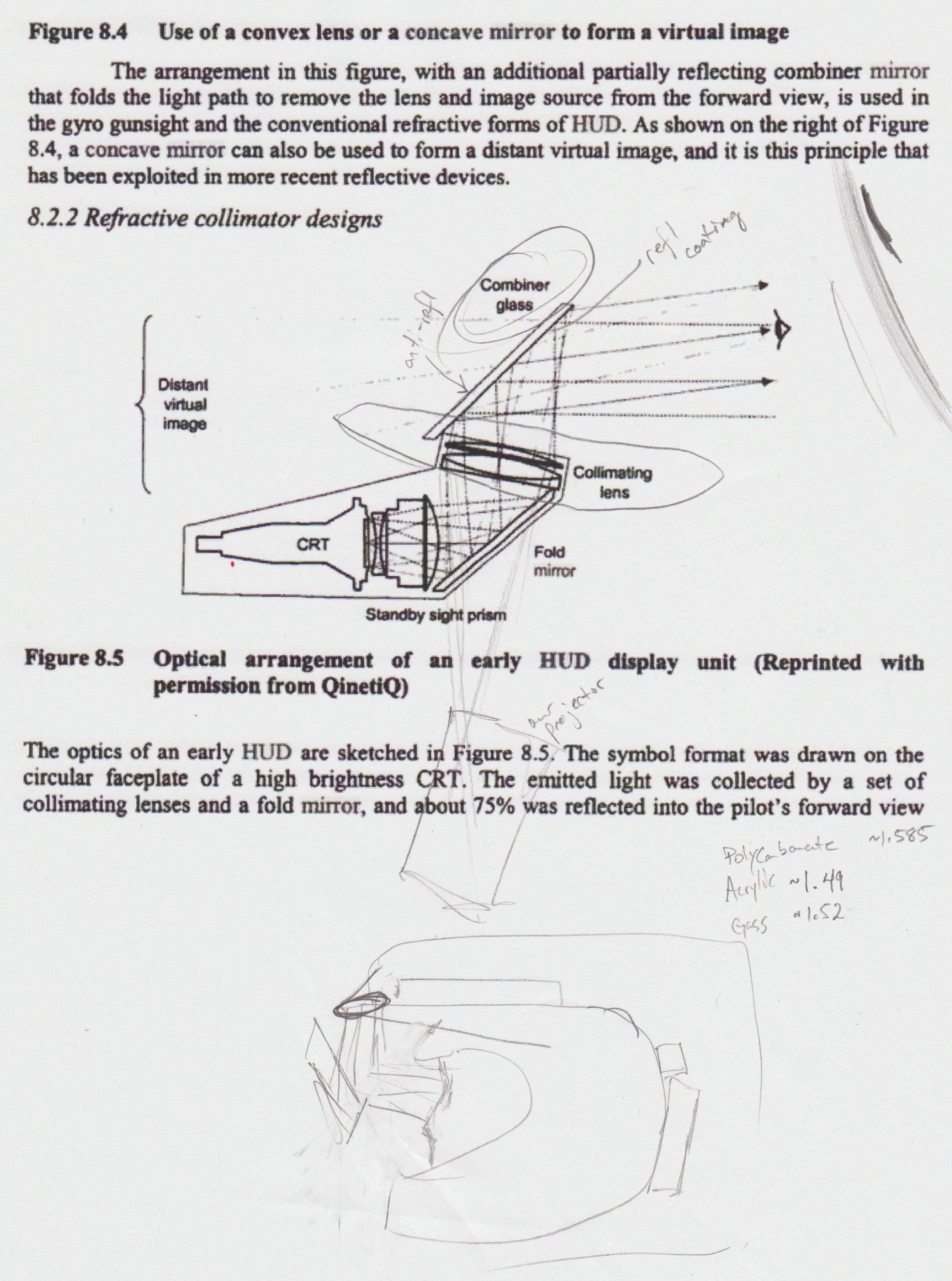
free!), the discovery that a compass will be too complex to implement in our design, and that the projector
will need to be complemented with a collimating lens, a mirror, and some combiner glass in order to get an
acceptable display for the user to be able to see clearly. This realization was because Aditya brought in
an old helmet which had a visor and the projector was not very effective on it. Thoughts were that the
curvature might have a role in distorting the projected image. This aspect of the project will be more
difficult that originally thought. An image that better describes the system needed follows:
September 9, 2011 (1 hour):
Went to TA office hours to get homework 2 checked off and turned in. Also, the helmet bought on eBay
arrived in the mail. Spent some time assembling it and adjusting the padding on the inside so that there
will be room to place some components in the front beak.
WEEK 03 SUMMARY
Accomplishments: Ordered the MMA7361
accelerometer and some sample
PIC32's. Also narrowed our motherboard choices down to the one described here which Chuck will get for us. Developed an
initial plan for the HUD display but more research/experimentation is needed.
Weekly Work Total: 6 hours
Project Work Total: 14.5 hours
Week 04
September 15, 2011 (3 hours):
Met in the lab with the team to help finalize homework 3. Read and edited the report that Aditya had
written, and reflected on the advice given from the TCSP the day before. Also spent time thinking of ideas
on how to mount the components onto the helmet. The team has to consider waterproofing and ventilating those attachments so the
device is robust. One main question is whether or not our battery or batteries will be able to be mounted on the helmet. If only
one battery is used to power our device it will have to be fairly big (and heavy) in order to have a relatively long 'life' between
recharging periods - this will be too cumbersome on the helmet and a backpack might also have to be incorporated with a connection
going to the helmet.
The fiberglass that Aditya ordered came in, along with the reflective and darkening tint. So an
experimental piece was cut and tinted for a make shift visor (as the new helmet does not have its own). It is rectangular in shape and has the reflective tint on
the inside and darkened tint on the outside. When the projector is shined on it (from the inside) the image
displayed seems to be moderately better than before. I think this reinforces the need for the combiner
glass method.
WEEK 04 SUMMARY
Accomplishments: Completed the Design Constraint Analysis, tested the effectiveness of window tint
for the display visor, organized a solution for supplying power to the system of components, and tested the
I/O and ATD functionality of the microcontroller.
Weekly Work Total: 3 hours
Project Work Total: 17.5 hours
Week 05
September 20, 2011 (4 hours):
Created the powerpoint for the packaging TCSP and began typing up the report for homework 4. Basically
had to organize ideas that the team has already discussed and describe all the constrained that have been
analyzed. Some packaging mock-ups were made using a photo editing program and and some pictures of the
helmet from the eBay website.
September 21, 2011 (2 hours):
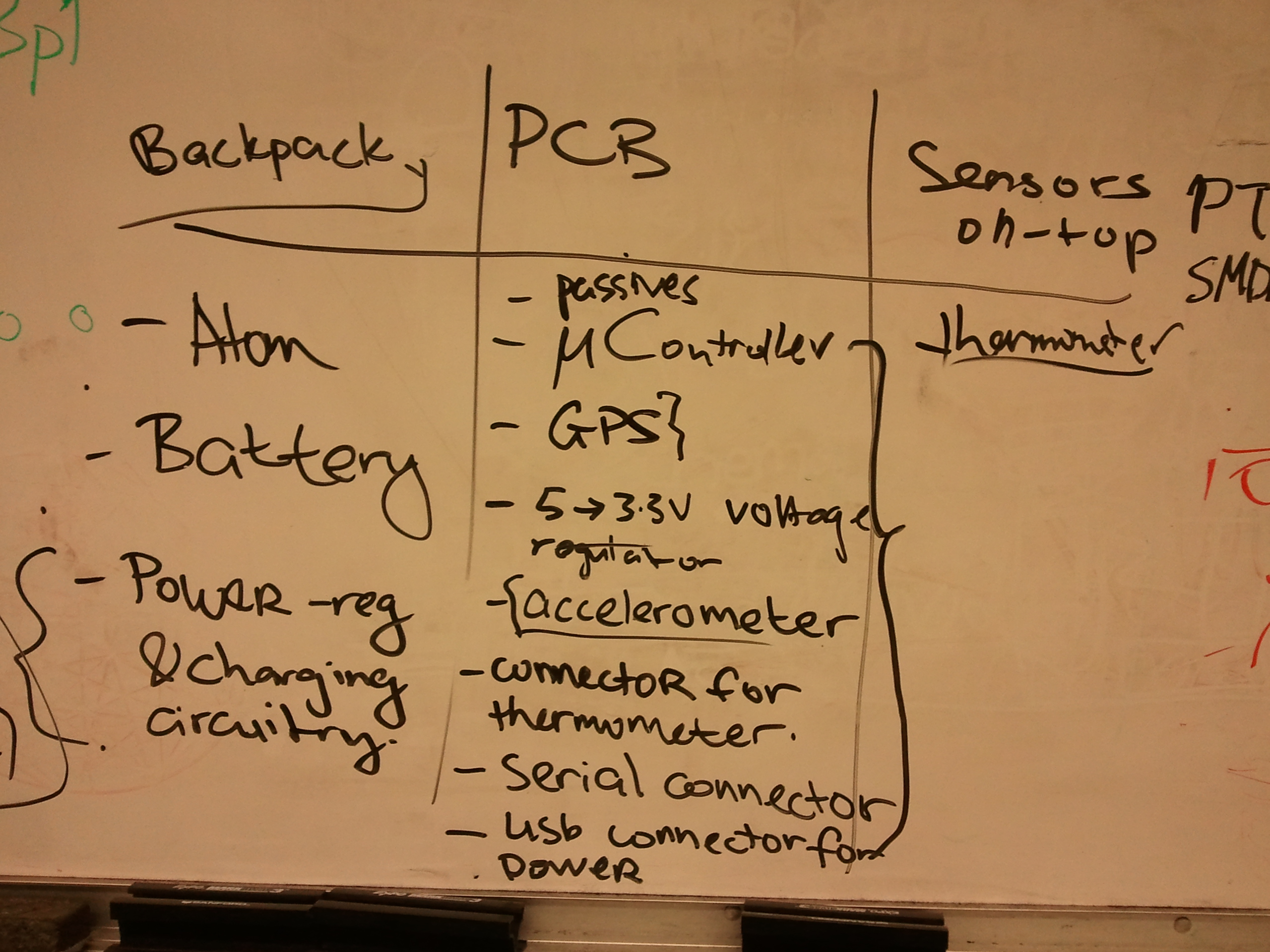
Typed the rest of the report in the lab. Asked for feedback from the rest of the team and got some
re-generated auto CAD pictures for the appendices. Spoke with Aditya and Nikhil about the footprints
necessary for the report. Also, did some brainstorming to get a total encompassing view of the packaging.
Our notes on the white board are below.
September 22, 2011 (3 hours):
Sat with Aditya and Nikhil in the lab and collaborated on the rest of the auto CAD drawings and PCB
footprints while finalizing the Packaging Specifications and Design. The 3D images were of the helmet
(2 different views) and of the peripheral box that will end up going into a backpack.

It ends up that the battery will be too heavy for our overall device. Relative to
the rest of the packaging it makes the most sense to have it sitting in a backpack unit that will be
connected to the rest of the helmet by come cables. And because the backpack unit is a sure thing now, it
was decided that the Atom motherboard and voltage regulator PCB could go in with this unit as well. With
all of these components now contained in one unit, the need of two fans is greatly apparent since there
won't be any airflow like there would have been in the previous design.
WEEK 05 SUMMARY
Accomplishments: The GPS was tested and debugged and the PIC is soldered to a breakout with
necessary capacitors -working now. Component footprints have been drafted for the schematic. CAD models of
the helmet and off helmet backpack unit have been visualized. The packaging specification design was
written and submitted.
Weekly Work Total: 9 hours
Project Work Total: 26.5 hours
Week 06
September 27, 2011 (3 hours) :
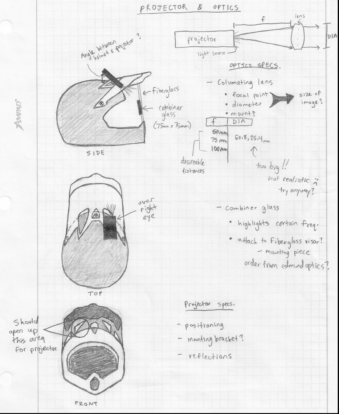
Spent time in lab with Aditya analyzing the optical challenges we have yet to nail details on. The
options that were discussed were related to altering the projected image coming from the projector with a
collimating lense and then enhancing the projection with combiner glass (plate beamsplitter). After
brainstorming and searching commercial products online, the solution decided for now is that the glass
will definitely be used so as to 'highlight' the figures of the projected data (solely green, because
that color is most easily seen by the human eye) and the lense is going to be too big for the helmet unit,
based on the focal point/diameter needed in order to focus the image correctly without making it too small.
This means that the image may not have the 'floating effect' as was originally hoped.
As for the actual placement of these parts (projector, lense(?), and glass), some sketches were drawn
to help plan out further action with such packaging. Took a while in altering a part of the visor to open
up some space for the projector to sit in a place where it can still shine forward onto the fiberglass
(and future combiner glass). The sketches and notes are below:
September 28 2011 (2 hours) :
Met in lab to review over the TCSP that happened previously in the day. Also talked about adding a
charging IC and fuel gauge to the design in order to accomodate the user with notification on battery
levels - something we didn't think of but is actually very important! This addition is leaning us towards
the idea that it might be best to contain almost all of our components (except thermometer, projector +
optics, and maybe the accelerometer) in the new backpack unit... more to discuss with this. Then sat with
Blaine for a bit and helped debug ADC parameters and connecting the accelerometer with the micro.
September 30, 2011 (3 hours) :
Conducted some more research on collimating lenses and combiner glass (plate beamsplitter). Found the
lowest priced beamsplitters were sold by Edmund Optics. After ensuring that we knew all of the correct
specifications for the glass, a 75mm by 75mm piece was purchased with 75% reflection and 25% transmission
of 550 nm light (bright green!). As soon as this comes in, much work will be done to solidify the viewing
visor which will consist of fiberglass and this plate - the challenge will be mounting it to the helmet
while keeping it safe for the user and durable for actual use without blocking the view! Spent a little
time again sitting with Blaine looking at the output of the accelerometer which was coming out not as was
expected. The initializations of the parameters seemed right but the resulting g-force calculations were
consistently a little off.
WEEK 06 SUMMARY
Accomplishments: Made progress on a final battery pack, new battery management circuiting, the
functionality and purchasing of optical elements, and recent packaging alterations. Accelerometer was set
up and much of the initial debugging was done. A new schematic and block diagram were drafted to comply
with the most updated version of the project.
Weekly Work Total: 8 hours
Project Work Total: 34.5 hours
Week 07
October 4, 2011 (5 hours) :
Took some time to test the LM335AZ temperature sensors. Based from the data sheet, was able to build the following
circuit:

The potentiometer will be used to calibrate the output of the thermometer,
which is in volts. According to the data sheet 2.982 volts is 25 degrees celcius (about room temperature).
Once a reliable thermometer is brought into the lab then the sensor can be accurately calibrated and then
mounted onto the helmet. Afterwards spent some time for Blane to show me the working acceleromter and his
newly designed '0 G-force simulator' - when the sensor reads 0 G's, a.k.a. during freefall, the mirco will
record the 'Hanlgtime' which will then be included in the display (really cool!!!). Last bit was spent
sitting with Nikhil making the updated schematic using Eagle software. Were able to use footprints from the
Sparkfun library but also had to make some custom ones for the peripheral headers and connectors.
October 5, 2011 (1.5 hours) :
The combiner glass came in the mail today so some preliminary work was done in lab to see how its going
to work in combination with the projector and a lens. A basic convex lens was found laying around on a
workbench so that was used for now until the collumating lens is purchased. So far, the glass seems very
reflective and it specifically highlights green light. The main concept right now will be how to position
the projector and glass so that the display won't get reflected into the user's eye while its infront of
their face. Luckily the glass is actually very thin, so a possible mounting mechanism could be created to
attach to the visor of the helmet!
October 6, 2011 (3.5 hours) :
Started work on the Design Review presentation. Created a good template to fill out what needs to be
included in the content and then bulleted out 4 or 5 slides such as the Project Specific Success Criteria,
the updated block diagram, the packaging design, and the component criteria/reasoning. Also sat with
Aditya while he was finishing the updated schematic for the PCB layout. Most of the parts for that are
ordered now - just a few mOhm resistors, an inductor, and a couple capacitors still need to be purchased.
October 7, 2011 (1 hour) :
Went with Nikhil to mee with his contact Paul, a graduate student with considerable experience in optics.
Many ideas were discussed on how to achieve "infinite focus" for the projection displayed on the HUD. Paul
looked at the projector and the combiner glass and told how he would expect them to work best with a convex
mirror. An analogy was made to car side mirrors - "objects in mirror are closer than they appear". From that
phrase it was inferred that a convex mirror (or concave lens) would be able to expand the light from the
projector to have it focus further than the surface of the glass when shined onto it. The notes from the
meeting are below:

WEEK 07 SUMMARY
Accomplishments: The accelerometer is completely proto-typed and giving accurate readings, and the
thermometer has been tested. Many updates/changes to the schematic and therefore the PCB as well have been
done in an attempt to finalize every aspect of them in time for the upcoming design review. Much headway was
made in the optics part of the design. The combiner glass came in and that led to preliminary "playing" with
how the projector image is illuminated onto it, with and without a lens in between them. After having sparked
questions on how exactly this infinite focus was going to work, we met with a contact to discuss our possible
courses of action - more team deliberation to come.
Weekly Work Total: 11 hours
Project Work Total: 45.5 hours
Week 08
October 11, 2011 (4 hours) :
Met with the team to touch base on what needs to be done for the review later in the week. Aditya finished
the schematic while Nikhil manually routed the PCB. All of the parts now fit on the PCB because a few headers
were eliminated and the DB25 connector was no longer needed - a direct connection between the PCB and
motherboard/battery is now implemented because of the decision to have all of the main electronic components
in the backpack module and no longer on the helmet.
Continued to work on the design presentation.
Covered all of the component selection rationale and the packaging design summary. Also moved the slides that
Blaine did at home into the main draft copy. Afterwards, slightly took apart the Atom motherboard that got
delivered to Chuck to get a glimpse of its packaging situation. The case doubles as a heat sink which will be
perfect with the combination of the fans combined into the back pack unit. Also, it was discovered that the
SD card was not included inside at all, and the RAM that was on the board was less than what we asked for. To
get around this issue we ordered the necessary parts online.
October 12, 2011 (4 hours) :
Worked in the lab to finish the design presentation and give a "progress report" to the professors. The
schematic and back pack unit CAD drawing were added - these were split up to make each part easier to see on
the slides. All that needs to be added to the presentation is the PCB snapshots which can be done tomorrow
before we rehearse in a EE classroom. In addition, time was spent updating the notebook based on the feedback
from the TA.
October 13, 2011 (4 hours) :
In preparation for the design review the next morning, touched up and re-worked parts of the presentation document.
Wanted to make sure that there wasn't too much text on each slide but that they still outlined what was going to be said.
To make the schematic and PCB easier to read/view on the projector screen we zoomed in on the pictures in the slides and made animations to shift the different parts of the images. After deciding who would present what parts of the powerpoint, went with
Aditya to EE 317 to make sure all of the slides looked good on the screen and that there were no other technical difficulties.
Some work on the documentation for the Intel competition application was also started. Nikhil and Aditya are going to finish some parts at home.
October 14, 2011 (2 hours) :
Went into the lab just for a little bit to review on things after getting feedback from the design review. We felt
that it went really well, and from the questions/comments that people said afterwards, a list of what needs to be looked
at follows:
* Use the temperature inside the backpack unit to set the fan speed so it is adjustable and doesn't
consume unnecessary amounts of power.
* Probably need pull-up resistors on the fuel gauge
* Inspect the
current draw of the Atom
* Fix overlapping parts, move/resize vias, rotate the 7809, and reduce component clutter
on the PCB
* Examine the traces and switches on the 9V power supply
To start working on these initial areas
in need of improvement, began examining the Atom to see how the current draw could be measured. Since the power connection
is a 4 pin like this except with both the top 2 pins
powering 5V, there would be no way to probe the lines if its connected to its power adapter. So four copper wires were tipped
with solder to allow for a complete connection when inserted into the DC in holes, and then the power supply was hooked up to
those wires. When powering 5V to the Atom it drew about 1.6 A and only 1A when the projector was hooked up and powered by the
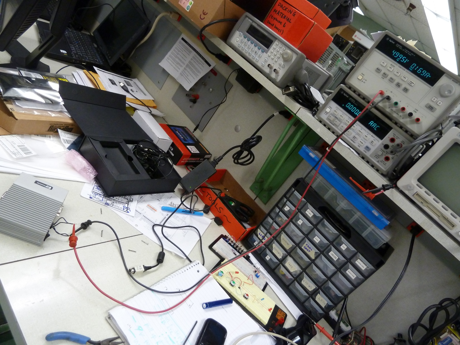
Atom (through USB). So it appears we will be okay power consumption wise! A picture of the setup can be found below.
WEEK 08 SUMMARY
Accomplishments: This week a good amount of tweaks and changes were made to the project. The preparation for the design
review probably was the reason for the many improvements. The Atom board is here now and all of the parts for the PCB have
arrived. The schematic and PCB are almost finalized and not much more work should need to be done next week before submitting
for fabrication. After reviewing the feedback, the team has a clear vision of what needs to be worked on next in the following
stages of the project.
Weekly Work Total: 14 hours
Project Work Total: 59.5 hours
Week 09
October 17, 2011 (4.5 hours) :
The team met in lab after class to continue working on the PCB and power circuitry. Using the schematic on the
datasheet for the LM2596 voltage regulator an initial circuit
was made. With ~9V going in form the battery, 5V should come out and that will power the Atom. This circuit is pictured
below.

When hooked up to the Atom however, a problem arose when it would automatically shut off after
being on for about 15 seconds. After re-analyzing the datasheet, it was realized that some of the wires to the LM2596 needed
to be as short as possible and this helped. Also, once Chuck gave us a breakout board for the non-adjustable version of the
LM2596 (surface mount version that we want to use on the PCB), that was soldered and put into the circuit. Unfortunately this
new circuit was not working correctly. It would produce 5V when the Atom was not connected but then it would drop to about
2.5V once it was connected. This was very strange and caused the Atom to not be able to power up (not enough power obviously).
The plan was to not waste any more time on it and consult the TA's.
October 18, 2011 (4 hours) :
So it was found out that the problem with the regulator circuit was that the inductor was actually a 2 pin device but
had 4 pins, leaving 2 of the pins just for mounting purposes and what happened was they were interfering with the rest
of the circuit in the way they were connected by causing some feedback on the output. So Aditya snipped off the 2 extra pins
and that solved that problem. Therefore the parts were moved to a protoboard where they were soldered to solidify that part of
the schematic and to free up space on the breadboard - see below.
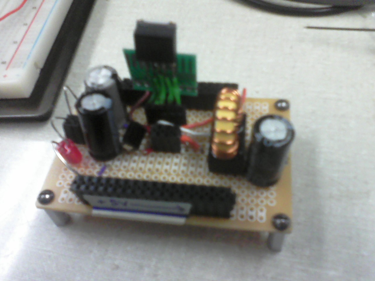
Now that the voltage regulator was
working, efforts were focused to prototyping the BQ24005 battery
charging IC. Using the datasheet again a circuit was made, and it was noticed that the chip got really really hot really fast.
At first it was thought that something was wrong but apparently it is supposed to get hot and its recommended to use a heatsink
with it. The first circuit that was made is below.

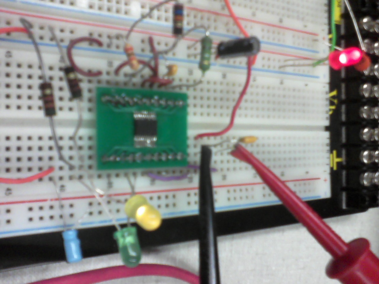
Two LED's were used as 'status indicators' which can help identify when the battery is disconnected, charging, full of charge, etc. And given that they were
not working correctly, it was inferred that something was wrong, but Aditya was not sure what it was. Again help from the TA's
was needed.
October 19, 2011 (7 hours) :
So the only suggestion from the TA was that some internal circuitry in the chip (probably with the input/output lines) must
have been damaged at some point by the amount of power going from Vcc to the battery. In an effort to test that hypothesis,
Aditya and I soldered another IC to a breakout board to see if the same thing would happen or not. After making a more
efficient circuit and adding this new chip the circuit (and LED's) worked as expected! Phew.
Next on
the list to attend to before the PCB had to be turned in was the suggestion by Chuck to design the cooling fans to turn on after
the circuit board got above a certain temperature. We would need a switching circuit, which we found online would be pretty simple
using a 500 ohm resistor and a 2N3704 transistor. That was quickly set up and then added to the PCB design. In reality this could
possibly save a lot of power consumption through the micro because the fans don't have to be on all the time.
October 20, 2011 (1 hour) :
The PCB was finished after Nikhil fixed a few last things including adding a header, clearing footprints from near the
border, and adding the holes for the mounting screws. After all the validity checks passed without any errors, the layout was
ran through the free dfm test and there were no major problems! The board was then printed out and using a foam padding
underneath, the different parts were poked through the paper to prove that all the parts were there and that they would fit
(theoretically).

WEEK 09 SUMMARY
Accomplishments: Prototyped the switching regulator circuit and also the battery charging circuit and they successfully
operate on soldered boards after much debugging. The PCB layout was also completed and the gerber files were generated to submit
for fabrication that will be done by the end of next week.
Weekly Work Total: 16.5 hours
Project Work Total: 76 hours
Week 10
October 25, 2011 (4 hours) :
Spent some time trying to figure out why the 2GB RAM upgrade would not work with the Atom. It simply won't start up with it
inserted but works fine with the stock 1GB - very weird since they are by the same company. The internet did not give any clues
however, maybe a question for Chuck.
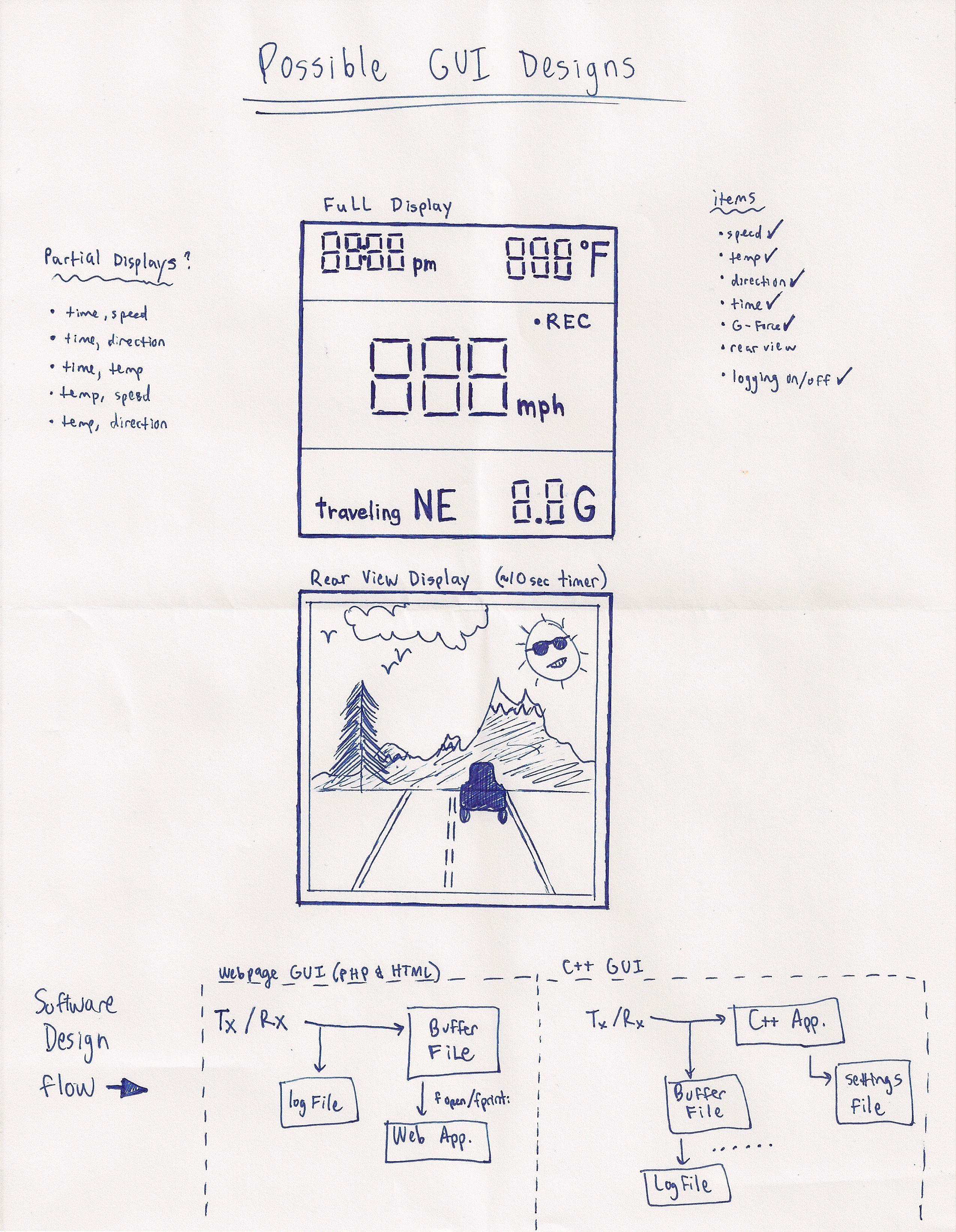
Now that most of the prototyping is complete, we must focus on the GUI aspect of the
project. One interface will be needed for the Atom to Projector communication to display the HUD. The other will be needed for when
the user loads the logged data (via flash) and wants to view the data overlaid on a map. Some notes and GUI sketches that were done
to help visualize things are below.
So first, Aditya thinks that since
we will need to display the feed from the webcam at times that using an HTML/PHP webpage as the way to provide the interface would
be easiest. After efforts to test this way of making a GUI, we found it tricky to display simple text using PHP embedded in HTML.
Once it was realized that a PHP server had to be running, that issue was solved. But at the same time some other senior design
students saw what we were doing and suggested another course of action in regards to providing the GUI. They thought that an actual
application could be made using C#.
To try it out,
Expression Blend 4 was downloaded and some initial
development was started. At first it seems this option might work better since there is a good serial_port library available in C#
which would counter one of the original concerns which was that sending the GUI data serially would be too difficult. Also, the
use of file reading/writing seems easy enough to do and the Expression Blend tool is very robust.
October 28, 2011 (4 hours) :
Met in lab with Aditya to catch up to speed on the GUI development that was done the last few days since I was kept from lab
due to an interview and exams. At this point the major problems were with getting the video stream from the webcam to constantly
show up on the GUI window. Previously he had created the window in Expression Blend because of the useful GUI tools that come with
the software. Then he was editing the .xaml code using Visual Studio because it was easier for him to run/build and he said
Expression Blend was touchy and was "breaking" the code if you tried to change something.
Thirty minutes or so was spent
trying to understand why the code seemed to break when edited in Expression Blend and it turned out that because the operator was
trying to regenerate the video preview while it was still running, then the video stopped all together. Glad we got that out of the
way! Then did some work on creating a mock up gui screen that would ultimately be projected onto the helmet visor/combiner glass.
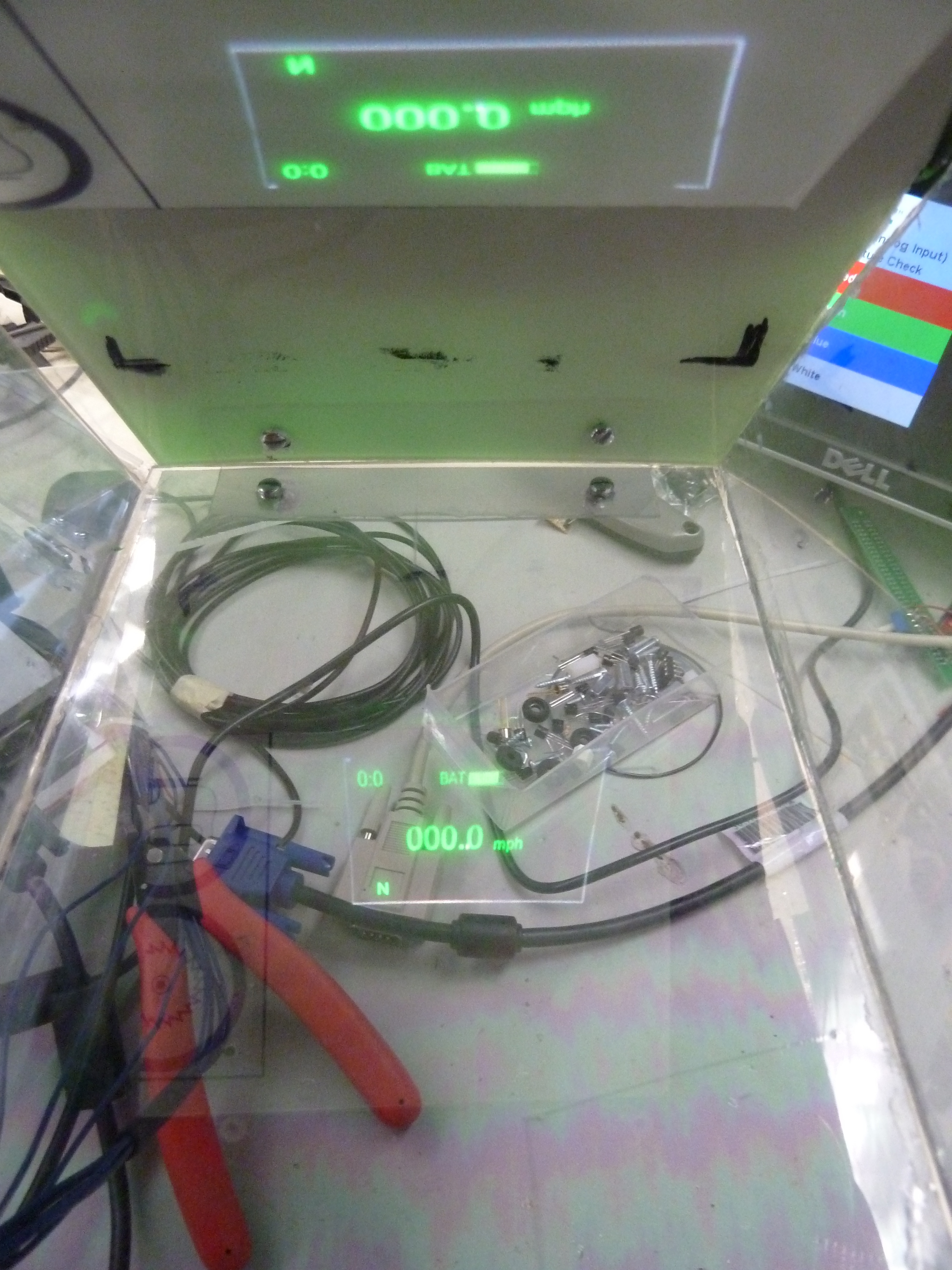
Using different GUI objects and then utilizing the webcam video C# library the following 'screens' were created:
 This is the
telemetry screen view. There are text objects, a progress bar object (battery), line objects, canvas objects, and a button object
(just for now to switch between views).
This is the
telemetry screen view. There are text objects, a progress bar object (battery), line objects, canvas objects, and a button object
(just for now to switch between views).
 This is the webcam view from the laptop's camera (rear view mirror) that will eventually
be enabled via pushbutton and will display for about ten seconds at a time.
This is the webcam view from the laptop's camera (rear view mirror) that will eventually
be enabled via pushbutton and will display for about ten seconds at a time.
 This is the code that was inserted in Expression Blend
into the Button_Click() method. The screen defaults to the telemetry view with a button that says "Video", that when clicked
switches to the camera view that has a button that says "Data".
This is the code that was inserted in Expression Blend
into the Button_Click() method. The screen defaults to the telemetry view with a button that says "Video", that when clicked
switches to the camera view that has a button that says "Data".
Once that was working correctly via Expression Blend,
Visual Studio was used to load the code and then publish it to an executable file. Then that file was transferred to another laptop
where the webcam that will be used on the helmet was connected through USB. Below are the screen shots of the polished GUI being
executed.


WEEK 10 SUMMARY
Accomplishments: A lot of work was done figuring out how to create the GUI and what protocol to use. Then the mock up of the
GUI window was made. Also, the fuel gauge IC was almost completely prototyped and the software for it is working correctly for the
most part. Next week should focus on the PCB construction/validation and the mechanics of the projection technology.
Weekly Work Total: 8 hours
Project Work Total: 84 hours
Week 11
October 31, 2011 (2 hours) :
Stopped by the lab after class and saw that the PCB came in! A quick look-over to validate the hole/pads/routes was done.
Placed some parts on it too to make sure things were going to fit. Noticed that a few things might be cutting it close; the power
connectors for the battery are too big for the holes and might have to be drilled, and the fuel IC and max3232 seem to be too wide
for the footprints on the board so those pins might have to be bent. Discussed with Blaine the order of which it should be
populated:
(1)Power circuitry and battery management circuitry
(2)Microcontroller
(3)Small resistors and capacitors
(4)Everything else!
Then back at home began working on the Patent Liability document which is due for homework this week.
November 1, 2011 (4 hours) :
Went on the internet to research patents/products for the homework and for TCSP presentation tomorrow. Found some products that
definitely are similar to the Incredible HUD but nothing seems to jump out as patent infringement. Based on what was found, made an
outline of the different products/patents and put it on powerpoint. Some more work will need to be done for the report as far as
organizing thoughts and siting sources, etc.
November 2, 2011 (5 hours) :
Met after the presentations when the PCB population was started and GUI testing for serial input began. Using the SerialPort
library, the GUI is able to access the COM3 port that will eventually come from the motherboard but as of now is just from the dev
board. The ouput for testing purposes is just a byte which can be set to whatever number of 1's and 0's from the push buttons on
the board itself. Blaine wrote the code so that it sends out the specified byte when another button is pushed and there is a list
box on the GUI that is set up to recieve the byte from the serial port. After some frustrating work the listbox was able to output
the byte.

Some of the issues were with the semantics of the port being opened and closed and when the ReadLine
was executed exactly. Also the ReadLine was sending in the ACII values of the byte instead of the whole 8 bits separately. Found
out that was because the NewLine parameter for the port was not set and the lines being sent in from the dev board were ending
in "\r\n".
The next step in the progression of the serial capability is having it run continuousl - this will require multi
threading the functionality of reading from the serial port. So far all efforts in getting that working have been futile, and
consulting Blaine or Brian Bowman from team 1 might be necessary.
November 3, 2011 (3 hours) :
Focused efforts on finishing t he patent report.
November 4, 2011 (1 hour) :
Went into lab to check up on the PCB population. Blaine was just finishing up the power circuitry with only minor set backs
here and there. In some new news, Aditya got a mini USB LCD screen from Chuck that was just sitting in the back room and he said we
can have it for our project! Thoughts are that we might use it instead of the projection technology in a way that the image shown
from the screen could be reflected straight into the combiner glass. Also, updated the GUI display to better fit the new USB screen
- widened it and made the video feed bigger and easier to see by the viewer.
WEEK 11 SUMMARY
Accomplishments: PCB population was started this week once the board was delivered. Also, validation was done as more parts
were attached to the board. Serial capabilities were added to the GUI as far as displaying input goes; however, completely
automatic transmission isn't functional yet. Patent analysis was also done this week, and no infringements were found with
existing patents. Continued work on the packaging of the helmet - some more focus on that will come next week.
Weekly Work Total: 15 hours
Project Work Total: 99 hours
Week 12
November 8, 2011 (3 hours) :
Aditya had drilled into the helmet and inserted the webcam. Once that was hooked up to the GUI, it gave a good "rear-view"
picture while someone wore the helmet! See below:

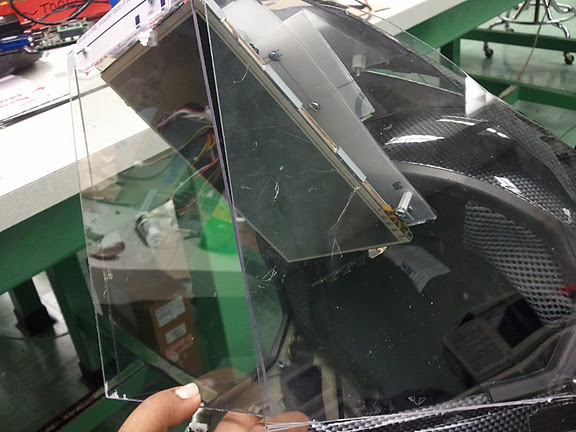
The next step is finalizing the visor. The
material available is fiberglass that was bought online. Chuck has been helping with cutting it and it is up to us to determine
what shapes the pieces need to be cut to so they fit together on the helmet. A single curved piece across the front isn't really an
option since the combiner glass needs to attach to it so a three-sided visor is being conceptualized. However, fitting this new USB
screen inside poses some spacial issues.
Then after talking with Brian from team 1, some new ideas were made on multithreading
the GUI so that the serial port can be read from continuously, aside from other GUI functions. Since there is not much experience
with C# and threading this has been taking some time. Progress has been made but it is still not complete - some exception has been
a roadblock so will consult Blaine when he returns from his trip. So instead spent some time putting capacitors and resistors onto
the PCB near the microcontroller so work to program that can begin.

November 10, 2011 (2.5 hours) :
Went into lab and worked on some of the packaging of the helmet. So far at this point some parts of the helmet have been cut
out and it has been made sure that those parts are not going to compromise the safety or functionality of the helmet. In
particular, the rear view camera was installed into the back of the helmet which caused some of the foam to be carved out. Then
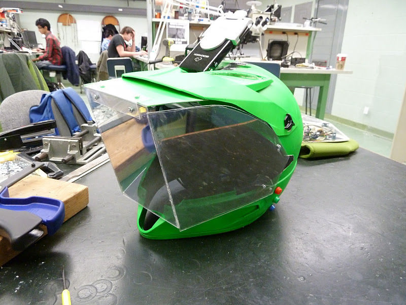
what was worked on today was mostly the creation of the visor. Chuck had cut out pieces of our fiberglass based on the cardboard
cutouts Aditya had previously sketched out. The challenge was then to figure out how to attach the pieces securely. The top piece
easily screwed in to where the original bill of the helmet was positioned. Now there are also side pieces which are fastened by
two nut/bolt mechanisms on each pane. See below for a visual.

WEEK 12 SUMMARY
Accomplishments: More parts have been put onto the PCB. The camera has been put into the helmet and proves to provide a
substantial video feed from its position. The custom visor that will be protecting the user's face and the display technology
has started to be put together.
Weekly Work Total: 5.5 hours
Project Work Total: 104.5 hours
Week 13
November 15, 2011 (3 hours) :
Met with Aditya because after being gone for a few days, needed to catch up on the GUI development. He had found a different
way to create a threading effect for the serial data to be fed into the GUI continuously. Using the C# SerialPort and Dispatcher
objects, the code runs and switches between a textbox and videobox on a press of a button (on the dev board). This button changes
the input from the serial port (COM4) from bytes like '00000000' to '0 0 0 0 0 0 0 0', and then based on that string the GUI
displays a textbox or video feed from the webcam. Now this implementation with the textbox and video feed was made just for testing
purposes to see if the threading could work, and will be put together with the actual GUI esign that has been created already.
Speaking of that design, some time was spent altering it a bit so that it will fit perfectly inside the dimensions of the LCD
screen currently mounted on the helmet. Basically, the labels and such were rearranged and resized to optimally display in a more
'vertical' manner. That new screen setup can be seen below.
November 16, 2011 (3 hours) :
So there were new happenings with the GUI since yesterday - the program breaks randomly sometimes when switching between video
and text. The manner of the problem is simply that the GUI freezes due to the serial port becoming unresponsive. A lot of energy
was spent trying to figure out why it was doing this - Brian from team 1 thinks it might have to do with a thread quitting
unexpectedly and not reopening. But the question is, why would one of the threads be quitting?
Either way, this error seems to
happen randomly - sometimes after running it for 10 seconds, sometimes for 5 minutes. And it seems to fail on both Aditya's laptop
and the tablet PC. So the next idea was to try it on the PC at the lab bench since it has an actual serial port on it, unlike the
serial to USB conversion being used on the laptop setup. This proved to work better and it would break much less frequently if at
all. Maybe the serial port on the dev board to USB connection was faulty then?
Took a few moments with Nikhil to figure
out the conversion for the thermometer - to change the ADC signal from from the micro to degrees Celsius for the GUI. The
thermometer outputs 10mV per degree and is calibrated to output 2.982 volts at 25 degrees. A simple multiplier was figured out and
was added to Blaine's code.
November 17, 2011 (3 hours) :
Today met in lab to figure out more of the semantics with the GUI development. Spoke with Blaine about what bytes exactly are
going to be sent to the GUI. Seems like the micro will send bytes of information from different peripherals at different times
every second. The exact parsing technique will be trivial once the team is at the point where sending functional data to the HUD is
possible.
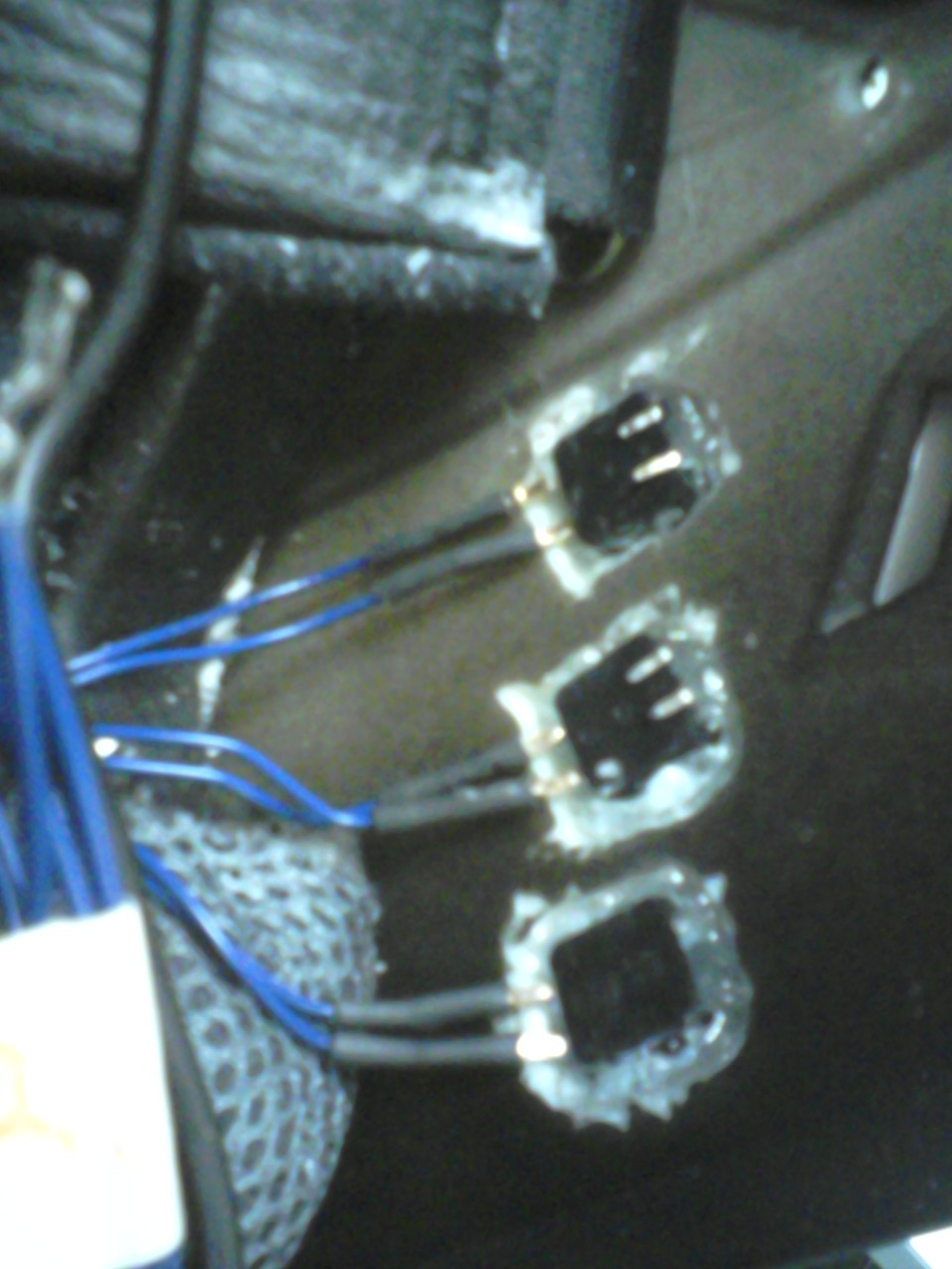
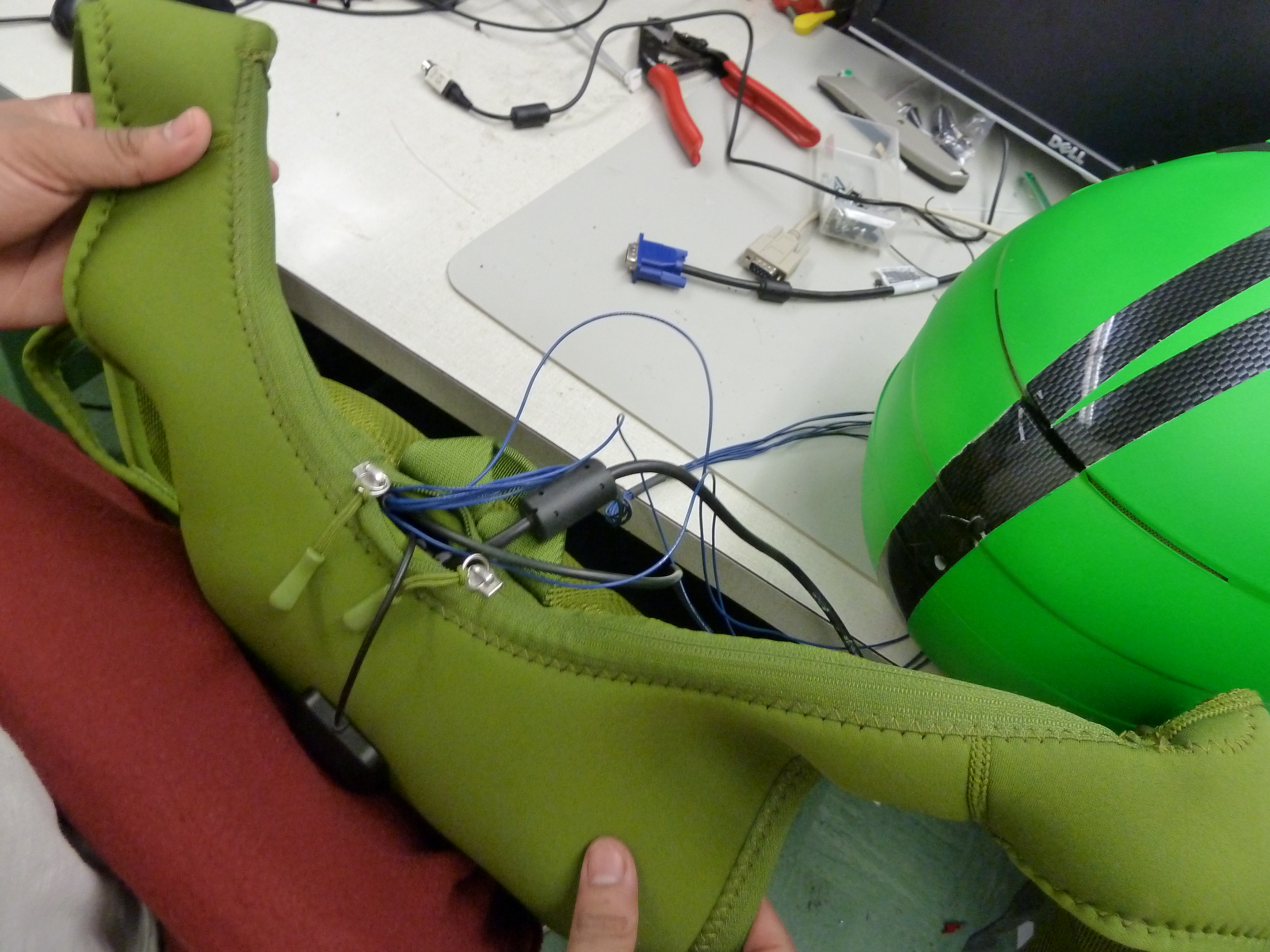
Afterwards, worked on the button mechanisms for the helmet controls with Aditya. This consisted of drilling in the
left side of the helmet and carving out some of the fiberglass so that the buttons are able to be set into the inside and protrude
outward. It worked out really well and the buttons are large so that a user should be able to easily press them with accurate
responses. Please see below for an accurate visual.

Quick note : To aid with the
switching functionality that has been tested the last two days, Blaine wrote a quick loop so that the buttons do not have to be
pressed so many times to see if the code breaks. Also, the windows embedded 7 that was put on the Atom is not able to instal
drivers that are needed to operate the webcam, etc. So a new windows 7 image has been acquired from Brian Bowman and an attempt to
load that was started today but will be continued tomorrow.
November 18, 2011 (4 hours) :
Returned to lab to finish working on the button setup on the helmet. Each button needs two wires to connect to the PCB and
those wires will have to run out the back of the helmet along with the other wires already going there. Using super glue to keep
the buttons in place, the buttons all face the same direction to minimize the clutter near the users face. In the end, there will
be a side pad that will cover these buttons so the user wont even be able to see or feel the wires or backs of the
buttons.
Also worked with Aditya to get the new software running on the Atom so that the USB screen can be
tested with it. There were a lot of system updates that needed to load so that sat there completing those for a while. Once it was
all set, there were some troubles with getting the USB screen to turn on and display the desktop as a second screen to the actual
monitor. It might just have to be ran all on its own - kind of is a pain though to navigate the file systems on such a small screen!
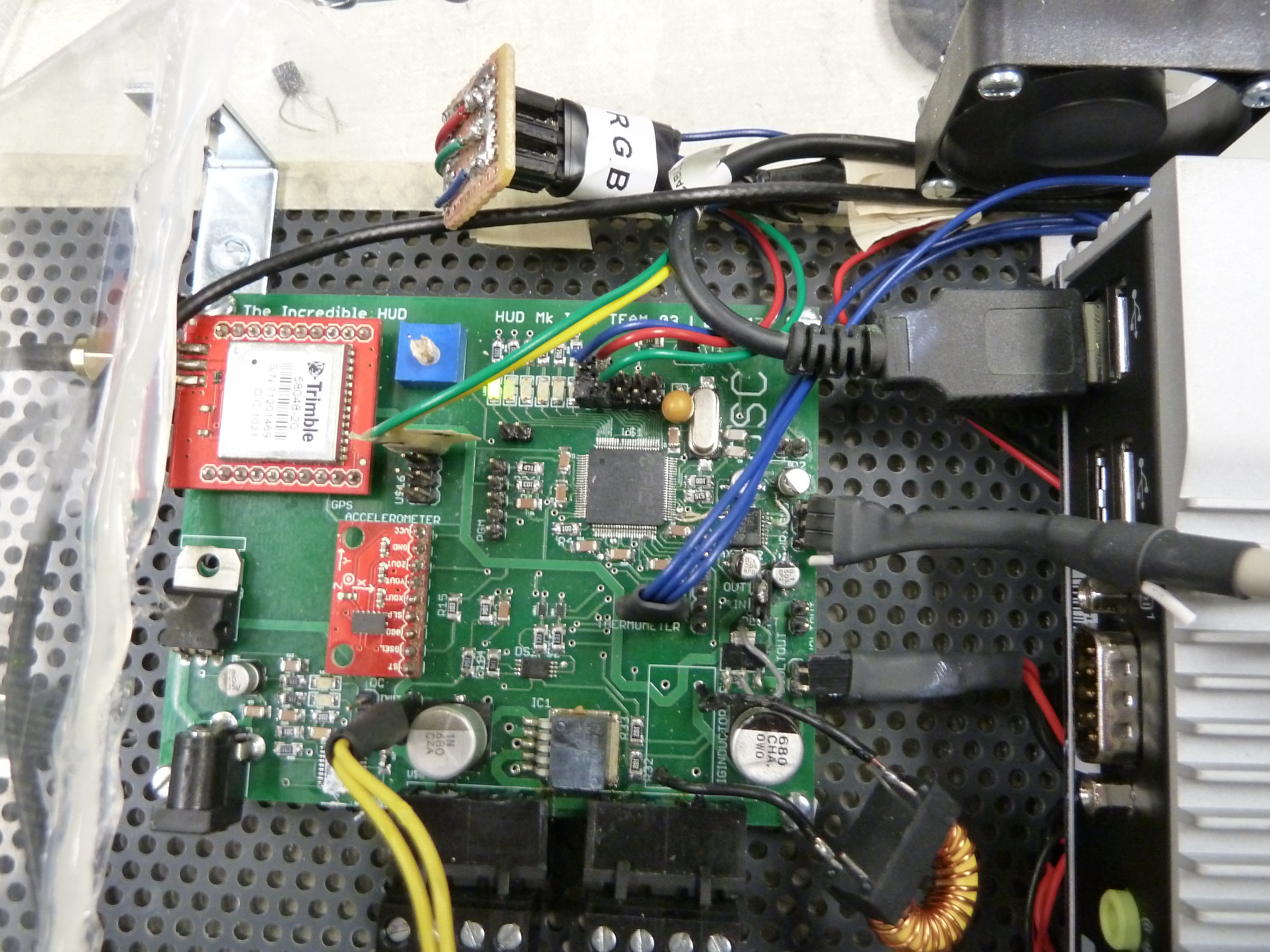
Then sat with Blaine as he was finishing debugging the micro. Now he has finished programming it completely and it runs
smoothly! It can output accelerometer, GPS, fuel gauge, and button data which is pretty awesome. The picture below is of the
completed PCB running w/ the fans on battery power.

November 20, 2011 (3 hours) :
Collaborated with Aditya on testing the USB screen. First, tried running the "switching" version of the GUI on the Atom/screen
setup, and it did not work at all. The GUI would either not open and run (for unknown reasons) or it would open up and then freeze
right away. Now since its known that the GUI worked on the station's desktop computer, we can assume that the GUI is not in error
when testing it on the Atom/screen. So next we tried running it on the Atom/monitor setup and it worked better but not that well
really. The GUI was more likely to startup and run (didn't work overtime) and was less "laggy". However this still was perplexing
because the GUI should be working perfectly!
Troubleshooting thoughts were that maybe the Atom was not fast or powerful enough,
but Aditya assured that it was supposed to be able to handle the GUI. And all the system updates and drivers had been installed at
this point so any missing software being the source of the issue was out of the question. In a last ditch effort we hooked up the
pico projector to the Atom to see if the GUI would operate correctly that way and… it did!
This made us realize that the USB
screen was going to be a bad idea, now for a couple reasons (its slow, heavy, awkward in size). Spent a little while planning out
the new ideas of using the projector again to display the HUD. Used the dremmel a bit to carve and buff out a part of the helmet's
bill so that the projector can sit on the top of the helmet and shine in through the top. Another new idea too that Aditya had was
to implement the diffusor in a way similar to a rear-projection tv; this image on the diffusor will be visible in the combiner
glass to the user. The following pictures can better illustrate what's being talked about:

WEEK 13 SUMMARY
Accomplishments: Got the GUI developed with serial functionality and have almost completely interfaced it with the micro.
Blaine finished programming the micro, with all the components outputting data via the serial connection. As far as the helmet
is concerned, the USB screen was troubleshooted and now the team will go back to using the projection technology to display the
HUD. Buttons were added to the side of the helmet as well. In addition, the Atom has been re-imaged and is completely updated with
all the necessary drivers. The end is in sight!
Weekly Work Total: 16 hours
Project Work Total: 120.5 hours
Week 14
November 21, 2011 (4 hours) :
Reported to the lab because the team was meeting for the "webinar" that was scheduled by the people running the Cornell-Intel
embedded systems competition. After that little presentation, consulted Blaine to get all the information about the different
packets that are going to be sent serially from the micro to the GUI. He set it up so that the accelerometer data will start with
"Accel ...", the battery data with "Batty ...", the GPS with "GPSLN ...", the thermometer with "Avges ...", and any buttons with
"Buttn ...". Each packet has corresponding data (numbers as ints or floats). So the job at hand is to make an algorithm that will
process and parse the incoming packets to then update the GUI labels and thereby implementing the HUD display. At the end of the
day, got most of it working properly. While inside the lab, only the G-Force and Temperature were able to be updated because the
GPS needs a satellite signal to be able to get Speed, Altitude, Time, and Direction data. But at this point, it can be assumed
that they are functional. What needs to be finalized though are the Buttons and the Battery Gauge - need to partner with Blaine
to interface the buttons on the helmet with the micro, and for him to validate the fuel gauge output.

WEEK 14 SUMMARY
Accomplishments: GUI implementation with the serial data was started. More work/debugging will most likely be needed once
the system can be tested with a valid GPS signal. Will continue after thanksgiving break.
Weekly Work Total: 4 hours
Project Work Total: 124.5 hours
Week 15
November 29, 2011 (3 hours) :
Returned from break to work on the packaging todo items. Aditya had Chuck cut out some pieces of acrylic for the backpack unit
the day before. Using a gray perforated acrylic that Aditya had bought online as the base of the unit, the clear acrylic pieces were
attached to it (through the holes) using brackets and small nuts/bolts. This seems to be generally pretty stable and should make a
robust enough case for the backpack unit.

As far as the helmet visor goes, the fiberglass pieces were attached to it and
just need a way of sealing all of the edges. Will have to see if silicon or superglue will work best. Before that began however,
the thermometer was taken off of the PCB (it was soldered on there mistakenly) and was broken out. What that means is the pins were
individually soldered to wires and shrink wrapped. Then a hole was drilled through the back of the helmet, slightly above the webcam hole,
so that the thermometer can poke out of it. The reason it should stick out the back is to protect it from wind and debris while still
giving an accurate temperature reading. This will then be connected to the pcb through a header.


November 30, 2011 (3 hours) :
So the new industrial compact flash card that Chuck ordered for the team came in. Aditya booted up the Atom with this new card and
was able to successfully get the operating system to run and all of the drivers to get loaded. In attempt to test the GUI on the Atom
a published version of the project was loaded and installed onto it and unfortunately whenever we ran it, the program crashed. This problem
continued to occur within 10 seconds of starting the GUI. Assuming that the Atom could handle the processing necessary to run just the GUI,
it was not clear what was causing it to crash. The only thought was that it could be the Webcam part of the GUI. Within the code there was some
overhead to implement the webcam software and so all of that third party code was removed, leaving just the code we had written up to this point.
After that modification the GUI ran somewhat well on the Atom - it still randomly crashed here and there but when it did run successfully, it
would run for long periods of time (1.5 hours later that night). Further investigation will be necessary if the webcam is to be implemented in
the future.
December 1, 2011 (3 hours) :
Went to wallmart to buy some more hardware pieces for the backpack unit. Once in lab, installed the front panel securely, and then added
hinges to the top cover. For this, had to drill holes into the top and side panels which was tricky because the acrylic in itself is very fragile.
Also added a magned clasp to the other side of the cover panel. All in all, the unit is now accessible through a magnetic door!
In an attempt
to then seal all of the edges of the box, used a combination of silicon adhesive and super glue to layer over all of the gaps. Once it dries, it
should be able to be slid into the back pack with only the "top" (back) of the box open to allow the cables to connect to the helmet.

In addition, green spray paint and primer were bought at wallmart for styling the final helmet. Using some 220 grit sand paper to slightly
rough the surface of the helmet, the primer and green paint should easily adhere.
December 4, 2011 (5 hours) :
Went back to the GUI after test running it outside and finding that the altitude and time weren't quite working. Spent some time double checking
what packets were actually being sent through serial and then checking that what was getting parsed was in the right format. Turns out that the
altitude was preceeded by many zeros and so thats why it was only showing "+0 ft". Also, the time was coming in as GMT and wasn't parsed quite
correctly because of some double to int casting (which was wrong). So instead decided to use a different packet to get the time information.
The
next task was to write the code to do the data logging. This was a task in itself. Based on the .kml file that Aditya aquired from Google Earth, the
semantics of the data in the file were figured out. There were many lines of "header" info, followed by the actual data points, followed by "footer" info.
So in the GUI code, wrote an algorithm that would create a new file with the header info (on the thumbdrive connected to the Atom) whenever the 'Log Data'
button was pressed on the helmet, and then for every data packet that would get displayed to the GUI, it would also save that as a geographical point
with corresponding data, consecutively into the file (as long as data logging was enabled). Then once the 'Log Data' button is pressed again, the
file would write the footer and close. In theory this worked except for one exception which Blaine later found out was trivial String type
semantics in regards to the file names.
Then to help eliminate any glare from outside light, made some fiberglass pieces to cover any holes and gaps
in the bill of the helmet. Simply stenciled them out and cut them to size. And then primed them and spray painted them green so that they look like
part of the helmet.
WEEK 15 SUMMARY
Accomplishments: GUI was tweaked, and data logging was created. The backback unit was constructed, along with the visor on the helmet, which
was later painted. Blaine used auto hot key to automate the published GUI when the Atom is booted up. First tests outside were done which will lead
to more changes. PSSCs are almost ready to be demo'ed.
Weekly Work Total: 14 hours
Project Work Total: 138.5 hours
Week 16
December 6, 2011 (5 hours) :
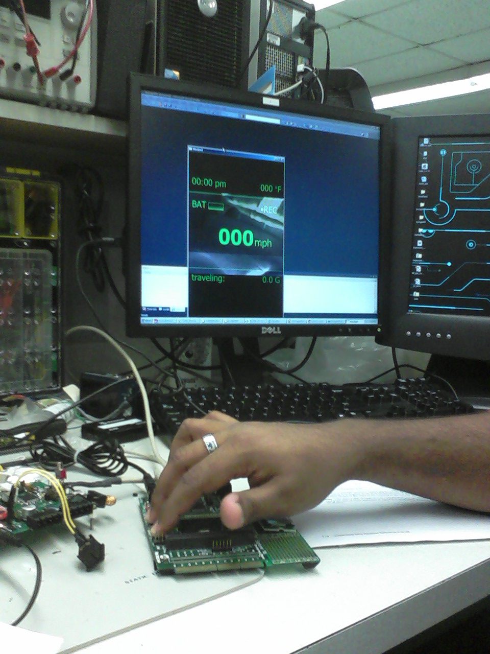
At this point most of the PSSC's had been demo'ed. More time was spent figuring out why the GUI wasn't completely working and displaying the
correct data. Had to compare to Putty and validate that it was recieving the correct packet information, which it was not (for the battery info).
So Blaine fixed it and reprogrammed the micro. This proved to not help the GUI what so ever. Eventually, decided to increase the buffer size for the
serial data to 4 times its usual size. This helped some, but not completely. Finally, it was noticed that there was a strange and unnecessary function
call that was our guess as to what was not working with the rest of the code.
After that, the battery needed to be charged and so used the battery
charging IC. However, this failed at random points and kicked back in when the power cycled back which was very peculiar. So we ditched that and just
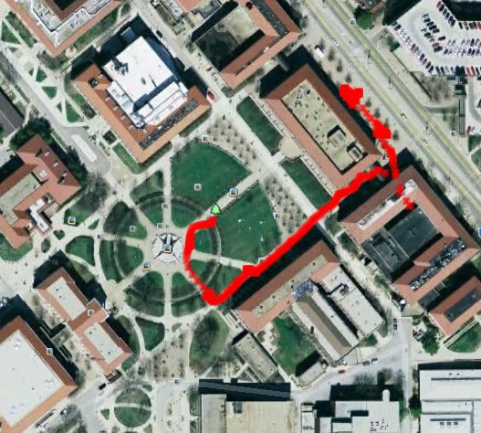
charged it from the wall. Then we took it out for a test run. Putting on the back pack and the helmet, we walked around Engineering mall and by
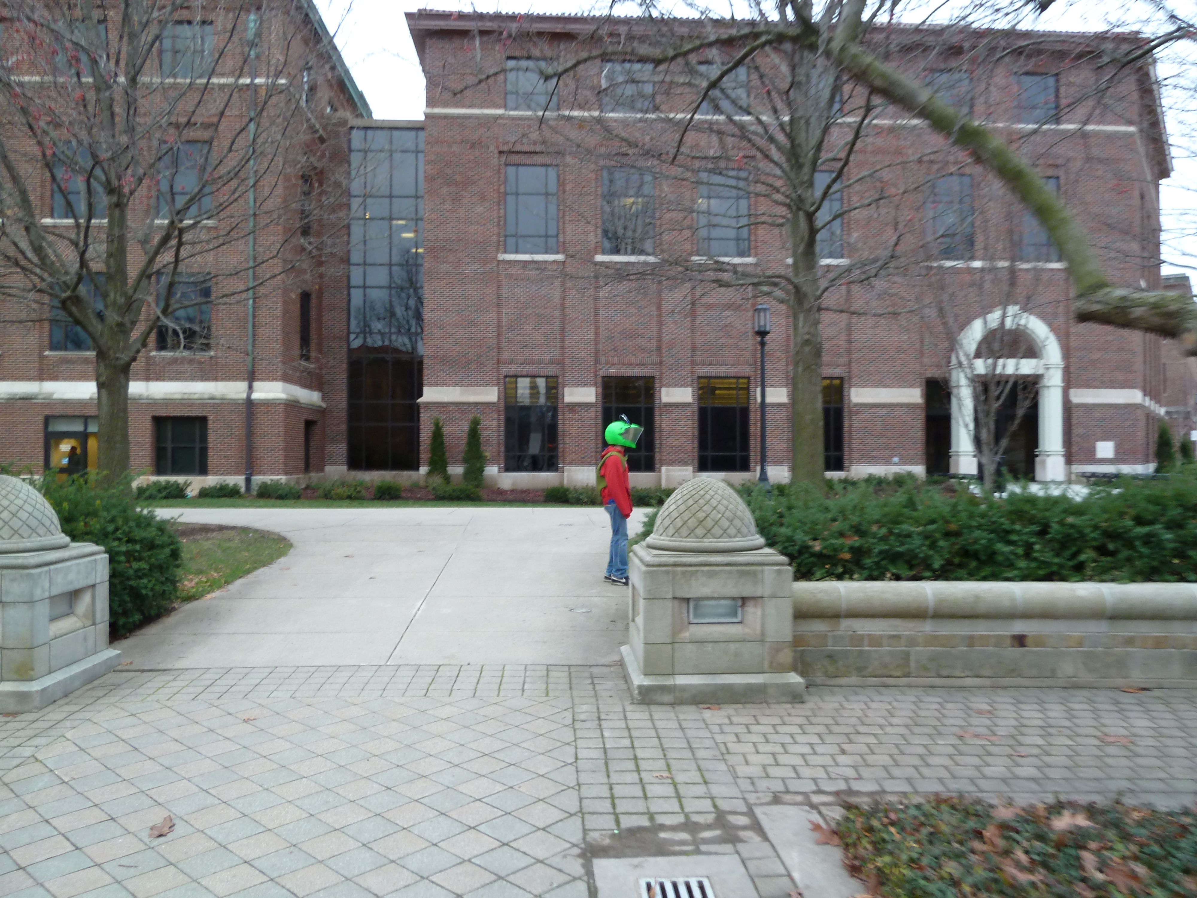
Northwestern Avenue to check all of the telemetry readings. The GPS takes about 30 seconds to kick in but once its running the system performed very
well. See below for snapshots of the test and the painted helmet:

December 9, 2011 (3 hours) :
Made a video to help demo the HUD for when the team later presented to the 362 and 270 classes for bonus credit. Then spent some time in lab updating
lab notebook and completing the peer review.
December 10, 2011 (4 hours) :
Worked on the final report and other documentation with Aditya and Blaine in the lab.
December 12, 2011 (6 hours) :
Finished and submitted all final documentation in lab. Later on, worked on the final presentation powerpoint.
WEEK 16 SUMMARY
Accomplishments: Finalized the project packaging and GUI. Thouroughly tested the HUD outdoors. Completed all final documentation for submission.
The project is finished for this semester!
Weekly Work Total: 15 hours
Project Work Total: 156.5 hours