Brandon Blaine Gardner's Notebook
Week 01
August 23, 2011 (1 hour):
Met as a team after class to discuss preliminary project proposal.
August 24, 2011 (1 hour):
Drafted up a very quick sketch in class of what our project might look like when finished. Met as a team after class to finish writing preliminary project proposal.
August 25, 2011 (1 hour):
Spent some time making a more detailed drawing based on the quick sketch I made.

In addition to the sketch, the Google Code site to help organize team ideas as well as a facebook group. The link to the GCode site is <http://code.google.com/p/the-incredible-hud/>.
August 26, 2011 (1 hour):
Met with Aditya and Dr. J to discuss his thoughts about our initial design. Some thoughts during the discussion are to follow:
* Make sure all controls needed during use are on the left side of the helmet so that use of throttle is not impeded.
* Make sure the case for the unit containing the GPS chip is NOT metal (Faraday cage).
* Make sure the device will function in a wide temperature range.
* Audio feedback on the helmet? Discuss this with team further.
* May be wise to NOT dismantle the projector, as previously discussed in favor of not risking breaking a $300 integral part of the project and instead taking care to make note that it is possible but that we are not doing it for this reason.
* May be able to get financial assistance from Intel if we use an Atom board, and Atmel/TI may be willing to help also; none of the aid is guranteed, and it will likely mean the project will be kept by the university.
August 27, 2011 (1 hour):
Looked at Atmel ARM and Intel Atom motherboards for our design. Sent a couple emails about the ARM boards that looked good, and Dr. J sent the team a PDF about finding the right Atom board. The team will discuss these next week. Also researched potential HUD projectors. The Pico projector discussed previously keeps coming up in the internet searches, so this seems like a good option.
WEEK 01 SUMMARY
Accomplishments: Submitted preliminary project proposal; sketched initial design; researched motherboards and projectors.
Weekly Work Total: 5 hours
Project Work Total: 5 hours
Week 02
August 30, 2011 (2 hours):
Met as a team to formulate PSSC and develop preliminary block diagram for presentation in class on September 7. Motherboard choices were also discussed. Aditya brought up an interesting idea: a netbook could be used as the main (backpack) unit of our design easily. It offers a screen for development, a long-lasting power supply (battery AND charger), small-size, reliability, and is easily exchanged for an Atom-powered board at a later date to decrease the potential size of the overall design. Commercially available cameras (with good drivers) could be used for IR and rear-view cameras if we wish to implement them. It would also be very easy to use a script to (with an internet connection) parse logged data to (for example) post trip details to Google Maps.
August 31, 2011 (1 hour):
Looked up accelerometers for use in the helmet. Sparkfun has many good options, and the pricing is from $15 to $30 depending on the unit. Some have RS232 ports, some are on breakout boards (VERY NICE!), and some are in VERY tiny individual packages. The human body can withstand +/- 4 G's without passing out; this seems a good lower limit for the sensitivity of the accelerometer unit. The ADXL203 is great, but it is only 1.7 G's. The MMA7361 is better, but it requires 2.2v to 3.6v for operation; this may mean trouble if the other components use 5v. The ADXL320 is perfect (and only $14) but it has no breakout board and will be hard to mount; two to three would need to be ordered (sampled) in case of breakage or problems attaching to the PCB. Updated Google Code wiki with accelerometer links.
September 1, 2011 (2 hours):
Met as a team to finish the final project proposal.
September 2, 2011 (1+1=2 hours):
Met with Dr. Johnson to discuss funding for an Atom motherboard and possible extra funding for the project to demonstrate Atom functionality; this may provide resources to buy much better display technology as the projector (as suggested by initial testing) will likely lack brightness. Chuck Barnett was given approval by Dr. Johnson for the purchase of an Atom motherboard for the project.
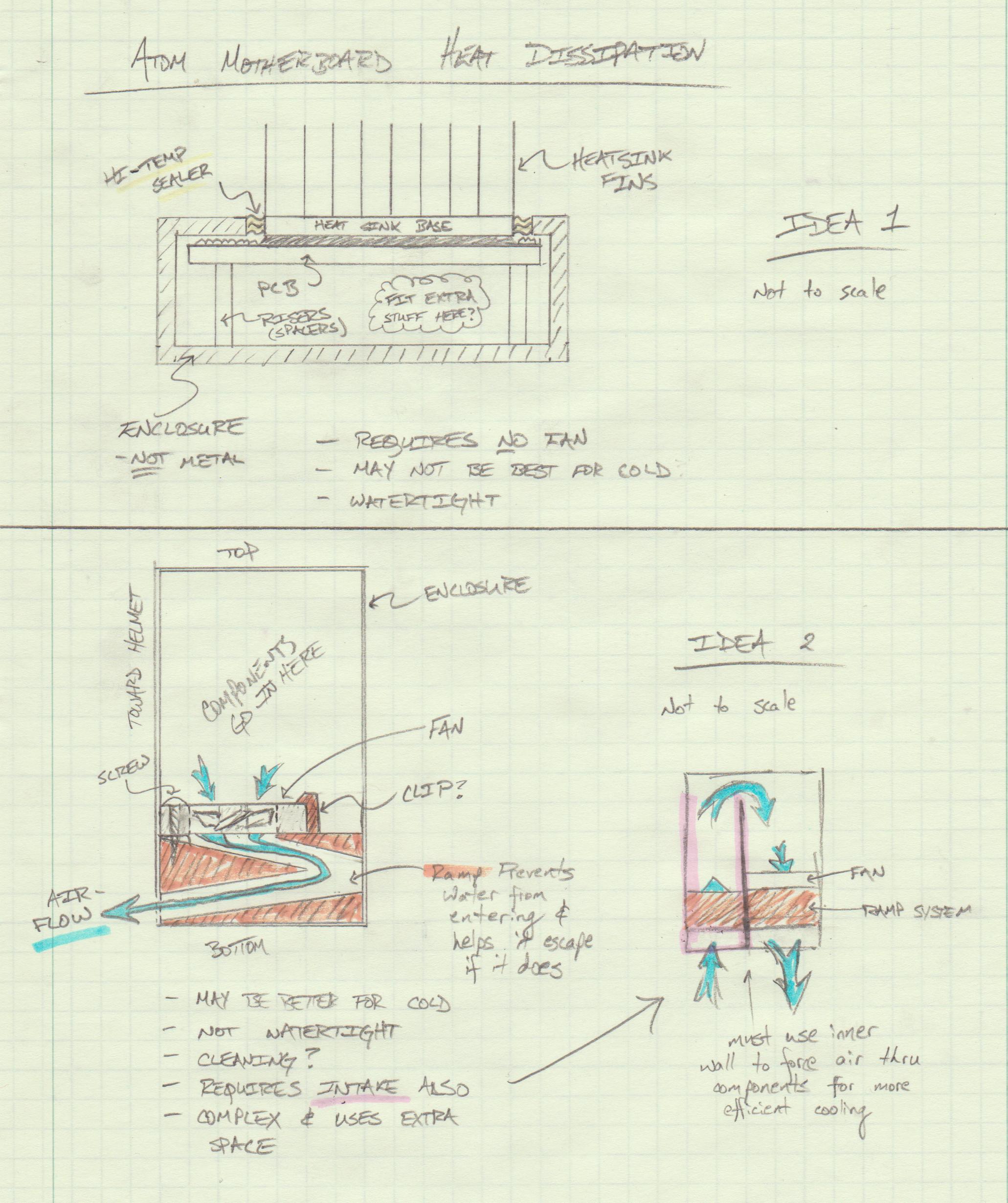
Heat dissipation for an Atom motherboard was also discussed; a few ideas talked about are demonstrated on the scan below. Johnson also found favor with an idea to use a netbook's battery and its power regulator circuit as well.
(Thought: Will this include the charging circuit also? A charging feature would be impressive but may be very complicated.)
WEEK 02 SUMMARY
Accomplishments: PSSC and project proposal finalized.
Weekly Work Total: 7 hours
Project Work Total: 12 hours
Week 03
September 3, 2011 (.5 hours):
Updated wiki with links to PIC-32 microcontroller search and Intel Atom Pico-ITX motherboard search.
September 6, 2011 (2.5 hours):
Met as a team to finalize design presentation of PSSCs for Wednesday and created parts library for PADS tutorial.
September 7, 2011 (2 hours):
Completed PADS tutorial from course laptop.
September 8, 2011 (5 hours):
PADS tutorial checked off by course TA. Sampled three PIC32MX564L-I/PL devices from Microchip; expect these to arrive in 1-2 weeks. Researched tilt-compensated compasses; design considerations below:
* Calculations for the compass are dependent on a ~1G normal force detected by the accelerometer; this means that while moving, the calculations will be invalid.
* The efficient algorithm for the tilt compensation is called CORDIC.
* Some of the more expensive ($150+++) units may have better algorithms, but it seems unlikely.
* George, the course TA, suggested researching IMUs, which integrate a gyroscope; solutions including compass, accelerometer, and gyro range from ~$60 for units with no on-board calculations to ~$130+++ for units that process the data on-chip (the output format of the data could not be determined by datasheets; it may simply collect the raw data and transmit to the user).
* The algorithms for compensating for tilt and speed for a compass using an IMU seem fleeting and esoteric.
* Since it is possible to use GPS data and extrapolate direction based upon movement without the need for complex, computation-heavy algorithms, it seems best to calculate direction by filtering GPS coordinate data.
* A paper published by the Honeywell corporation found online seems to suggest that it is possible to waste time (1000s of man-hours) developing a compass correction algorithm; the PDF can be found here. Excerpt:
"Digital compass firmware is not a task to be attempted by novice designers with quick design times in mind. In most cases, hundreds to over a thousand hours of firmware development and testing are expended to create a successful compass routine."
* It would still be possible to use a compass in our design while the user is (nearly) motionless, it seems a redundant feature; discuss this further with team and professors.
Aditya will be placing the order for the following accelerometer: MMA7361. It offers +/-6g measurements, very close to the ideal +/-4g range (this is the range an average person can withstand before beginning loss of consciousness), as well as 3.3V optimal voltage supply (the same voltage as the microcontrollers and other components being considered).
September 9, 2011 (3 hours):
Met with Aditya and Chuck Barnett about ordering an Atom motherboard. Orbit Micro (.com) offers a 1.1 GHz Pico-ITX form factor board with a passively-cooled case, 4 USB ports, 1 COM port, audio out, power, and an 8GB bootable flash chip. It is quite small, and should meet the needs of the project very well. Link
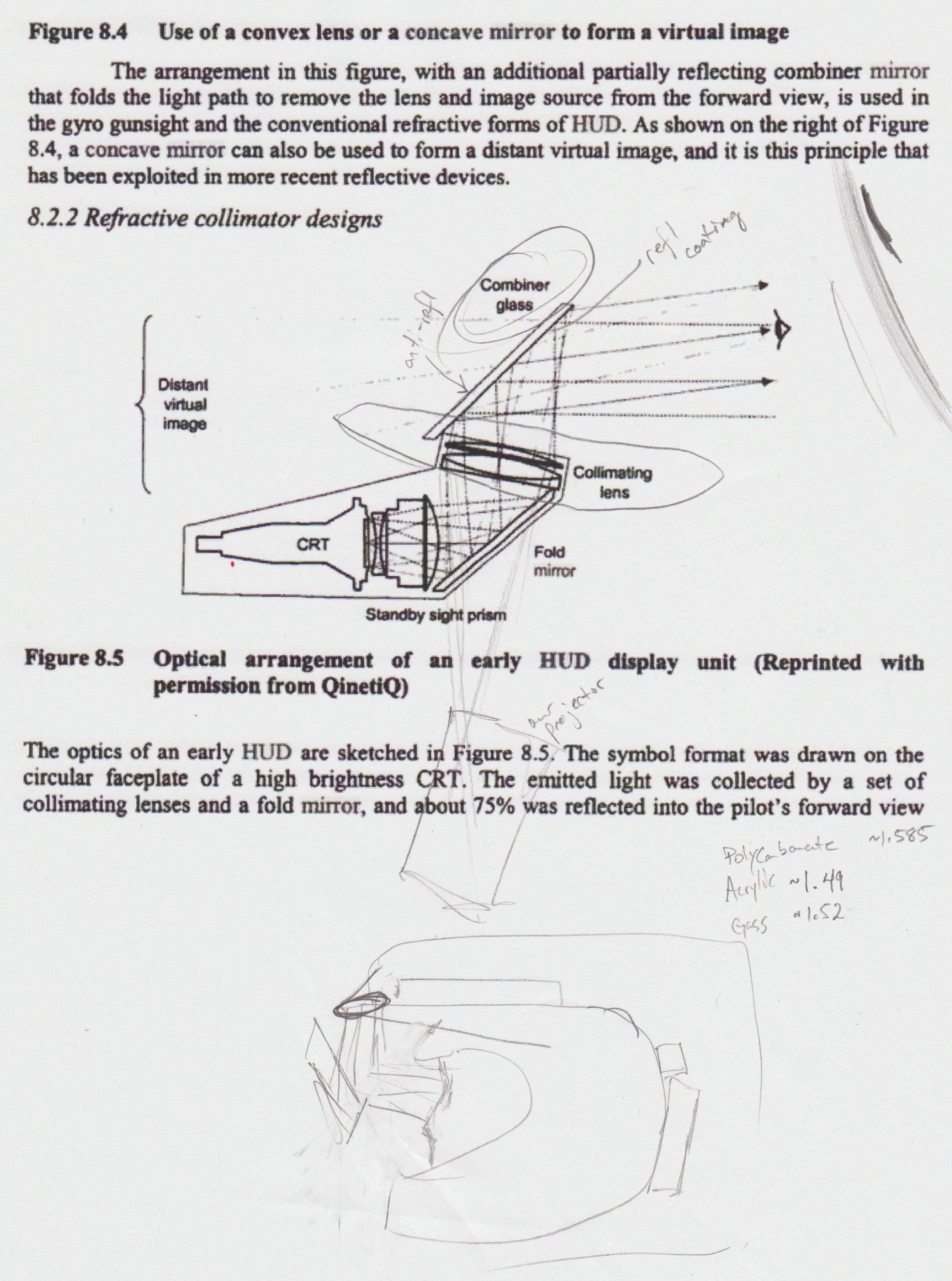
Possible methods of making the HUD appear at a distance were discussed as well after reading a few technical documents. It seems that a "collimating lens" may be the solution to the problem. Professional insight will likely be needed to determine the best case of action. Below is a diagram from a book found on Google books featuring a sketch for a HUD system in an aircraft with pencil sketches and notes from the discussion.
WEEK 03 SUMMARY
Accomplishments: Accelerometer, PIC32s ordered; plan of action developed for distant HUD projection (collimating lens).
Weekly Work Total: 13 hours
Project Work Total: 25 hours
Week 04
September 13, 2011 (4 hours):
Worked on HW3 Calculations section, microcontroller-level block diagram, and top-level block diagram. Six samples (instead of the expected three) of PIC32MX465F128L microcontrollers arrived today.
The purchase of a LiIon battery for powering the Atom motherboard was discussed and seems the logical choice for powering the system. During this discussion
Aditya also suggested using USB to power the microcontroller and telemetry sensors versus a commercially available battery (e.g. - 9V); this idea was extended to also providing power via USB to the Pico projector. Rationale for supporting these decisions is that if the user has only one battery to manage, the product will be much easier to use than if three were needed. It should now be discussed whether the LiIon battery should be recharged from a standalone charger or whether the helmet should have a power connector for recharging the battery. Arguments for the standalone charger include weight-saving and ease of implementation. Arguments for the integrated charger include the ability to use the helmet indefinitely as long as it is sourced with power.
The final topic of discussion was the details of the messages to be sent from the microcontroller to the Atom board.
The proposed format would be similar to the following:
<latitude> <longitude> <altitude> <direction of travel> <ground speed> <vertical speed> <temperature> <button presses>
The 'button presses' field would likely be a simple vector of zeros/ones (e.g. - 0100000 means the button 2 is pressed).
September 15, 2011 (4 hours):
Met as a team to review and finish the HW3 document.
A PIC32 Development Kit (Explorer 16) was checked out from Chuck Barnett. The software and drivers needed to program the kit were not able to be installed due to administrative privileges on the team's desktop computer.
Time was also spent brainstorming methods of mounting components onto the helmet and how best to waterproof and ventilate those components.
September 16, 2011 (6 hours):
Preliminary testing of shining the projector on to plexiglass with car window tinting on either side was shown to be marginally effective. Combiner glass will likely be the best option for the projection surface.
After being given admin privileges on the desktop account, PIC32 development software and drivers were able to be installed, and work began on testing the I/O functions of the dev board and PIC32.
In the evening, a simple sample piece of software was finished utilizing three pushbuttons to control the display of eight LEDs. The next logical step with the board will be AtD functions, which will be able to be tested using the on-board potentiometer-based voltage divider on the Explorer 16.
September 17, 2011 (3 hours):
AtD functions were tested on the Explorer 16 by illuminating a percentage of the total LED strip in accordance with the level of a potentiometer.
WEEK 04 SUMMARY
Accomplishments: More details nailed down; Explorer 16 Development board works well; I/O and AtD functionality demonstrated successfully
Weekly Work Total: 17 hours
Project Work Total: 42 hours
Week 05
September 19, 2011 (8 hours):
UART/RS232 functionality was tested on the Explorer 16. The GPS, which communicates via serial, was then connected to the computer to test its functionality. The GPS related only garbage data to TeraTerm and PuTtY, and the Trimble Studio software used to interface with the GPS chip was recording no input.
September 20, 2011 (9 hours):
The Trimble Studio software was able to communicate with the GPS successfully after using the Explorer 16 as a translator. It is likely that the communication issues from GPS to PC were caused by a line-level issue. Since our PIC will be interfacing with the GPS in the final design, this not a problem.
The Explorer 16 was used as a translator like so:
PC <---> Explorer 16 <---> GPS
After the GPS was successfully tested, one of the six PIC microcontrollers sampled was soldered to a breakout board provided by Chuck. This was extremely difficlult, as the PL package was chosen instead of the PT package: though the PT package is more expensive, the pins are larger and wider-spaced than the PL package, which has ABSOLUTELY TINY .4 mm pin spacing.
September 21, 2011 (2 hours):
Decoupling capacitors and an 8 MHz oscillator were soldered to the microcontroller breakout.
Programming specification datasheets were found to aid in circuit design. A Development Tools Design Advisory for the ICD 3 was found which detailed potential programming/debugging issues. This ICD3 Modification OR the use of a 10kOHM pull-up resistor is suggested as a fix. Figure 4-2 of the PIC32MXxxx Programming Specification details the low-ESD capacitor needed from Vcap/Vcore to Ground. Figure 2-2 of the microcontroller's datasheet was used as a reference for the capacitor locations (Figure 1-1 of the Design Advisory above disagree as to the placement of the 470-OHM resistor; however, the datasheet's Figure is much older than the advisory's).
September 22, 2011 (8 hours):
Ground and 3.3V connections were made to the microcontroller, as well as an ICD 3 programming header. The MPLAB IDE and the ICD 3 were not initially able to recognize the device. The culprit was eventually found to be a mis-soldered 47uF bulk capacitor.
It should be noted that the device is able to be programmed successfully by following the !MCLR pin pad interface detailed in Figure 1-1 of the Design Advisory.
Note: Starting September 23, a camera will be readily available to allow for better documentation.
September 23, 2011 (1 hour):
Developed the following schematic for the PIC based upon the needs of the project and the work spent soldering the breakout board.

As stated in the note from Sept. 22, the camera was used to document the current development environment of the PIC breakout board.

A closer look at the breadboard and breakout were also taken.

WEEK 05 SUMMARY
Accomplishments: GPS interfaces with PIC, but no translation has been programmed; PIC is soldered to breakout board with capacitors, oscillator, etc.; the breakout can be programmed
Weekly Work Total: 28 hours
Project Work Total: 60 hours
Week 06
September 26, 2011 (1.5 hours):
Using the UART/RS232 code from the Explorer 16 development, the PIC breakout was programmed with UART interrupts to facilitate communication from GPS to Micro and from Micro to Motherboard. A timer was also implemented but was fairly trivial. There are to be only three buttons on-helmet and five available external interrupt pins on the PIC. The external interrupts will likely be used for button presses and the timer used for debouncing.
The updated breadboard layout follows.

The underside of the PIC breakout is shown below. The large solder-bridged section is an improvised ground plane, and the programming wires to programming channel 2 have been cut.

September 27, 2011 (9 hours):
UART communication issues were the issue of the day. It was found that a line-level driver for RS232 was needed in order for the PC to receive proper input from the microcontroller; the line-level converter was also used to test GPS communication directly to the PC, proving the previous issues from Sept. 20 to indeed be line-level issues. It was also found that the UART interrupt flags need to be cleared *after* the buffer data is read; this was not necessary on the Explorer 16. It is unclear whether this is because of the processor design or because of some other issue. A wait timer was also required (~3 seconds) before startup to get rid of UART communication glitches. The reason for this is unknown, but it is suspected to be a result of having to move all decoupling capacitors and other minimum connections so far from the microcontroller itself due to the breakout board's layout (see above image from 26 Sept.).
After the UART modules were successfully working, the Trible Studio communication program from Sept. 20 was recreated using the PIC breakout. Below is a picture of the Trimble Studio program communicating with the GPS using the microcontroller as a translator.

The UART connections at this point in the prototype are shown below. Notice that masking
tape is being used to identify all connections for easy debugging and translation to the
PCB design. The LEDs are also marked. The black breakout to the right of the GPS is the line-level driver given to us by Chuck Barnett. The chip is quite outdated and introduces periodic ground noise into our circuit on the top ground rail. Attempts to fix the issue were fruitless, and it was eventually decided that the noise was not of the same frequency as any of our components and poses no real problem; the chip will be replaced with its successor in our final design, hopefully getting rid of these issues. It was found the microcontroller's ground connection (made from the top ground rail) is noise free, likely due to the decoupling capacitors. Capacitors were added to the top rail to clean the noise, but it is mostly ineffective.

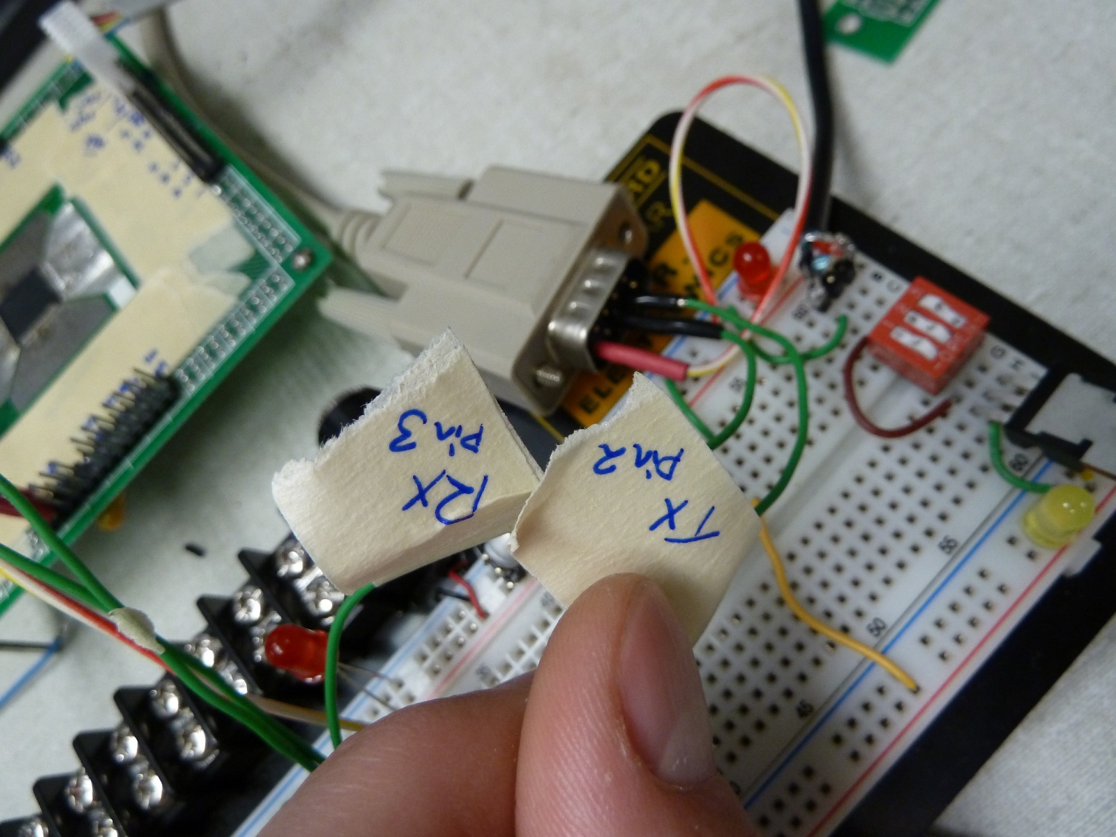
For future reference, the UART connections to the PC are shown below as they have been a source of confusion many times. The Tx line is transmit data FROM the PIC. The Rx line is receive data INTO the PIC. The pin numbers represent the pins on the male RS232 connector.
September 28, 2011 (3 hours):
After the UART demo was created, the code began to look cluttered, so time was spent to clean up the code. After the code was cleaned up, the ADC initialization code was written but not tested.
September 29, 2011 (6.5 hours):
An hour was spent going through the ADC documentation thoroughly. The ADC initializations were rewritten and tested. The ADC was reporting an endless stream of interrupts until it was discovered online that the input buffers MUST BE READ before the interrupt could be cleared; this was not clear in the documentation. After this issue was corrected, the ADC was able to be tested successfully.
The image below shows the new connections made between the accelerometer and the PIC. Masking tape is still being used to document the design. Also notice that ground from the bottom rail is being used for the accelerometer due to the noise from the RS232 line driver.

September 30, 2011 (5 hours):
The accelerometer data was sampled and collected to yield test data. The method and data collected are described in the code comments, copied below.
/*
Data was collected using the average of a number of
X, Y, and Z points placed approximately in such
a position to give 0, -1, and 1 g measurements
for each. Four 0 g measurements for each axis
were acquired and 1 measurement each of -1 and
1 g. The zero-position measurements were
averaged to achieve the data below. The
average difference between zero and +/-1 is
given as delta. The overall average delta is
given afterwards. This should give a good
approximate measurement of g-force overall but
will not be perfectly accurate in all settings.
Data collection results:
X(0) = 512.225 ; delta = 63.95
Y(0) = 524.15 ; delta = 64.25
Z(0) = 495.45 ; delta = 62.7
Delta avg = 63.633
Now create a linear model based upon the data.
*/
WEEK 06 SUMMARY
Accomplishments: UART tested successfully on prototype; ADC tested successfully on prototype; accelerometer linear model data taken
Weekly Work Total: 25 hours
Project Work Total: 85 hours
Week 07
October 4, 2011 (9 hours):
The accelerometer linear model was programmed to the micro for converting to g-force measurements. The model was successful, varying by only +/-0.1g. A pushbutton was also implemented to test button inputs; the purpose of this button was also to simulate the 0-g detect signal arriving from the accelerometer. External interrupts on the rising and falling edge (change notification interrupts) were implemented; however, a bug in the PIC's hardware will miss up to 25% of the interrupts. Timer 1 was set to interrupt at 100Hz and was used to get button input. After the PIC was successfully reporting 'hang-time' spent under 0-g conditions, the code was updated to revision 0.2.0. See the image
below for a picture of the new setup.

Time was also taken to clean up the code. All PIC peripheral functions and methods were moved to headers. The only code in the main file is code for the main loop itself. This hugely improves readability of the code and allows for more comments without cluttering the code. The shiny clean code was updated to revision 0.3.0.
October 5, 2011 (0.5 hours):
The combiner glass was delivered, and time was spent previewing how it works.
October 6, 2011 (4 hours):
The combiner glass was again examined, and a test rig was mocked up to preview a potential design option for the helmet. The glass is used to reflect the image onto the inside visor of the helmet which acts as a projection surface, the projection on the surface is subsequently reflected back into the user's view. A picture of the test rig and a view of the HUD from inside the helmet appear below. The combiner glass ordered, which reflects ~70% of the light and passes ~%30 of the light seems too reflective for the needs of the project; however, it should still be a perfect proof-of-concept, and
the HUD should still be available in sunlght.


October 7, 2011 (3.5 hours):
The Atom motherboard ordered arrived. The board arrived without the compact flash and extra RAM we requested, so an email was sent to Chuck Barnett detailing items that could be ordered to replace the missing parts. The BIOS posted, and the Atom seems to boot correctly. Some time was spent considering the layout of the PCB with respect to the I/O connections on the Atom. A more efficient generalized layout was developed. The new Atom is shown below next to the prototype circuit.

WEEK 07 SUMMARY
Accomplishments: Great headway was made developing the algorithm for the Accelerometer and the code cleanup. The combiner glass, with our first trials and mock-ups, seems to have been a great investment. The arrival of the Atom is a relief, despite the missing components.
Weekly Work Total: 17 hours
Project Work Total: 102 hours
Week 08
October 10, 2011 (1 hour):
Time was spent creating some of the design review slides. The code completion status, the timeline, and the microcontroller rationale were drafted.
October 11, 2011 (2.5 hours):
Worked with the team on the design review presentation and PCB. Time was spent brainstorming and testing potential ways to measure the current draw of the Atom board; this proved elusive.
October 14, 2011 (5 hours):
Time was spent studying the charge counter and battery charging circuit of the design after feedback from the design review. A fresh look showed one small error and provided insight into how the circuit should be fixed. The Georges agreed that the proposed solution made sense. The solution itself is merely deleting a few of the ground net connections in lieu of direct connections to the battery's negative terminal. This is done in such a way as to direct the flow of current through the battery through the current sensing resistor of the charge counter as well. A photograph is shown below of the data sheet reference page and the modified schematic notes.

In preparation for testing of the charging circuit and charge counter on the breadboard, the voltage regulator and RS232 line driver were moved to a solder-type prototype board. This should also allow the prototype circuit to become mobile after the charge circuitry is finished with testing. The new setup is shown below and is confirmed working.

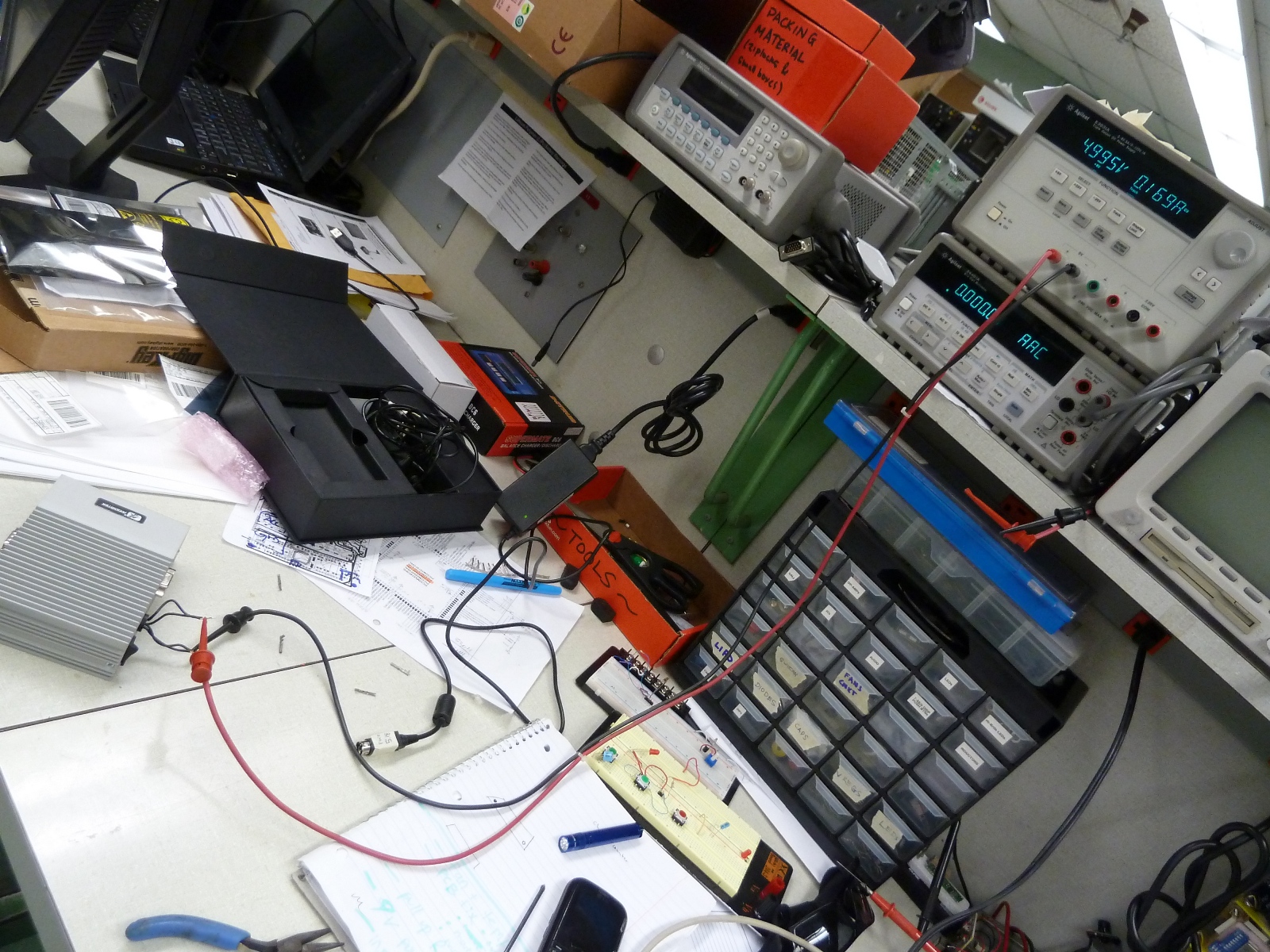
Marcelo found a novel way to measure the current draw of the Atom by powering it with the power supply shown in the image below. At startup, the maximum current draw achieved (and only momentarily) was about 1.6A, and the draw seemed to vary between 0.9A and 1.4A even with the Pico projector charging via USB. The setup is shown below.
WEEK 08 SUMMARY
Accomplishments: The completion of the charging circuit was the largest success this week. Time can now be spent on other areas of the design.
Weekly Work Total: 8.5 hours
Project Work Total: 110.5 hours
Week 09
October 17, 2011 (6 hours):
All components (GPS, Accelerometer, etc.) were moved to the solderboard, and power was directed to the breadboard from the solderboard in preparation for testing the fuel guage IC. The connections between the microcontroller and other devices were also put onto headers and labeled more clearly to facilitate easy plugging/unplugging of devices. The workspace was also cleaned.

October 18, 2011 (2 hours):
The fuel gauge circuit has been completed on the breadboard. The battery will be emulated by a DC power supply and the load by a simple resistor. I2C testing has yet to be completed.
The fuel gauge's connections make it hard to prototype cleanly on a breadboard.

October 19, 2011 (7 hours):
The thermometer circuit was tested on the breadboard by Marcelo. The PIC microcontroller was having many issues programming. The workspace was reorganized immensely to hopefully facilitate better workflow and prototyping for all. I2C was implemented on the microcontroller after studying how I2C works in-depth; however, testing the communication functions was not started. A circuit was devised by Aditya to enable the microcontroller to turn on/off the two fans; this was prototyped on the board and microcontroller successfully.

October 20, 2011 (7 hours):
The microcontroller was experiencing huge difficulties programming. The cause is unknown. The spread-out layout of the prototyping is the assumed cause. All unnecessary components were removed from their headers to eliminate possible sources of the cause; only the line-level driver, the microcontroller, and the fuel gauge remain. The I2C functions, after some modifications, communicate correctly. Ethan helped immensely by providing a USB signal analyzer for use in testing I2C. The voltage register was read from the microcontroller, and a trendline was made for converting the raw values returned by the fuel gauge into voltages. The testing setup and trendline data are shown below.
The power supply is providing 8.2V, the fully-charged voltage of the battery.
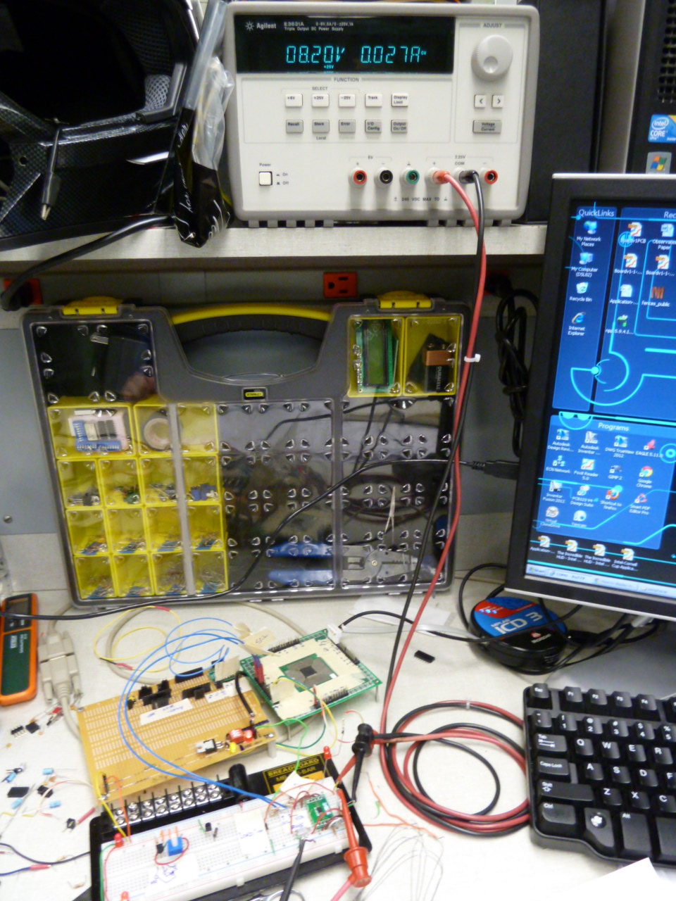
Notice the linear regression has an R-squared value of nearly 1, almost perfect.

WEEK 09 SUMMARY
Accomplishments: Successful communication with the fuel gauge IC was key this week. Now that communication has been established, time may be spent configuring the device.
Weekly Work Total: 22 hours
Project Work Total: 132.5 hours
Week 10
October 24, 2011 (4.5 hours):
The microcontroller has suddenly started printing a 'd' character in the place of '%d' in sprintf strings instead of the integer variable specifiec. This issue has been reported on the Microchip forums previously, and a new post was made on behalf of this project. The problem was fixed in our case by reverting to an old version of the code repository. There may be an issue with using sprintf inside functions. An ability to write application parameters to the EEPROM of the fuel gauge IC has been demonstrated. All that should now be left is to input the needed parameters to EEPROM.
October 25, 2011 (8.5 hours):
Worked on TSSP and presentation. Reprogrammed the microcontroller to send an integer from 0-9 periodically one each second for Aditya to test COM communication with a demo C# application being developed.
October 27, 2011 (7.5 hours):
Time was spent poring over documentation for the DS2782 Fuel Gauge IC to determine which appliction parameters needed to be programmed to get an accurate battery reading.
The DMM was used to measure the 5 mOhm sense resistor for one of the parameters; however, it does not appear to read such small values accurately even using the more accurate 4-wire measurement mode. The 5mOhm 5% resistor was reported between 9 mOhms and 1 mOhm, far out of tolerance. Because of this, it seems pertinent to order a more precise resistor to eliminate any potential source for significant error.
All necessary application parameters were programmed; however, accumulated current is measure in volt-hours instead of amp-hours. This proved difficult.
A Microchip official also posted on the forum mentioned previously that a hotfix will be available tomorrow (Oct 28) for the %d/%f bug.
October 28, 2011 (6 hours):
It was noticed that one of the parameters needed was actually based upon the current sustained through the battery just before the charge is finished. This value was calculated by measuring the resistance of a known, small resistor.
The CURRENT register of the fuel gauge IC was read, and it was noticed that the value was wildly incorrect. It was afterwards noticed that voltages varied by upto two milli-volts between some theoretically equal connections. As a result, the fuel gauge IC was moved to a solderboard shown below. The CURRENT register afterwards reported values precisely within the range expected.
The solderboard was cut in half and unfortunately cracked in two corners. This did not effect any soldered components thankfully.

It was next noticed that the TEMP (temperature) register was reporting wildly
incorrect
values. Open source Linux drivers (license: GPL) were found online for the DS278x series of fuel gauges. These drivers provided much insight into the temperature conversion. The voltage measurement (previously calculated based upon the regression) was also fixed to report values relative to the IC rather than the actual value. This error could have easily manifested as improper detection of charge or empty states if left un-fixed.
At the end of the day, temperature, current, remaining mAh of the battery, and initialized application parameters were all being reported correctly. The only parameter not being reported as expected is the percentage of battery left (RARC). This may be as a result of the relatively low current draw of the test setup (the IC may detect the standby state rather than the active state).
WEEK 10 SUMMARY
Accomplishments: The fuel gauge IC (DS2782) is working mostly correctly. There is sufficient work complete to consider the chip very nearly fully-prototyped; however, a small amount of work will have to go into selecting parameters for finished device operation as the prototype cannot completely emulate the device. Overall, this week has been a huge success.
Weekly Work Total: 26.5 hours
Project Work Total: 159 hours
Week 11
November 1, 2011 (3 hours):
The fuel gauge's RARC still reads improperly after attempting to change the parameters to match the prototype's current characteristics. The RARC formula was analyzed in the data sheet for clues; however, a clear solution could not be gleaned. It may be that the fuel gauge needs to execute a "learn cycle" of discharging the battery to empty and then charging it again to full.
November 2, 2011 (3.5 hours):
An Explorer 16 test program was made to send UART (RS232) packets of 1s and 0s. This was used to test the serial communication in C# through a multithreaded GUI.
Some time was spent soldering the first linear regulator and some bypass capacitors on the PCB.
Time was also spent debugging the C# multithreading which was not working. A good example of a serial communicating program that uses callbacks was found online to help, but the code was not tested. It remains for a later date.
November 3, 2011 (5.5 hours):
The battery charging IC was soldered and tested successfully. The Vsel pin originally designed to be pulled high was cut and soldered to ground to set the voltage regulation to 8.2V instead of 8.4V.
A USB-interfaced screen branded Mimo was found in a garbage heap and was given to the team by Chuck Barnett. This may be much easier to mount and keep weatherproof than the projector for our optics.
Time was spent trying to install Windows Imbedded 7 on the Atom motherboard; however, the compact flash card is seen as removable media which does not allow OS installs. Aditya will attempt to remedy this by formatting the flash from his home computer.
November 4, 2011 (2 hours):
The 5v and 3v regulators were soldered to the PCB; however, the 3v regulator does not output 3v but 4.5v. Aditya remedied this problem using a few resistors successfully.
November 5, 2011 (5 hours):
Time was spent creating the reliability and safety document for this week. The document was completed except for the summary.
WEEK 11 SUMMARY
Accomplishments: The battery charging IC and power supply regulators that power it have been soldered to the PCB and tested. The 5v and 3v regulators were also soldered to the PCB. A Mimo brand USB screen was found and tested with combiner glass to great effect.
Weekly Work Total: 19 hours
Project Work Total: 178 hours
Week 12
November 7, 2011 (1 hour):
Worked on TCSP presentation for Wednesday.
November 10, 2011 (5 hours):
The USB cord soldered to the Mimo display came loose. It was soldered back on and more care was taken to make it more rugged. The images below show the PCB-side of the newly-soldered display, and the next shows the screen working next to one of the monitors in lab.


There was a poorly-soldered pad of teh 3.3v regulator that was causing the output to read 4.4v; this was promptly and easily fixed. The biggest success of the day came with the successful programming of the microcontroller after breaking a few hair-sized solder bridges between pins.
November 11, 2011 (1 hour):
Aditya soldered the debug LEDs on the PCB, so time was taken to move all necessary files from the 'Prototype_Code' code directory to the 'Final_Code' directory. After this, the 'LEDs.h' file was modified to incorporate the new LED positions. The LEDs were tested successfully.
UART/RS232 communication was tested next. UART data is being sent by the PIC; however, the MAX3232 is not transmitting the data received. It may be necessary to consider that the new MAX3232 ordered may not have the same pinout as the old one.
WEEK 12 SUMMARY
Accomplishments: The TCSP was completed for this week quite early due to some other duties. The Mimo display was fixed. The microcontroller programs (a huge success) and the LEDs are properly programmed. The UART, however, is not working correctly.
Weekly Work Total: 7 hours
Project Work Total: 185 hours
Week 13
November 13, 2011 (4 hours):
Fixed MAX3232 issues by flywire. Tx and Rx from the micro to the 3232 were switched. It is confirmed that UART <-> RS232 works

November 14, 2011 (11.5 hours):
All components soldered to the PCB.
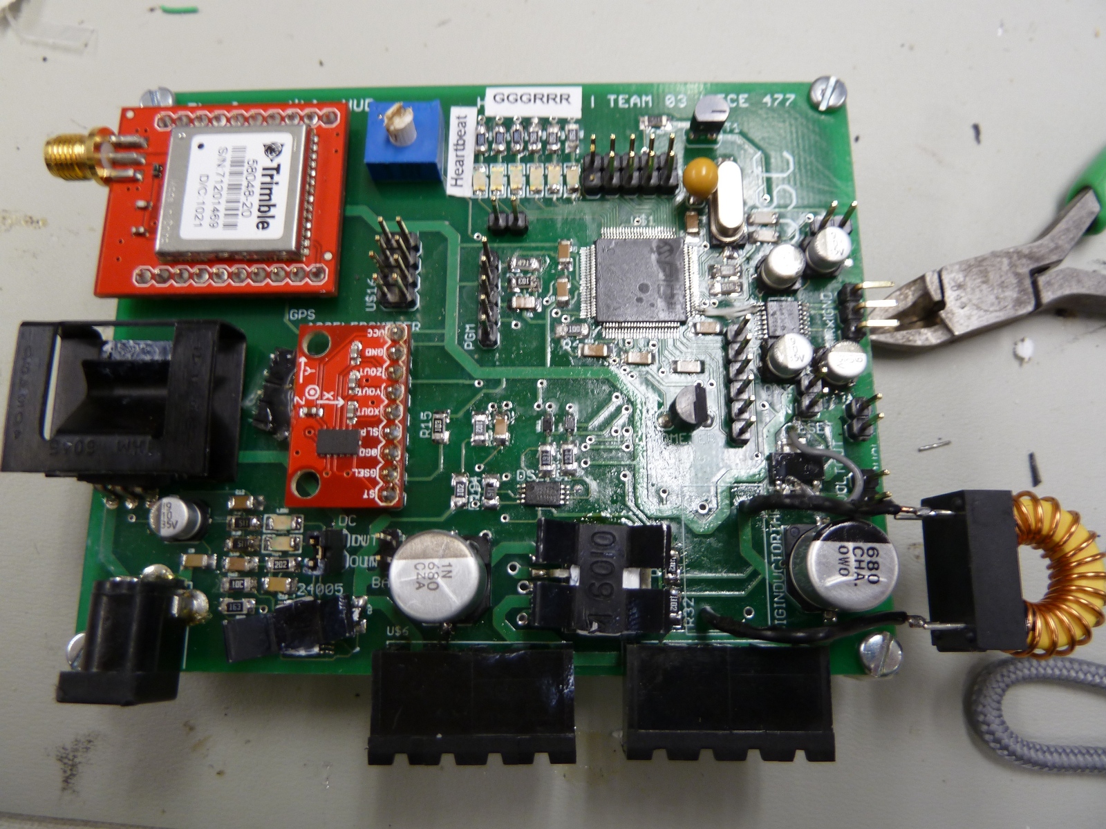
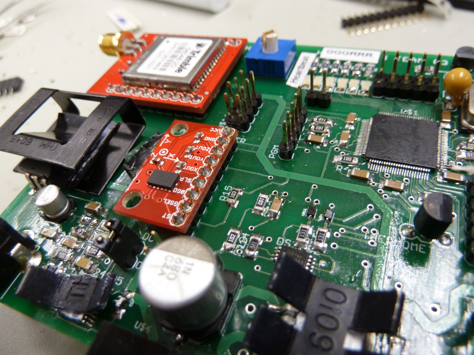
GPS + Fuel Gauge both work. Huge success! The MAX3232 is giving inconsistent output values. This was determined to be a result of the Rx and Gnd signals being shorted inside the cable.
After fixing the cable, the micro was getting only 250mV of power, a problem. It was determined that power and ground were shorted together. The following components were removed (in order) to determine the cause:
* Bypass Capacitors
* Max3232
* Accelerometer
* GPS
* Microcontroller
The microcontroller was determined to be the cause. Time was spent to replace the microcontroller and put all the other components back on the PCB. The device was demonstrated as working yet again.
November 15, 2011 (1 hour):
Time was spent examining the Copernicus GPS datasheet/manual for information about packet structure. It was determined that the GPS would best suit the purposes of this design when operated in TAIP communication mode (a proprietary communication mode developed by Trimble, the manufacturer). The command/response packet structure is relatively simple. Time was also spent briefly designing the overall method of collecting GPS data. It is suggested that various buffers be filled as packets are received that will be separated and translated into the proper item and value.
November 16, 2011 (2.5 hours):
The microcontroller code was updated to perform ADC conversions of accelerometer and thermometer data. These items are now dependent on the microcontroller timer module rather than the GPS UART interrupts as suggested during the programming design review.
November 17, 2011 (7.5 hours):
The GPS algorithm that decodes the GPS output and sends it to the Atom motherboard has been completed successfully.
November 18, 2011 (5 hours):
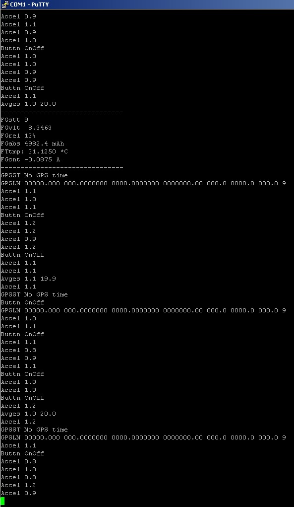
Pushbuttons have been programmed into the input header of the micro code. A GPS buffer bug was found and fixed. New fuel gauge IC settings were written to the IC reflecting the final design's hardware. At this point, all microcontroller code has been completed. The only task remaining is to clean up the fuel gauge's output. It is outputting extra information now for discharge testing. See an example of the output below and the battery discharge setup.
Battery discharge cycle testing began (see image below).

WEEK 13 SUMMARY
Accomplishments: The PCB is now completely populated and tested. All of the microcontroller output is now more or less finished also. Battery testing is the next step, as well as finishing the buttons.
Weekly Work Total: 31.5 hours
Project Work Total: 216.5 hours
Week 14
November 21, 2011 (2.5 hours):
Attended Cornell Cup webinar. Worked with Marcelo on the PIC-Atom communication packets. Started assembling final report.
November 22, 2011 (1 hour):
Cleaned up the fuel gauge IC's output and updated to version 0.9.0. Version 1.0.0 will be achieved with all buttons (easily extensible) being programmed. Battery drain testing was continued also. It drains slowly currently; testing the discharge with the Atom connected should be the next step.
WEEK 14 SUMMARY
Accomplishments: Microcontroller almost updated to version 1.0.0; only pushbuttons remain. The packet structure for micro-Atom communication has been defined.
Weekly Work Total: 3.5 hours
Project Work Total: 220 hours
Week 15
November 27, 2011 (7 hours):
Worked on Final Report document.
November 28, 2011 (2 hours):
Worked on Final Report document.
November 29, 2011 (2.5 hours):
Worked on Final Report document.
November 30, 2011 (4 hours):
Attended Cornell meeting. Worked on Final Report document.
December 1, 2011 (9 hours):
Tested GPS output of microcontroller successfully. The test rig used outside is shown below.

Tested Atom power (draws 350 mA while off, 1.9-2 A starting Windows, 2.4 A max). After testing the power draw, the Atom's power was sourced from the PCB successfully. The connections are shown below.
.JPG)
Set up AutoHotKey script to keep GUI on Atom running at all costs (will start at boot, restart after a crash, refocus if un-focused, and move to the correct position if moved).
Drained battery to empty.
WEEK 15 SUMMARY
Accomplishments: Final Report document is well on its way to completion. Keeping the GUI on the Atom alive at all costs was also implemented.
Weekly Work Total: 24.5 hours
Project Work Total: 244.5 hours
Week 16
December 4, 2011 (6.5 hours):
Worked on Final Report for 2 hours.
Implemented and tested micro code for pushbuttons (Now with a nice daughterboard with which to interface shown below).

Worked on Atom GUI to fix a file writing bug Marcelo was working on. The problem was a ':' in the file's name.
Worked with Brian Bowman to try fixing hanging/crashing problems to no avail. The likely culprit is serial communication. The exception given suggests that the port may be being cleaned up by the garbage collector while the program is still using it; this is a huge problem. It may be fixed by implementing a periodic check of the pointer.
December 5, 2011 (4.5 hours):
Button and thermometer connections were made to easily plug/unplug from PCB. 3 of the 5 PSSC's were demonstrated to George Toh for preliminary completion. A battery charging IC issue was encountered where the IC would stop charging after roughly one minute. The cause is unknown; luckily, the back-up plan of using an external charger was in place.
December 6, 2011 (7.5 hours):
The remaining 2 PSSC's were demo'ed to George Toh for preliminary credit. The unit was also tested outside around the MSEE building to great success. Some minor bugs were found including altitude display, but the device itself was performed very well.
December 7, 2011 (4 hours):
All five PSSC's were demonstrated to George Hadley for final credit. Data logging was also tested on a bicycle, but a time detection bug resulted in the logged data being lost. This bug was subsequently fixed.
Time was also spent working on the final report.
December 8, 2011 (7 hours):
A long test of the device was the order of the day. The unit was tested for a total of 1 hr 55 minutes until battery depletion, and data was logged from various city buses and a personal vehicle around the West Lafayette area. This test was a great success; 20+ minutes of video were taken and 90+ minutes of data were logged.
In preparation for the Cornell cup, methods of powering the new Atom boards were explored. Though the boards use 12V for power input, it appears it is quickly converted to 5V and essentially unused. It remains to be seen whether the unit can function fully with the 5V rail powered but the 12V rail left unconnected.
The 270/362 presentation was also prepared.


