Jacob Champion's Lab Notebook
Week 01
January 12, 2010 (1.5 hours):
Our team met after class this Tuesday to try to get a better idea of what game
we wanted to try to create. We're all excited about the idea of a networked,
telepresent game board, but we're not as excited about the details. We left without
a very good idea of what we wanted to do.
Sean, Kelli, and I met with Dr. Johnson afterwards to try to bounce some ideas
around and actually get somewhere. He was able to point us in a few directions
that sounded promising. We agreed to meet the next day to "start from scratch"
and actually get a concrete proposal out the door.
January 13, 2010 (2 hours):
Our team met once after class to try to hash out more ideas. Luckily, we appear to
have one good one -- we want to construct a wearable "gauntlet" that straps to a
snowboarder's or skier's arm and gives information such as location, speed,
and temperature through headphones.
After a short break, we met again to write our preliminary project proposal. George
has volunteered to be the team leader.
January 14, 2010 (1.5 hours):
We met as a team after class to get the lab code and set up our workstation.
We installed basic helpful programs on our team laptop and the workstation PC.
We also set up our team website; it currently is nothing but a placeholder. The
Python script to submit our finished project proposal is broken, so we get to wait.
WEEK 01 SUMMARY
Accomplishments: Came up with a project idea
and created a preliminary project proposal.
Weekly Work Total: 5 hours
Project Work Total: 5 hours
Week 02
January 20, 2010 (2 hours):
We all met for an hour before class to set up our TCSP presentation. We
created our PSSC's and came up with a more concrete project description --
our Gauntlet will navigate via GPS waypoints, provide downhill velocity
calculations with either an onboard accelerometer or altimeter, and
communicate with the user through headphones.
After class, we continued to talk about what we wanted the Gauntlet to
do, and we started work on Homework 2. I'll be in charge of getting
Homework 3 (that's the initial design constraints) out the door. I'll
also be in charge of the software design narrative.
January 21, 2010 (2 hours):
Today we met to finish up Homework 2 and also to start discussing the
interfaces we want to use with our chip. It looks like we'll be using
a lot of serial components, so we'll probably need to use some sort
of serial bus logic (maybe SPI?) to avoid tying up too many wires with
communication. We've tentatively decided to design our board to use
both an altimeter and accelerometer/gyrometer combo for the most
flexibility in terms of the information we present to the user. If
one or the other doesn't work out, we can simply leave it off the PCB
and write it out of software.
As far as initial responsibilities go, I'm in charge of the sensor
and user interfacing. Sean and I will be tackling the main CPU logic
together.
WEEK 02 SUMMARY
Accomplishments: Finalized project requirements
and began component research.
Weekly Work Total: 4 hours
Project Work Total: 9 hours
Week 03
January 25, 2010 (1 hour):
I did some individual research on components -- specifically, the
sensors our project will use. Our primary choices for altimeters are
chips which communicate via SPI and those which communicate over an
analog interface. Once that decision is made, the final decision comes
down to resolution (one chip is able to sense changes in pressure equal
to 9 cm of height, which is more than enough for our purposes).
Accelerometer/gyro combinations are much more expensive -- and much
more confusing. I am not entirely certain of the calculations necessary
to compute a chip's velocity down a hill, regardless of its orientation.
Some sort of tilt sensor will be necessary, but since most tilt sensors
assume that the object itself is stationary, this is going to be more
difficult than I assumed.
Finally, the GPS seems like an easier choice. The Parallax GPS systems
available online are cheap and can interface via an RS232/TTL serial
interface. The top of the line is still under $100, but it can sync
with a maximum 20 satellites and takes only 45 seconds on average to
get a link. As an added plus, it will operate in below-freezing
conditions, which is important for a skiing/snowboarding application.
January 28, 2010 (1 hour):
Kelli and I met with David after class to discuss our PSSC's. The
gyroscope problems have been alleviated to some extent -- it looks like
we will probably be removing the downhill velocity requirement in
favor of a rechargeable battery monitor. That way, we can use a
three-axis accelerometer to measure airtime for jumps and wipeout
situations. We'll use the altimeter data to help with velocity
calculations, and an added thermometer to give temperature information
to the skier.
Kelli found an MP3 decoder chip that can interface directly with an
audio jack. It looks like a really good solution, and it has several
operating modes and functions that would be very useful if we change
up our audio capabilities later.
January 31, 2010 (3 hours):
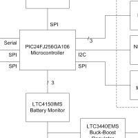
George, Sean, and I met to discuss the changes we've made to our PSSC's.
I spent a little bit of time drawing up a new block diagram, and we
each began research on different parts of the system. George is getting
the power and battery control, Sean is looking at the GPS and Flash
memory interface, Kelli is researching audio, and I am looking at altimeters
and accelerometers.
I did have a pretty good idea of which altimeter we wanted (the VTI SCP1000)
because of its onboard thermometer, easy SPI interface, and very fine
resolution (9cm ideal). However, it has 18 tiny below-chip pins which would
be a nightmare to solder. We could get a demo board, but that wastes a lot
of space. I'll likely need to continue looking at pressure sensors.
The accelerometer research I've done is similar -- either we get an easy-to-solder
surface mount part with terrible features, or we get a nice, fully-featured
chip that would be a nightmare to solder. This is slightly infuriating.
George thinks that we'll want an Atmel AVR for its floating-point
support. We'll finalize our micro after we choose the peripherals, which
is not an easy task...
WEEK 03 SUMMARY
Accomplishments: Finalized (again) our PSSC's. Got a
working block diagram and split up part research.
Weekly Work Total: 5 hours
Project Work Total: 14 hours
Week 04
February 1, 2010 (2 hours):
I did more research on accelerometers and pressure sensors after class. The
Freescale MPXA6115 seems to be a good, workable replacement for the VTI
pressure sensor we were looking at; it works in the pressure range we want and
provides an analog output that can be read using a 14-bit ADC for 55 cm resolution.
It does not have an onboard thermometer, though. The
Bosch BMP085 is a I2C solution which is cheaper, lower power by a factor of 300,
and higher resolution -- but it comes in a CLCC package which will be nearly impossible
to put on our board. We should see if they have breakout packages...
It looks like we won't have much of a choice in accelerometer packaging; almost every
single good three-axis solution I can find comes in an LGA package, which will be
a nightmare to solder.
I put some work into Homework 3; the rest of it will need to wait until we choose
our final peripherals.
February 2, 2010 (1.5 hours):
More research. The
Bosch BMA150 looks like it will be the best accelerometer choice.
It has a SPI interface, incredibly low power consumption, an onboard thermometer
to make up for the Freescale, and motion interrupt support. Unfortunately... it has
a 3x3 mm footprint and a 12-pin LGA. We'll see how good George's soldering really is!
EDIT: Scratch that; the
Analog ADXL345 has a breakout board from Sparkfun. It
is much more fully featured and will not have the soldering problems that the BMA150 would.
The SCP1000 has a breakout board available too. That will make it much easier to play with,
and the SCP1000 was our first choice anyway due to ease of use and power consumption.
February 3, 2010 (3.5 hours):
Much of yesterday evening and this morning were spent working on the TCSP presentation I
gave today. It went well; I explained the selection rationale for the MP3 decoder and the
three-axis accelerometer. After the presentation, we continued research on the components
in our design, especially the power controls and voltage regulators. We have selected a
2000 mAh Lithium-Polymer battery to power the circuit, so we will need some sort of buck-boost
DC converter to keep a 3.3V output at all times.
I spent an hour or so working on Homework 3 after the group meeting.
February 4, 2010 (6 hours):
All final component selections were made today. After a long meeting, we selected a PIC24
micro to use with our board -- it provides a good amount of peripherals and GPIO pins. We
also ordered our altimeter, battery, accelerometer, and audio decoder off of Sparkfun, so
we should be receiving them next week.
I spent a large amount of time on Homework 3 -- I wasn't quite sure how much detail was
desired in the component selection, but I kept the body of the report under 5 pages. I also
made the final block diagram for our circuit (below).
WEEK 04 SUMMARY
Accomplishments: Made final component choices and completed Homework 3.
Weekly Work Total: 13 hours
Project Work Total: 27 hours
Week 05
February 9, 2010 (1 hour):
The group met after class to work on the PCB layout. I printed off every datasheet
for the components so that we can use them easily. We also ordered more part samples; a good
portion of our components should be here by next week.
Notably, we found samples of the Ergo-Case
available online. This looks like a perfect match for our wearable device, especially since we
don't have the expertise to machine our own enclosure.
February 10, 2010 (1 hour):
After Sean's packaging presentation, we went back to the lab and continued putting together
the components and PCB in PADS. I'll start on the PADS tutorials tomorrow, because I am completely
lost in that program.
February 11, 2010 (3 hours):
I spent some time going over more PADS tutorials, and I think I have the design process down.
I created labels for the SCP1000 and the ADXL345. Sean was using basic headers for the two sensors,
but having a footprint of those sensors on the board will make things a lot easier in routing.
I also modified some of the existing part schematics, like our power components, to be a little bit more
intuitive.
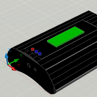
After class, Kelli and I tried to help Sean with the packaging CAD. We didn't get very far -- AutoCAD
2009 is a nightmare to deal if the last time you used AutoCAD was in high school. Luckily, George
was able to help after I left, and Sean has a very nice looking CAD drawing of the Ergo-Case (below).
February 13, 2010 (3 hours):
George got the Sparkfun sensors/battery and the Microchip components in yesterday, so we met today
to play with them while Kelli worked on the schematic. I soldered headers onto the ADXL345 after
George showed me his techniques with the SCP1000, so both boards are ready to be used for debugging.
I put together a hand-clocked board using our SCP1000, but it quickly became clear that implementing
the SPI protocol with pushbuttons (and expecting there to be no problems with circuit bounce) was
going to prove prohibitively difficult. George is coding up a SPI master for some of his PIC uCs,
and I will work with an MSP430 tomorrow to test out the functionality.
February 14, 2010 (3 hours):
I used an MSP430 today to check to see if the SCP1000 was working properly. Unfortunately, it took me
the better part of three hours to do. The part was giving me erratic results, and I was afraid that
I had accidentally fried it (I spent close to half an hour checking surface mount connectivity) until
I reread the datasheet and realized that I was overclocking the chip by a factor of ten. Lo and behold,
when I pulled the SCK frequency down to 1 MHz, the chip worked perfectly. By that time, it was quite late,
so I haven't yet been able to check the ADXL345.
WEEK 05 SUMMARY
Accomplishments: Learned PADS, chose our component housing, tested the SCP1000
part, and began work on the project schematic.
Weekly Work Total: 11 hours
Project Work Total: 38 hours
Week 06
February 15, 2010 (2 hours):
We met in the afternoon to keep working on the schematic. Kelli created a huge spreadsheet with
all of the microcontroller-interfaceable pins of each part listed, and we used it to assign
groups of pins on the microcontroller. Luckily, George has used PIC uCs before, so he was able
to help us quite a bit with his knowledge of what pins were reprogrammable, which pins
supported external interrupts, and so on. Kelli will use that list to connect pins on the
schematic for her presentation Wednesday.
February 17, 2010 (3.5 hours):
Met with the team after class to keep putting together parts of the schematic -- namely, the
Coulomb counter and the pushbutton interface. The PIC will not be able to source the current
needed for the LCD backlight, so we need a MOSFET switch circuit instead. There are several
discrete components which will be needed for the Coulomb counter in particular, so we used
the (luckily exhaustive) Linear equations to calculate the values of the (nearly ten)
external components for that circuit.
George received the GPS unit today, so I spent some time cutting apart a serial cable and
soldering it to a header so we can communicate with the GPS via serial terminal. I got basic
one-way communication working -- the unit sends position, velocity, and fix information --
but I haven't yet been able to communicate to the GPS to control it.
February 18, 2010 (3.5 hours):
More work on the schematic today -- the MOSFET switch circuit has been added, and we all
continued research on many differing parts of the circuit to be sure that our operating
modes make sense. George got a PIC programmer from Chuck, and he has some dev boards
for it, so maybe we can start software work soon.
I did some more basic work with our sensors to find operating and electrical characteristics.
I was able to successfully control the GPS output via TeraTerm, and it turns out that
the sirfStarIII chipset that the GPS module uses takes only half the current at 3.3V that
it does at 5V. This is great news for our battery life, since the GPS will need to be on
almost constantly to facilitate good waypoint tracking.
February 19, 2010 (0.5 hours):
I received the Linear components today (the Coulomb counter and the buck-boost regulator).
Next week we might be able to set up a basic power circuit to check their functionality.
February 21, 2010 (3 hours):
I made a huge Digi-Key order based on the parts we have yet to get for our circuit:
- a 5V DC wall wart
- surface-mount headphone jacks
- DC barrel jacks
- the Newhaven low-power character LCD
- N-channel enhancement MOSFETs for use as switches
- protective gaskets for the SCP-1000
- a high-quality inductor for the buck-boost regulator
Hopefully this should give us plenty of things to work with for the PCB layout. The
list doesn't include discrete components, but that should be easier than the research I
needed for this order.
WEEK 06 SUMMARY
Accomplishments: The team completed almost all of the schematic and tested
the GPS unit. We also ordered the remaining critical Digi-Key components.
Weekly Work Total: 12.5 hours
Project Work Total: 50.5 hours
Week 07
February 22, 2010 (3 hours):
Sean caught that I did not order a microSD card slot for our board. Cue a mad rush for
Digi-Key's sales department to alter my order before it shipped... luckily, I caught them
in time and it is on its way.
I spent a great deal of time creating PCB labels for the surface-mount components I
ordered. The DC barrel, audio jack, FET, and inductor are now library components that
we can easily push into our existing schematic/layout.
February 23, 2010 (1.5 hours):
We all met after class to discuss layout concerns. The autorouter appears to be terrible
at placing components in ways that make sense. George has a basic layout, so at least all
of our parts are on the board.
February 25, 2010 (4 hours):
We made a huge breakthrough in the PADS autorouter -- if components are placed carefully
in groups and combined into unions, the autorouter is able to make intelligent decisions
on where to place the wires. Kelli, Sean, and I spent a great deal of time placing
part groups like the buck-boost, the audio controller, and the fuel gauge. The PADS
route looked a lot cleaner after that, so we'll be able to hand-tweak more of the routes
ourselves and not have to worry about doing the whole thing by hand.
In other news, the Digi-Key parts are in today; I plan to play with them tomorrow.
February 26, 2010 (2 hours):
I took a look at the Digi-Key parts today -- everything appears to be in order. I played
around with some of the parts, but I'll wait until we meet this weekend to really get into
them.
After looking at the datasheets from some of our power controllers, I realized that we
have no undervoltage protection on our battery. Without it, the buck-boost will simply
continue to draw current; this could possibly cause the battery to bloat/explode. We will
need some sort of protection on the circuit for this.
February 28, 2010 (4 hours):
We met this evening to begin planning the design presentation. I spent some time reworking
parts of the PCB; a few of the routes are still very messy. We chose an analog comparator
to shut down the battery (the
ADCMP361), and since the course staff really want us to put a more accurate clock on
our board, we chose an 8MHz oscillator to use with the PIC24F.
Kelli and I tested out the new Digi-Key components and compared them to the PCB layout
footprints. We have a slight problem with the pad placement on the microSD layout, but
that should be easy to fix. The backlight on the character LCD looks great, and it's low
power as well.
WEEK 07 SUMMARY
Accomplishments: Our team finished the preliminary PCB and had great success
with the autoroute capabilities. We received and checked Digi-Key
parts, and we began planning our design review presentation.
Weekly Work Total: 14.5 hours
Project Work Total: 65 hours
Week 08
March 1, 2010 (3 hours):
NOTE TO GRADER: The following entries, up to March 11, are backdated; they were updated out
of my notes from the days involved after Spring Break.
The team met to continue to put together the design review presentation. We had previously
split the presentation into sections so that each person could take a specific part and
mark up slides for it -- my sections are the power circuitry and the component selection
rationale. I put together some basic outlines for what I want to say for those sections,
but the slides (and the presentation as a whole) are nowhere near complete.
March 2, 2010 (4 hours):
Today we really put together the presentation and polished it. I'm concerned that we haven't
done much work with the software at this point in the game -- the most we have done is tested
the sensors with another microcontroller (the MSP430 mentioned above). We will need a good
schedule to finish coding in a timely fashion. As for the presentation, we were able to add
a good amount of pictures to the slides to clarify the sections of circuitry we will be
discussing. I'm pleased with how the presentation is coming together.
We split up the schematic (which, until now, was a single wiring diagram on a D-size sheet,
with no off-page connections or busses) to 1) make it more readable in general and 2) allow
the circuit sections to be printed on B-size paper. The result is impressive -- it is now
much easier to find sections of our circuit and change them.
March 3, 2010 (3 hours):
Today was the presentation. We met beforehand to make last-minute corrections and print out
the materials required. I think the presentation itself went well; there were no show-stoppers
in our design except for a missing power/ground chip connection, and other than basic comments
on trace width matching, I believe we have a relatively workable design. One thing that will
need to change is the PCB chip placement; right now, there are too many crossed wires in our
layout, and I'd much rather we have nice traces to work with during debugging.
March 4, 2010 (3 hours):
I resolved to start looking at software now that we have a little bit of downtime until
the next deadline. I looked at MPLab (the Microchip IDE that we'll be using with our PIC24F)
and I asked Chuck for a development board so we can do some software work without needing
our board. Unfortunately, I wasn't able to do as much software work as I wanted to, so I'll
need to do some PIC tutorials this weekend.
March 5, 2010 (1.5 hours):
I spent a very small amount of time looking at the oscillator circuit. I don't think what
we have currently is correct -- having never done work with an oscillator crystal, though,
I can't really be sure of anything. In my research, I found the following picture from
Microchip:
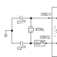
I don't know what to think of the series resistor, but it may be that we'll need to put
together the circuit, see if it meets our standards, and then tune the capacitors and
resistors as needed until the clock works properly.
March 7, 2010 (4 hours):
Today I really got into some software. I was able to do some PIC tutorials using MPLab,
successfully download test programs to the PIC dev board, and blink lights as a Hello
World program.
It occurs to me that, since the PIC24F we are using is slightly different from the one
on the development board, we will not be able to code for the one and expect it to work
on the other. Instead, we can use the MPLab IDE's software simulator for our production
code (at least until we get a working micro on the board) and use the development board
for basic proof-of-concept.
WEEK 08 SUMMARY
Accomplishments: Our team successfully presented our design review; with a few
modifications, it looks like we will be ready for the PCB submission next week. I did
software work using MPLab and was able to successfully communicate with a development
board. The oscillator circuit was added to our board, but it needs fine-tuning.
Weekly Work Total: 18.5 hours
Project Work Total: 83.5 hours
Week 09
March 8, 2010 (4 hours):
Today we began fixing our PCB layout problems, and we made small revisions to our schematic as we
did so. The power/ground issue for our charge counter is fixed. Unfortunately, today was a lot of
staring at our PCB and thinking of ways to make it better; very little in the way of improvements
was done.
March 9, 2010 (7 hours):
In contrast to yesterday, today was a lot of work. We began to tear up whole sections of traces
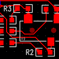
from our PCB and reroute them in a more favorable manner; the power circuitry especially has an
entirely new placement on the board in order to isolate it from the rest of the data circuitry.
Kelli found an application note for our audio hardware that showed the best placement of components.
As it turns out, our existing circuit placement had nothing at all to do with the recommended layout,
so we revamped it entirely.
We were all ready to be done for the day after seven hours of hard work, but the audio circuitry
at the very least looks better than before.
March 10, 2010 (4 hours):
Again, today was a lot of PCB work. George is unfortunately gone until Friday, so we're down our
main PCB layout engineer. Kelli, Sean, and I put a great deal of effort into finding new uC pin mappings
that made sense given our circuit layout. We finally ended up moving the sensor circuitry to another
corner of the board, and it made an incredible difference in the cleanliness of the routing. At long
last, it is easy to see what circuits belong to which chip.
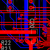
March 11, 2010 (6 hours):
As today was my last day of PCB work (tomorrow I leave in the morning for Austin), we put in one last
marathon push to complete the PCB layout. I spent a great deal of time learning the nuances of the PADS
copper pour capabilites, and so we have a good ground plane around our board. The power rail is a
line extending directly from our filter capacitor instead of a spiderweb of 3.3V signals, which should
have the additional effect of making our power much cleaner. Decoupling capacitors have been placed
in very favorable locations for our board as well. After looking at our final PCB layout, I am very happy
that we put in the additional time and effort to clean up the board.
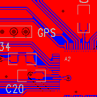
We completed most of our submission check-off today; we just need a few parts (most significantly, the
oscillator crystal) to be able to submit the PCB layout to Chuck.
WEEK 09 SUMMARY
Accomplishments: Our team completed the PCB layout for our board. Signals and
routing are significantly cleaner now, which should make debugging much, much easier.
Weekly Work Total: 21 hours
Project Work Total: 104.5 hours
Week 10
March 20, 2010 (1 hour):
I spent a small amount of time over Spring Break writing out flowcharts for how our software
should behave. Since most of this is timer-based, I think the main effort in coding will be
the calulation routines (velocity, whether or not to save a GPS waypoint, etc.), not the periodic
updates from the sensors on the board.
WEEK 10 SUMMARY
Accomplishments: I did some basic work on our software flowchart. Major
software work will need to be completed in the next week.
Weekly Work Total: 1 hour
Project Work Total: 105.5 hours
Week 11
March 22, 2010 (1 hour):
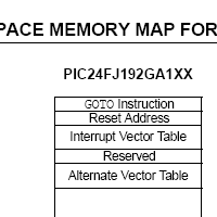
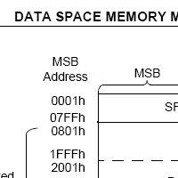
I did basic work on the Software Design Narrative. The memory maps for the
PIC24F are easy to read, which makes the research for that portion of the assignment
much easier. The interesting thing about the PIC is that it uses a Harvard architecture --
data and program memory are separate, and they use separate busses as well.
March 23, 2010 (6 hours):
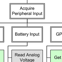
I have been putting a great deal of work into the Software Design Narrative. Today I created
hierarchy diagram for our software and put together the TCSP presentation. Although multiple
decisions have been made about the software design, I am still nervous about the amount of code
that has actually been written. The vast majority of our software exists as pseudocode.
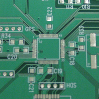
We got our PCB today. We did a visual inspection, and the board looks very good. We will
need to do connectivity checks on traces before pushing chips on the board. We found that
three passive component values had not yet been ordered -- we ordered them on Digi-Key, and they
are already on their way.
March 24, 2010 (4 hours):
Unfortunately, Kelli has discovered the first flaw in our circuit. As referenced by
this forum, the VS1011e
datasheet is misleading in its statements of an "internal
oscillator." We need an external crystal circuit to guide the MP3 decoder, which means we will
likely need to flywire from the microcontroller crystal, or construct a flywired circuit from
scratch and glue it to the board.
March 25, 2010 (5 hours):
Amazingly, the Digi-Key parts have already arrived. George soldered the buck-boost circuitry
to the board, and we tested the 3.3 volt output. Under no load, the circuitry worked well,
but the output fluctuated wildly with a 300mA load under boost conditions. Since the circuitry
is supposed to source up to 600mA load in these conditions, we troubleshooted for some time
before discovering grounding problems in our test circuit. In summary, the power circuitry
appears to be working properly.
The rest of the evening was spent working on the software design narrative. Sean has done research
into FAT16 file systems for the microSD card, and it turns out that Microchip has a
FAT16 library almost ready
for use. The development time saved will be well worth the memory and time overhead of the library.
March 26, 2010 (6 hours):
With about three hours of work, I finished the Software Design Narrative. Most work here was
on the PIC peripheral initializations, which to this point we had not paid much attention to.
My research in this area also uncovered some nuances regarding the order of register
initializations, so I'm glad I put in the work.
In the afternoon, I joined up with the team after they had completed the power circuitry on
the PCB. Initially, it appeared as if the circuitry was operating normally. However, upon
furthder testing, Sean and I discovered that the analog comparator fails to shut down the
circuit on an undervoltage condition. We hypothesize that the noise induced by the boost
circuitry is enough to interact with the analog comparator's hysteresis, so we may need to
add more filtering capacitors to the circuit.
March 27, 2010 (1 hour):
Sean and I met to finally get some actual coding done. We tested the UART in the simulator,
and tomorrow we will try to get the SPI driver working properly. The UART's NMEA decoder will
be another target for us in the immediate future.
March 28, 2010 (5 hours):
Sean and I met again to continue work on the UART. We have a working circular buffer system
and a basic API. We spent the remainder of our meeting working on a fixed-point format that
would allow us to store the numbers transferred by the GPS efficiently without a loss of
precision, and decided on a Q6.10 format -- six bits integral, ten bits fractional. This
gives us a range of [0, 64) and a precision of 2^-10, which is enough to store the needed
latitudinal/longitudinal minute data to an accuracy of approximately 2 meters. After creating
the format, we completed an ASCII-to-fixed-point conversion algorithm.
WEEK 11 SUMMARY
Accomplishments: Our team received the PCB from Chuck and completed/tested the
power circuitry. We discovered the first problem in our layout. I completed the Software
Design Narrative, and Sean and I finally began solid (non-test) work on the software.
Weekly Work Total: 28 hours
Project Work Total: 133.5 hours
Week 12
March 30, 2010 (4 hours):
After class, we continued working on the power systems. After a concerted effort to quell
the noise created by the boost converter, we finally decided to wait and see whether or
not it actually causes a problem. To be fair, the noise appears when we are pulling a
substantial load from the power rails (200 mA, which is supposed to be our maximum draw).
If the shutdown refuses to operate correctly, we may be able to push a low-pass filter
on the analog input to the comparator; capacitors alone do not appear to do anything to
help.
March 31, 2010 (6 hours):
After George's TCSP presentation, the team went to the lab to continue software and hardware
work. Sean and I worked on the battery monitoring software. The charge counter sends out an
interrupt every time a fixed quantity of charge passes in or out of the battery. A polarity
pin signals whether the current is into or out of the battery. The ISR for the charge counter
simply needs to read the polarity pin and either increment or decrement a counter. If the
counter gets sufficiently low, the Gauntlet will alert the user to the battery status and
begin to shut down nonessential circuitry.
We continue to have intermittent problems with the power circuitry. I believe the problem
is due to momentary shorts from "threads" of solder that I've noticed on the PCB. After
cleaning off the PCB with flux remover, the problems have seemingly disappeared.
George put the PIC24F on the PCB today, but it unfortunately did not operate correctly
right off the bat. Upon some hurried research, I found that an important voltage regulator
pin was left floating on our schematic. George performed our first flywire to the floating
pin, and the ICD2 programmer was able to successfully connect to, program, and debug the PIC
in-circuit.
I soldered the LCD circuit (consisting of capacitors and pull-up resistors for the I2C
interface) to the PCB, and the backlight switch works beautifully. (I have not yet been
able to test the LCD itself because I improperly crimped the connector to the LCD's
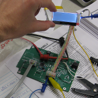
ribbon cable. That will be a job for tomorrow.) The picture below shows our PCB with
the microcontroller, ICD2 unit, and LCD operating under in-circuit debugging.
April 1, 2010 (4 hours):
Today Sean and I spent more time dealing with and debugging the I2C interface to the character
LCD. We found some initialization problems, but upon measuring the output with an oscilloscope,
everything seemed to be in order. We believed at first that the LCD was not initialized correctly,
and then George found that some solder connections were loose, but after debugging for some time,
we finally discovered that I had hooked the LCD up to our circuit board backwards. I doubt the
LCD has survived my mistake, but we will find that out for certain when we continue tomorrow.
April 2, 2010 (2 hours):
Sean and I spent some more time attempting to work out whether or not the character LCD was
destroyed when I hooked it up backwards yesterday. Unfortunately, the answer appears to be
"yes." The LCD's internal voltage converter does not appear to operate when turned on, and
the I2C interface does not provide an ACK bit during any communication. In the evening, I
ordered two new LCDs from Newhaven: one as an exact replacement, and one new LCD I found
which has a little bit more character space, uses exactly 3.3 volts instead of 3, and
has mounting holes for easy installation in our housing. We'll see which one meets our needs
better when we get them.
April 4, 2010 (3 hours):
I coded two main functions for the Gauntlet: the distance calculator and the number-to-speech
converter. The distance calculator utilizes several simplifying assumptions to make calculations
easier. The first is that the earth is flat -- this lets us compare distances by simply squaring
the components of the distance and adding them together, instead of having to use expensive
trigonometric functions. This should be accurate enough to a range of a few miles. The second
assumption is that the user will not cross either the Prime Meridian or the Equator during use.
This keeps us from having to use an extra variable for east/west and north/south storage for
latitude and longitude; instead, we will simply subtract the two measures and store the difference.
The number-to-speech converter is a bit more straightforward. A 16-bit number is parsed for
base ten digits using division. These digits are put into groups of three. Each group of three
is then broken into a hundreds group, a tens group, and a ones group. Sound files are queued and
output for each part, followed by appropriate suffixes ("thousand" or "hundred," for example).
To save the space which would otherwise be used for looking up the filenames for each numbered
sound byte, the files will simply be named numerically (e.g. "10" instead of "ten.mp3" for the
sound "ten").
WEEK 12 SUMMARY
Accomplishments: We finished the power circuitry, attached our microcontroller,
and successfully loaded and debugged programs in-circuit. Sean and I made headway into
the code base for our sensor interfaces and calculations, and we have completed much
of the Gauntlet's software.
Weekly Work Total: 19 hours
Project Work Total: 152.5 hours
Week 13
April 5, 2010 (2 hours):
I spent more time stepping through the distance and number-to-speech code I had written earlier
and caught a few bugs. I also stopped by the lab on my own time to write and test some utility
functions for the Gauntlet, such as integer-to-string converters.
April 6, 2010 (6 hours):
George received the mountable, larger LCD in the mail, so he attached a ribbon cable to it and we
immediately began to test it. Unfortunately, for several minutes it appeared as if we had created
yet another dud device, as the LCD would not ACKnowledge our commands over the I2C interface. Upon
looking at the datasheet, we discovered that the I2C address for the new LCD was different from
the old, and sure enough, we began receiving ACKs from our LCD for the first time this semester once
we made the change.
Unfortunately, we still did not see any activity on the LCD face itself. After finding sample code
for the LCD initialization in the datasheet, which included an inexplicable and undocumented series
of command bytes to be sent, the LCD finally began displaying characters which were sent to it.
After breaking from the group, I set to work on the SCP1000 altimeter interface, which operates over SPI.
The altimeter operates as follows: First, an initialization sequence occurs on powerup. The results
of the self-test run by the SCP1000 during this initialization are checked by reading device registers over
the SPI interface; if they match the expected values, the altimeter is operational. The pressure and
temperature measurements are triggered by an I/O pulse on the altimeter's TRIG pin, and it asserts its data-ready
pin upon a successful conversion. At this point, the PIC can read the temperature and pressure data
from the SCP1000 and perform the necessary fixed-point conversions to present the data to the user.
April 7, 2010 (9 hours):
George was able to solder the altimeter, the accelerometer, and the microSD holder to the PCB today,
so I set to work to see if the altimeter code I had written was at all correct. While I was doing this,
the team began testing the charge counter circuit. Unfortunately, the charge counter did absolutely
nothing during operation. We found that 330kohm resistors were used in place of 33kohm by accident,
which reduced the active-low SHDN and CLR pins on the device below their operating threshold, but
unfortunately, fixing these issues did nothing to help the circuit's functionality. To make matters
worse, the circuit's voltage divider that feeds the CLR pin has far too much of a voltage drop across
the first series resistor, suggesting that there is a short through or around the CLR pin. After plenty
of frustrating work, we decided to try again tomorrow.
I had my own frustrating debugging session with the altimeter after the rest of the team had left.
Although my SPI initializations matched those given in the sample code for the PIC24F, the SPI
interface refused to clock out data to the altimeter. I found several tangential bugs in the code
during this time, but none of them affected the operation of the SPI circuit. Finally, during one
last defeated look through the datasheet for the specific PIC24F used by our PCB, I discovered
that the pin mapping code connecting the SPI interface to the outside world was slightly different
than that used by other PIC24F devices. I will make this change tomorrow -- I am sure that it is
the culprit.
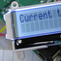
All was not lost for the day, however. Below is a picture of the LCD working with the integer-to-ASCII
function I wrote. I found that, in order to clear the LCD properly, a short delay is required after
sending the clear command and before sending any more characters. The picture shows a "current temp"
of 511 degrees Centigrade: our temperature is stored in a Q9.7 fixed-point format, which saturates
at a maximum value of approximately 511.992. This indicates that altimeter communication is nonfunctional.
April 8, 2010 (5 hours):
After changing the reprogrammable pins for the SPI interface to the correct numbers for our PIC24F
version, the PIC was indeed able to communicate with the altimeter. I was surprised by how easily
everything fell into place in terms of software after these pin mappings were fixed; the altimeter
responded perfectly to its initialization and self-test code and immediately set to work finding
us the current temperature. Once a second, the PIC triggered another temperature reading, and the
altimeter faithfully transferred results between 24.5 and 24.6 degrees Centigrade (about 76 degrees
Fahrenheit) back to the PIC to be displayed on the LCD. I am very happy to see this process work so
well, especially in light of the hours I put into debugging the interface yesterday.
Unfortunately, not everything went as well for us today as the SPI interface. While Sean and Kelli
worked on the safety analysis for the Gauntlet, I desoldered every part of the charge counter as
carefully as possible. I discovered no shorts on the underside of the IC, but unfortunately, removing
the chip solved both the voltage divider problems and a strange problem we have been experiencing where
the circuit is powered at 1.5 volts even though the power switch is off(!). Soldering the IC back on
brought back both problems.
After poring over the datasheet, we finally discovered a flaw in our schematic: the charge counter
is to be powered off of the battery voltage, not the 3.3V rail. Because the charge counter
works on mainly analog circuitry, it is possible that this voltage discrepancy between pins caused
the CLR pin to float and draw our voltage divider out of tolerance. George cut the power trace and
flywired the power to the battery voltage instead, but it appears that fixing this obvious mistake
has not still solved the problem. I believe that the circuit problem may have shorted the CLR pin permanently,
and unfortunately, we have already burned through both of our sample parts. George will call
Linear tech support tomorrow to see if there is anything we have missed.
April 9, 2010 (4 hours):
Today the charge counter was taken completely off of the PCB. Incredibly, it appears that removing the
charge counter has also fixed our voltage comparator problems. (Previously, the analog comparator -- which
is designed to shut down our circuit in a battery undervoltage condition -- was not triggering due to
noise.) Removing the faulty charge counter circuit, which is close in proximity to the comparator, has
caused the comparator to begin working properly. It shuts down at almost exactly 2.75V (the lowest voltage
our battery can take without undervolting).
Work continues on all sensor interfaces -- the microSD card and GPS in particular. Sean will work on
the accelerometer and microSD tomorrow in lab; I'll try to help him out when I return on Sunday.
April 11, 2010 (6 hours):
Sean had significant trouble interfacing with the microSD card yesterday, so I tried my hand at
debugging the circuit. Upon looking at the oscilloscope output, it became clear that although the
microSD card was responding to the stimulus from the microcontroller, the output was completely
unexpected and garbled. The solution to the problem presented itself when we found that single-stepping
through the code in the debugger allowed the card to correctly initialize; we added significant timing
delays in parts of the initialization code to allow the card to initialize correctly.
Another problem was solved when we switched from the Windows FAT16 formatting on the microSD to
the Microchip FAT16 formatting. We encountered serious problems in the Microchip library that kept
the PIC from finding files on the card when it was formatted with Windows FAT16. Upon switching
to the Microchip version of the formatting (and fixing a serious bug in the Microchip library that
kept 2 GiB cards from being formatted correctly), the PIC was finally able to read a text file
from the card and display it on the LCD.
Later, I wrote another text utility that takes a binary fraction and converts it to decimal text.
This will come in handy with our temperature display.
WEEK 13 SUMMARY
Accomplishments: We successfully interfaced with the LCD, microSD card, and altimeter,
bringing our PSSC completion to two out of five. In addition, we found that our charge
counter circuitry is faulty, and we are putting effort into solving the problem as
quickly as possible.
Weekly Work Total: 32 hours
Project Work Total: 184.5 hours
Week 14
April 12, 2010 (5 hours):
George ordered two 12 MHz oscillators so the audio circuitry -- which requires an external crystal
that we did not previously have -- could be tested. The original plan was to upgrade the PIC crystal
to 12 MHz, then run both the microcontroller and the MP3 decoder off of the single crystal. George
put the crystal and the audio circuit on the board, and we tuned the oscillator circuit with a
series resistor to limit the crystal drive (a little bit more than 2 kOhm limited the clock to a
3.3 volt swing). Just as we were about to flywire the crystal output to the audio circuit, however,
a prolonged read of the MP3 decoder's datasheet showed that the attached crystal would be grounded
when the MP3 decoder was reset. Since we may need to reset the decoder in use, and we cannot afford
to lose the PIC clock signal when we do this, a separate flywired clock will be needed for the decoder.
After working on the crystal hardware, Sean and I attempted to interface the GPS with the rest of the
circuit. We immediately found some bugs in our GPS receiver buffer code -- for one, the buffer did not
correctly reset during a buffer overrun condition. However, although the GPS transmits initial setup
information to the PIC correctly, it does not respond to queries from the microcontroller. Also, while
attempting to debug this problem, we appear to have temporarily shorted power and ground together
by mistake at the GPS header. Our buck-boost circuitry is more flaky now as a result, and a much higher
transient current is needed during powerup, but no parts were destroyed in the process. We'll need to
monitor the power circuitry closely for the next few days.
April 13, 2010 (5 hours):
Today I completed one of the most creative soldering jobs I have ever performed.
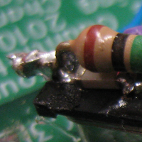
The above is a picture of the new 12 MHz oscillator attached to the MP3 decoder. I spent a good
amount of time putting the oscillator, its capacitors, and a parallel feedback resistor in place.
Chuck flywired the circuit to the decoder, and (incredibly) the clock began oscillating at 12 MHz
the very first time the decoder was enabled. Initialization of the VS1011e decoder requires enabling
streaming audio and setting the external clock frequency, among other more trivial settings. Luckily,
the VS1011e comes with builtin sine wave audio tests. After some coaxing, we were finally rewarded with
a thoroughly annoying 5 kHz tone.

We discovered that the reason the GPS was not responding to our requests for data was that the NMEA
messages we were sending were not correctly formatted -- they require a CR/LF terminator to be valid.
After sending the correctly formatted messages, the GPS responded perfectly to data queries. The next
step will be to take the circuit outside to actually test the GPS functionality.
April 14, 2010 (1.5 hours):
The audio circuitry passed its second test today, as we were able to successfully send an MP3 file
directly to the VS1011e and hear the output on headphones. I am astonished that the audio works as well
as it does, given the extent of our flywiring and the fact that we are only using a single 512-byte
buffer to stream MP3 data. Our fast (1 MHz) SPI clock rate seems to be serving us well in this regard.
This marks another completed PSSC for us (the first two being the use of persistent storage and the
monitoring and charge of an onboard battery pack).
April 15, 2010 (2.5 hours):
Today was yet another day of truly meaningful accomplishments. Sean and George spent time yesterday
night recording sound samples, and after a few bug fixes to my number-to-speech algorithm, Sean's voice
was narrating series after series of numbers through the headphones.
Ever since switching the clock on the microcontroller to 12 MHz from its internal FRC oscillator,
we have been having transient errors when communicating with the serial LCD -- missed characters,
incomplete screen clear operations, and failures to power on. At first, I was sure that this was due
to shorter intervals between commands, but the problems persisted even after introducing software delays.
After looking at the communication waveforms and comparing them to the LCD datasheet, Sean and I
discovered that although the LCD technically allows I2C communication of up to 400 kHz, it requires
a minimum low clock period of 1.3 us. Since the PIC24F cannot vary the duty cycle of its I2C clock, this
means that the maximum theoretical clock rate we can use is 384 kHz. After pulling the clock rate down
to less than 350 kHz to allow for stray capacitance and nonideal clock behavior, the failures we
had been observing with some regularity disappeared completely.
Pushbutton support (and necessarily, timer support) were added to the PIC today. Previously, our main
loop executed an inefficient software delay to implement timing functions; now the software architecture
is an interrupt-driven main loop that puts the processor to sleep if nothing is going on. This allows us
to save some power -- though in comparison to the power draw of the LCD and the GPS, the savings are
mostly trivial. The PIC24F has proven to be a very efficient device, even when running at full tilt.
All of these tests led up to the most exciting demonstrative test we have performed to date. We attached
the GPS, LCD, and battery pack to the board and took it outside to the open air. After approximately
one minute, the GPS indicated that it had received a full satellite lock, and it began to respond to
requests for data from the microcontroller, which displayed that data on the LCD.
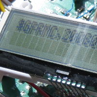
The above photo shows part of one of the NMEA strings received from the GPS: $GPRMC,200808.000,A.
This string indicates the sender of the message ("GP," or GPS), the type of the information given ("RMC," or
recommended minimum data), the current time (20:08:08.000 GMT, or 4:08 PM EDT), and the current status of
the GPS ("A," which indicates an active satellite lock). Other fields transmitted in this message include
the geographic position of the user, the current speed and heading, and the date.
April 16, 2010 (3.5 hours):
The group met today to semi-permanently mount the PCB to our housing.
George, Sean, and Kelli made a trip to Ace Hardware to find screws and
spacers for the PCB. The PCB fits snugly in our housing, and the
battery fits nicely beneath it.
We also continued testing the GPS. Although we had trouble at first
due to the rain, it eventually let up and we took it outside to test
Sean's NMEA parser. The parser worked without a hitch -- we were able to get
longitude, latitude, heading, and ground speed without any problem.
The GPS stopped sending us accurate information after a while, though,
so there are still bugs to be worked out.
April 18, 2010 (8 hours):
I came into the lab to continue work on the Gauntlet's code. In particular,
I focused on the pressure-to-altitude conversion, calculation of distance
based on latitude and longitude, and user-initiated waypoint storage.
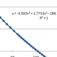
The above figure shows a graph of altitude (in meters) versus pressure (in kPa).
(This data is found on The Engineering ToolBox website.)
The curve fitted to this data is a cubic regression line that gives us no more
than two meters error from the actual altitude; this is more than good enough
for our purposes. The altimeter gives us absolute air pressure in Pascals, so conversion
to altitude involves converting the pressure measurement to a double, then plugging
that value into the regression equation and converting the result back to a fixed-point
number. Because of the floating-point operations involved, this is a microprocessor-intensive
operation, but it is only performed once a second, and the value gained in converting
the process to fixed point is not worth the effort, in my opinion. I am incredibly pleased
with the precision of the altimeter; I can lift the Gauntlet about a meter higher than
before and watch as the altitude reading changes by a meter. Noise is fairly low (about
half a meter maximum).
To determine the distance between waypoints, the Gauntlet assumes that the earth is flat.
We find the east-west distance and the north-south distance, then use the Pythagorean
Theorem to find the distance between the two points. (This is not incredibly accurate at
long distances, since the earth is not, in fact, flat.) Finding the north-south distance
is easy: compute the difference in latitude, convert to radians, and multply by the radius
of the earth. East-west distance is not as easy, because the distance associated with a
one-degree change in longitude depends on the current latitude. This computation involves
trigonometry (cosine, to be precise), so it has the potential to be an expensive operation
as well. In order to ease development effort, I again coded this operation using floating-point
math, but this is certainly not the most effective use of the microprocessor's time (it takes
approximately 4000 cycles to complete). If I have time to go back and convert the trigonometric
functions to lookup functions, I will.
Finally, I took the Gauntlet outside to test the altitude conversion, the distance calculation,
and the waypoint saving function. The altimeter works great, distance appears to be working
properly, and waypoints were correcly saved, but the GPS still stops sending new data
after a period of several seconds. We will need to continue to work at this new problem.
WEEK 14 SUMMARY
Accomplishments: The Gauntlet's audio circuitry is working correctly,
and the Gauntlet is able to "speak" to the user. Altimeter integration is
complete. We are able to interface fully with the GPS, and we are making
good progress towards navigating with the Gauntlet.
Weekly Work Total: 25.5 hours
Project Work Total: 210 hours
Week 15
April 19, 2010 (5 hours):
I continued working on the longitude distance calculation, as I'm not entirely impressed
with my first attempt at the problem. For one thing, my solution finds the distance along
lines of longitude instead of along a great circle on the globe, so it becomes very
inaccurate very quickly. I'll need more lookup tables to deal with this, but I think it is
doable. Unfortunately, this can't be my top priority -- our charge counter is still not
working, and we have spent weeks trying to find out why.
George did quite a bit of machining on the PCB and casing today to allow us to assemble the
final product more easily. Unfortunately, the machining of the PCB seems to have caused
unpredictable shorts on the board. Kelli and I spent a good deal of time trying to find
the offending pieces of copper, but the problem appeared to go away on its own after
hassle and frustration. George took the board back to clean and examine it, and it appears
to be working properly. We'll need to be very careful with the board during machining to
avoid this problem in the future.
April 20, 2010 (8 hours):
Sean and I created the waypoint stack algorithm today. This algorithm works in the following
way: First, the user specifies a safe point to navigate to in the event he/she is lost. Once
the Gauntlet sees that it is 25 meters or more away from that initial point, it pushes
the current waypoint location onto the waypoint stack, which is stored in a persistent
file on the microSD card. This continues until the user initiates "Emergency Mode," where
the microcontroller stops saving waypoints and begins to direct the user back to the top
of the waypoint stack. When the user is within 10 m of the waypoint on the top of the
stack, it is popped and the user is directed to the next waypoint. This continues until
he/she reaches the safe point on the bottom of the stack.
Later that evening, it was finally time to get the charge counter working. We have one
counter attached to a protoboard, and testing of that chip appeared to go well (an issue
arose where the counter did not appear to correctly indicate the polarity of the charge
passing through its sense resistor, but this was linked to a faulty oscilloscope probe).
Finally, after exhaustive checks of the PCB layout, and more connectivity and resistive
checks to determine that the PCB circuit was indeed the same as the one in our schematic,
we decided to solder our last charge counter to the PCB.
Initially, it appeared as if nothing had changed -- the charge counter continued to draw
enormous amounts of current from the power supply, even though the power switch on our
board was open. On a hunch, I measured the power to the charge counter when the switch was
off, and found (to my surprise) that it was nonzero. I believe that a 4.2 voltage on the
battery, when applied to the sense inputs on our charge counter, caused a voltage to appear
on the power pin of the counter. This charged our battery rail enough that the shutdown circuitry
turned off, which caused the buck-boost circuit to power our 3.3V rail with the voltage
coming through the counter. (This explains the strange 1.5V seen our power rail
when the charge counter was on the board previously in the semester.) Since the counter
is certainly not capable of sourcing this kind of current through its power pin, I believe
we burned every single charge counter on the board in this manner.
Flywiring the counter's power pin to the opposite side of the power switch (so that it is
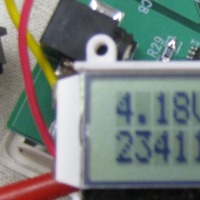
completely isolated when the switch is off) appears to have solved the problem. At long last,
we have a functional charge counter -- the below image shows the charge count as it is
updated by the counter.
April 21, 2010 (6 hours):
Unfortunately, yesterday's assessment of the charge counter's functionality was
premature. When connected to the battery, the charge counter circuit continues to become
incredibly hot. Unfortunately, there appeared to be no difference between the battery and
the power supply, even under heavy load testing. I replaced two flaky female power headers,
and clipped off the male battery header -- which later needed to be machined out and replaced
due to its being stuck in the via -- but nothing solved the problem. Finally, I believe
I have found a solution.
Because the only differences between the power supply and the battery were 1) the source
of ground in the circuit, 2) the simultaneity of connecting power and ground to the
board, and 3) the internal resistance of the power supply, I connected the battery to our
circuit through wires in a last desperate effort. To my surprise, this worked perfectly; the
charge counter counted in both charge and discharge situations, and nothing on the board
heated up. I still don't know whether this is due to the resistance of the wires or the
fact that both wires are connected simultaneously, but I have decided to simply take the
fact that the circuit works at face value. If necessary, we'll put a small resistance in
series with the battery for the final product.
April 22, 2010 (9 hours):
We demonstrated four out of our five PSSCs to David this afternoon: battery charging/monitoring,
sensor data communication over audio, finding current location via GPS, and saving data to
persistent storage. The only PSSC we are still unable to demo is navigation -- our heading
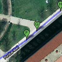
calculations are incorrect. However, we correctly save waypoints every 25 meters or so, as
evidenced by the Google Maps record of our demonstration trip.
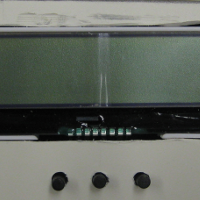
George machined out the top of the Gauntlet to make room for the LCD and pushbuttons.
The result is a very good-looking final product. Inside, however, there is very little
room for our ribbon cables and the free circuitry, like our GPS unit. We'll need to
secure those items very well.
Sean, Kelli, and I worked on the Gauntlet's user manual.
We took demonstration pictures, to which I added labels and some slight airbrushing.
I also formatted the final product.
April 23, 2010 (2 hours):
I started debugging the navigation algorithm. The problem is not with our trignometry;
it turns out that our east-west and north-south distances are unsigned when returned from
the functions, which puts all of our heading results in the fourth quadrant. I think that
a good way to return signed values without losing too much precision is going to be simply
returning signed long ints instead of unsigned short ints -- we don't need nearly that
much precision, but memory is cheap at this point.
Sean and I also put work into the longitudinal (east-west) distance algorithm. Previously,
we were using trigonometric functions (which took thousands of cycles per call) to approximate
the east-west distance between points. Now we use a cosine lookup table, which puts us
within two meters of our actual distance at a fraction of the timing cost, as long as the
user is within a kilometer or so of the last waypoint. This shouldn't be a problem for
us, as we save waypoints every 25 meters.
April 25, 2010 (6.5 hours):
The plan for today was originally to record video of the Gauntlet in operation. However,
the weather did not cooperate, so we instead worked to improve the emergency navigation
mode. Sean discovered one major bug (we reversed longitude and latitude in our direction-finding
algorithm) that, once fixed, allowed us to navigate reliably using the Gauntlet.
Afterwards, I worked to convert our audio output to a truly streamed solution. Previously,
our audio routines were blocking -- playing a sound file used up all of the resources available
to the Gauntlet, which meant that pushbuttons and other user-based output stopped working
completely until the sound stopped. Using the change notification interrupts available on the
PIC24F, I set up an interrupt to trigger every time the data request pin on the VS1011e switches
high. (This signifies that the VS1011e is ready for new MP3 data.) When an audio file is queued,
its filename is pushed into a circular buffer queue. In the main loop, the next filename is pulled
out of that queue, the file is opened, and its data is sent to the MP3 decoder. When the
decoder indicates that its internal buffer is full, the function saves the current state and
returns immediately to allow the main loop to service user functions like pushbutton polling.
When the data request line pulls high again, more data is sent to the decoder immediately. This
lets the Gauntlet respond to the user, even when audio is playing over the headphones.
WEEK 15 SUMMARY
Accomplishments: The team completed machining and placing the internals
of the Gauntlet so that we have an almost fully-packaged product. We fixed
the charge counter circuitry and checked off four out of our five preliminary
PSSCs. Sean and I completed the navigation algorithms for emergency mode (our
last PSSC), and I modified the audio subsystem so that the Gauntlet can respond
to user input while playing audio.
Weekly Work Total: 36.5 hours
Project Work Total: 246.5 hours
Week 16
April 26, 2010 (7 hours):
George and I did a quick test of our navigation functionality to ensure that it worked properly,
and we then demonstrated that functionality to David to complete our preliminary PSSCs. Currently,
the direction that the user should travel is communicated via a coded number -- 0 for straight ahead,
2 for right, 4 for directly behind, etc. We'll need to change this to a more user-friendly arrowhead
for our final product. David suggested that we use a 2x2 character arrow instead of a single ASCII
character in order to make the direction more obvious. We'll try to incorporate this into our design.
The team went outside to record the Gauntlet directing us around campus. We had a little bit
of trouble when our navigation software met up with buildings which blocked the GPS signal, but moving
to the Memorial Mall solved these issues. Again, a plot of our trip as shown on Google Earth matched our
path exactly. We also recorded a time-lapse of our charge counting ability, demonstrating the charge
count change when under normal operating load and when charging through the AC adapter.
Since all of our preliminary PSSCs are complete, I set to work turning the Gauntlet into a fully
functional, user-friendly device (instead of a demonstration tool). This means adding savable user
preferences, a fully-fledged menu system, and several other "perks" that the device did not previously
have. The menu system will be a state machine which is directed mostly by pushbutton input. Modes include
the main menu, a preference-setting mode (which allows the user to control volume, backlight settings,
and information output timing), normal mode (in which information is relayed to the user), and the emergency
naviagtion mode. I was able to complete roughly half of this menu system infrastructure before breaking
for the day; completing it will be a job for the rest of the week.
April 27, 2010 (8 hours):
Sean and I completed the vast majority of the menu system interface during our work today. Each mode
(Main Menu, Preferences, Normal, and Emergency) is now a menu ring, navigable by the left and right
buttons. The middle button selects an option, which either pulls the user farther down in the menu
system or exits to a higher level. The user preferences include the backlight settings (on, off, or
timed to the last pressed button), the volume, and the timing for the audio output (in 10-second
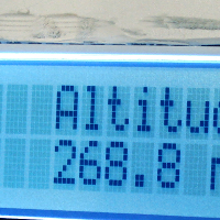
intervals from never to 250 seconds). A screenshot of the Gauntlet in Normal Mode, displaying the current
altitude, is below.
We recorded more of the footage for tomorrow's PSSC demo, capturing the Gauntlet's audio output
over speakers. Sean fixed scaling and division problems in my hastily-written battery code. While
attempting to play music over the Gauntlet's headphones however, we realized that all of the clips
which were played were noticeably detuned -- the pitch seems to bend up and down without reason
while an audio file is playing. We switched back to the original (non-queued) audio mode to check
whether or not my new queue code has caused the problem, but this showed that the audio distortion
showed up even when the microcontroller gave the decoder its full attention. This is unnoticeable
with the voice clips, so it may not be a problem for us, but I'd like to know why the MP3 decoder
is having this sort of trouble.
Finally, once the team had broken for the day, I decided that it was time to fix our airtime output.
(Up to this point, we had not been able to get the proper interrupts from our accelerometer, and since
this output is not part of our PSSCs, we decided to focus our efforts elsewhere.) It turns out that
our understanding of the datasheet for the ADXL345 was incomplete. There are several registers which
must be initialized to get activity output from the chip: one to start the measurement mode for the
accelerometer, one to enable the activity interrupt, one to set which pin the interrupt appears on,
one to set the threshold (in g's) for the activity interrupt, one to set the output parameters such
as interrupt polarity, one to choose which axes (x, y, and/or z) to include in the activity calculation,
and one to reset the interrupt once it has occurred. We missed these last two registers in our initial
perusal of the datasheet; without choosing axes for the activity interrupt, it defaults to "none of
them" and refuses to trip, and without resetting the interrupt register by reading its source from
the chip, only one interrupt will fire. Upon fixing these problems, and parallel problems with the
freefall interrupt, I was finally able to get the Gauntlet to trigger a breakpoint in MPLAB when
I batted it across the table. Soon after, I was jumping around in lab to set the sensitivity parameters
and record the airtime of my jumps, much to the amusement of onlookers.
April 28, 2010 (3 hours):
We presented our PSSC demonstration video today for the class. We were invited by the course staff to
present for either an ECE 270 or ECE 362 class on Friday, even though our video was somewhat difficult
to follow due to problems with the footage we had shot over the past two days. The battery footage is
fine (it simply displays the charge count decreasing and increasing in response to an AC adapter being
plugged into the device), and the audio output clip isn't bad, but the navigation portion is not
at all followable -- it jumps around and is terribly messy.
Sean and I continued to make changes to the menu navigation. Emergency Mode will now exit if either
1) a GPS lock is not obtained or 2) a safe point was not saved while in Normal Mode. In addition, we
made a few improvements to our navigation code, such as the "arrow" we use in the middle of the screen,
to make the direction the user should take more clear and increase usability overall. I had to leave
before I could debug one final problem my code caused (an error message displayed incorrectly on the
screen whenever a safe point was created), but Sean and Kelli were able to remove it and successfully
test the new and improved emergency mode.
April 29, 2010 (5 hours):
In the morning, Kelli, Sean, and I met to rerecord some the Gauntlet's audio samples. I brought a
nicer microphone into lab to try to stop some of the hissing in the Gauntlet's audio samples. I was able
to filter out the ambient noise in the lab to a degree, and I think the quality of the audio in general
is much nicer. In addition, Sean recorded phrases instead of individual words, which I believe will make
the final product sound more professional.
We decided that, as the Gauntlet's main functionality is complete, we would demo our final PSSCs for
David. Happily, all five of our PSSCs were adequately demonstrated, and the Gauntlet led David in a
path directly back to his initial location. To get to this point, some random bug fixes were required --
Sean and Kelli in particular discovered a divide-by-zero error in my timing code that caused the
Gauntlet to crash if audio output was turned off.
Since the PSSC demonstration footage for the GPS navigation left much to be desired, we went outside
the lab to reshoot. In the new footage, Sean takes the Gauntlet out for a stroll, gets lost, and has to
enter emergency mode in order to get back. I think the new "storyline" will, at the very least, add some
visual interest to our demonstration. It is proving difficult to find good ways to demonstrate a navigation
requirement.
April 30, 2010 (3 hours):
The team met before our bonus presentation to finalize the slides and the PSSC demo video. We did some
more editing on the video to remove some unneeded elements and help the video flow more smoothly. The
demonstration for ECE 362 went well (though all of the groups presenting were outshined by the presentation
for the D.O.G.). The video needs to be further streamlined, as I noticed some members of the audience
zoning out during our GPS PSSC demonstration, but overall I think our product was well received.
After the presentation, we headed back to the Memorial Mall to acquire the original path waypoints used in
our video. A Google Earth visualization of this path will be a much more intuitive way to demonstrate our
persistent microSD storage; we can read the waypoint file off of the Gauntlet again and put the results into
our PSSC video.
May 1, 2010 (5 hours):
The team met in lab to begin work on materials due Monday: the senior design report, the user manual,
and the team poster. George and Sean began working on the poster, while Kelli and I started with the
senior design report. After completing approximately half of the report -- which included the project
summary, summary of acquired skills, and a discussion of the influence of other coursework on our
design -- we switched places to avoid burnout.
We've decided to showcase the Gauntlet's design and use in our poster. We have included screenshots of
the Gauntlet in normal and emergency mode, and Sean modeled the device in one photo to prove that the design
is indeed wearable. We added Sean's initial CAD drawing of the packaging (which is incredibly close to
the final package design), our PCB layout, the final populated board, and a picture of the final exterior
of the product. We think these pictures will give the best overall view of what our product is and what
it took to complete it; now all our poster needs is a good layout. I'll put in some formatting work
tonight and tomorrow morning before we meet again.
May 2, 2010 (3 hours):
We met once more today to continue work on our poster and senior design report. I formatted
the poster and added pictures of the Gauntlet in operation; the result of our work is below.

In addition, we discussed changes to our user's manual. Portions of the Gauntlet's user interface
have changed in response to David's comments on our design; in particular, the emergency mode navigation
screens have been cleaned up and improved, with asterisks displaying the desired user direction and
some confusing prompts (such as "Save Waypoint") being replaced with more obvious descriptions. George
edited these changes into the final manual.
The senior design report is now finished as well. It is interesting to see a full summary of our work
this semester; we've come a long way since the beginning.
WEEK 16 SUMMARY
Accomplishments: The team demonstrated completion of our preliminary navigation PSSC,
quickly followed by all five final PSSCs. We recorded footage for use in our PSSC video
and were invited to give a presentation for ECE 362 students. Sean and I created a user-friendly
menu navigation system for the Gauntlet's user interface, and I implemented airtime
monitoring using the onboard accelerometer. The team also updated and completed the poster,
user manual, and senior design report.
Weekly Work Total: 34 hours
Project Work Total: 280.5 hours


