Kevin Hughes - Senior Design - Fall 2008 - Group 2
Week 01
Met as a team prior to class to discuss preliminary project proposal. Decided that the workout buddy should not include an mp3 player but should instead give an auditory cue during and after exercises. We also decided that it should be able to monitor and report on your heart rate, distance run, and number of repetitions for various routines. The following is a summary of the basic feature set we'd like to implement.
- be able to count/monitor/record exercise movement repetitions
- record stride/running information
- record/monitor heat rate and calories burned
- interface with a PC for workout "play lists" and to track/plot data
- record movement data for use with other software to display body movement for training purposes (such as rifle shooting and golf swings)
- be able to create new exercises on the fly and "add" them to the library of exercises
- use accelerometers to gather data. Must be removable (i.e. can be used on wrist or ankles, but not at same time)
- use a rechargeable battery (possibly charge over usb) in the main unit
- accelerometer monitor should be wireless
Accomplishments: Submitted preliminary project proposal.
Weekly Work Total: 2
Project Work Total: 2
Week 02
Met as a team prior to class to discuss project presentation. Set up PP and then reviewed specifications to prepare for presentation.
Met as a team after class to discuss final project proposal. Decided not to have as extensive of a computer interface. Altered our specifications to be:
- An ability to give audio cues to user
- An ability to transmit data from accelerometers over a wireless protocol
- An ability to learn new exercises based on user movements
- An ability to navigate a gui through lcd display using external inputs
- An ability to communicate to a base module via usb and upload data
Developed a block diagram, estimated the cost to be $250 and submitted proposal. 70 for lcd, 10 per accelerometer, 70 for transmitter, 5 for sd card reader, 30 for micro. Extras brought up the rest of the price.
Accomplishments: Submitted project proposal and gave presentation in class about design.
Weekly Work Total: 4
Project Work Total: 6
Week 03
Met as a team to discuss the results of our Final proposal and discuss possible changes to make.
In the evening I looked at possible revisions of our PSSC to meet requirements:
- Test 3 An ability to track and report through the lcd display the status of the batterys charge
- Test 5 An ability to recharge the battery and provide charge status to user
Also, I researched a more appropriate LCD screen to be used with our design and developed a block diagram of our battery recharging module and battery charge status indicator.
Accomplishments: Improved the PSSC's and looked into new parts for design. Also made block diagrams for battery related issues.
Weekly Work Total: 2
Project Work Total: 8
Week 04
We decided to take up the Villanova joint project. Have been working on getting information out of them as well about the project. We started the PSSC's but they are sill incomplete.
PSSC's are complete pending verification from Prof Meyer, they are as follows:
- 1. An ability to recharge and monitor an integrated (lithium ion) battery.
- 2. An ability to sense impact data using 3-D accelerometers.
- 3. An ability to generate an alert when a programmable impact threshold has been exceeded.
- 4. An ability to log/timestamp impact data on a removable memory device (SD card or USB memory stick).
- 5. An ability to remotely monitor real-time impact data and tune impact detection thresholds via an embedded web server.
Accomplishments: Switched to new project and generated PSSC's
Weekly Work Total: 5
Project Work Total: 13
Week 05
Attempted to meet with the Villanova team to talk about project goals and parts.
Looked into additional parts needed by the matchport. We will be needing an LED, 2k resistor, bypass cap, and a bulk cap extra than originally thought. ( I know i forgot about a bulk cap )
Met in the lab to finalize our component choices so that the Villanova team wouldn't be doing the project on completely different software. We begged them to concede to go with the PIC16 family of micros, and the following components came afterwards:
- Accelerometers from Measurement Specialists Inc (MSP1004-nd)
- 3 axis and +/- 250 g
- Wireless Adaptor from LANTRONIX (Matchport)
- Built in Embedded server
- serial to wifi conversion
- PIC16 family of micros, need to narrow this down based on i/o + mem + etc
- MAX8856 Battery Manager, and LI-ION battery rated ar 2200 mAh
In the evening I put together the beginnings of our power point for Design Constraints.
Outlined the Design Constraints report in the morning, and fleshed out the first six sections in the evening.
Completed a few more sections of the design constraints.
Accomplishments: Finalized a majority of our components, and completed PSSC's, worked too much on that paper which is still not complete.
Weekly Work Total: 16
Project Work Total: 29
Week 06
Sept 29, 2008 (2 hours) :
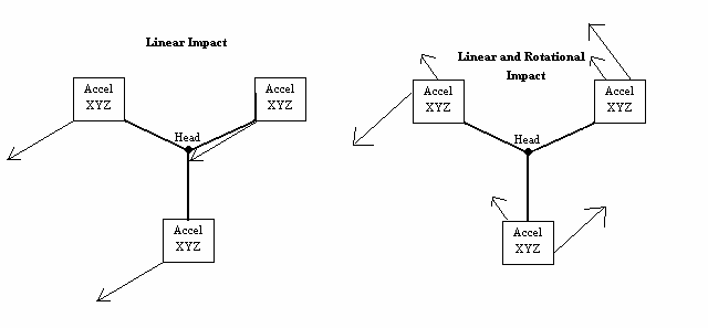
We reviewed the idea of using multiple accelerometers. After some debate, we decided to use 3 accelerometers. This change was made because there is still much study going on in the area of head injuries. Currently there are several popular theories that the sudden rotations of the head (as caused by an impact) may be more critical to monitoring head injuries than just monitoring impact force. This suggested we use 3, but I'm still not convinced we would have to have more than 2.
This change in our design has had an impact on our choice of micro controller. Our previous selection only had enough analog to digital converters to handle 2 3-axis accelerometers, and we need at least 9 ATD. Because our computational requirements can still be handled by the same family of micro controllers, we decided to stay within the PIC16 family and get the PIC16F887. This micro controller has more than enough ATD's as well as plenty of I/O pins to cover any of our programming needs. It meets our specifications in every aspect we reviewed.
Sept 30, 2008 (9 hours) :
Refined our part selection because when we called digi-key to get the 3-axis accelerometers we found out the part we were planning on using was obsolete. I contacted Villanova, who had selected and confirmed the parts availability, to see if they had encountered the same problem. They told us they had and the solution that they had come up with was to use a single 3g 3-axis accelerometer coupled with some force dependant resistors. Adam looked at the numbers for the parts Villanova had selected and after some number crunching determined that the parts were not able to register a large enough impact. Adam concluded that 1 pad they were using could only handle about 20k lb where a 90g impacts would register over 100k lb
We then spent several hours looking for another 3-axis accelerometer that measured up to 150g. We were unable to find such a part for under $500. In order to alleviate high costs, we decided to use 3 single axis accelerometers mounted very close together to mimic a single 3-axis accelerometer. We found several single axis accelerometers that registered high-g amounts. However in order to make our design simpler we need to have 2 X axis accelerometers and 1 Z to mimic the behavior or a 3-axis without having some unusual fabrication methods. We are going to use the Freescale line of accelerometers, which all have identical electrical characteristics (this is a good thing!).
Because we need to now measure 9 atd and the will be in serial we needed i higher clocking capability. This lead to the change to the PIC18F45K20. This processor also has the added advantage of requiring less power and has the potential to run at a much faster rate. This makes this processor a better choice than our previous selection.
Oct 1, 2008 (2 hours) :
Today we met to discuss the change of processor and accelerometers. We agreed that the parts met our requirements and that we should plan to use the new parts. We also reviewed my power point presentation. Everyone seemed satisfied
Oct 2, 2008 (7 hours) :
Today we met and worked to finish up the homework due friday (tomorrow). I worked on finishing up the Schematic for the matchport. I had to scour the matchports user guide (and integration guide) and figured out what each pin on the matchport would be used for. This needs 4 pins for just the email and pager alert system, a tx and and rx, an led port for the activity notification, and of course the power/ground pins. It should be relatively simple.
A rough draft of the schematic is almost complete. All that is lacking is the power circuit. We plan to meet up tomorrow morning and talk to Karl about possible ways to implement a power circuit for our design.
Oct 3, 2008 (2 hours) :
We began by inspecting the homework due, and made very few minor adjustments. One of the big problems we are encountering is trying to get power to our components while the helmet is plugged in and charging. This would be good because we would like to allow the user to access the web server and configuration while the helmet is plugged in. To accomplish this, Karl suggested using 2 power MOSFET's to act as a switch between 5V DC from the wall wart and 3.7V DC from the battery. This switching would occur whenever the helmet is plugged in. In addition, we modified out power circuit to include an LDO to drop the voltage coming out of the battery to the 3.3V we need for most of our components.
This slightly complicates the matchport schematic because we wanted to include one of the LDO's in it.
Accomplishments:
-Modified design to use 3 acceleration test points as opposed to 1.
-Changed from using a single 3-axis accelerometer for our test point to using 3 single axis accelerometers to synthesize a 3-axis.
-Changed our microprocessor to the PIC18F45K20.
-Finished up rough draft of schematics
Weekly Work Total: 22
Project Work Total: 51
Week 07
Oct. 6, 2008 (2 hours) :
We put time into discovering how to use Layout. It seems ok but the footprint creating is giving me trouble.
Oct. 7, 2008 (10 hours) :
Today we talked with professor Meyer to get a better hold on our power circuit. Professor Meyer suggested that we don't use power MOSFET's but instead use zener diodes for our switching circuit.
Once we got to the lab, we changed out all of our power circuit components. With the help of Karl, we reworked the circuit draw power as illustrated below:
LDO : TPS75733 This component is mainly used to efficiently drop our 5V wall wart voltage down to a voltage usable by our boost and buck boost components.
Buck Boost: LTC3440 This regulates our source voltage to 3.3. A single LTC3440 can produce up to 400 mA, which does not meet our power requirements, thus we have one LTC3440 to power the Matchport (which draws 360 mA max) and one to power the Micro controller and SD reader (drawing about 250 mA max).
Boost: LT1303 This converts our incoming voltage to 5V for use by the accelerometers.
Oct. 8, 2008 (6.5 hours) :
We reviewed adams PP. We rethought out the power estimates to run for ~5 hours.
1 Accelerometer = 5V @ 6 mA = 30mW
9 Accelerometers = 30mW * 9 = 270mW
5 V converter (better than 80% efficient) = 270mW/.8 = 337mW
Micro = 20 mA * 3.3V = 66 mW
SD = 200 mA * 3.3 V = 660 mW
3.3 V converter (better than 90% efficient) = 726/.9 = 807 mW
total Power (w/o WiFi) = 1144mW
WiFi = 360 mA * 3.3 = 1188mW
3.3 V converter (better than 90% efficient) = 1188/.9 = 1320mW
Total power estimate = 2508 mW
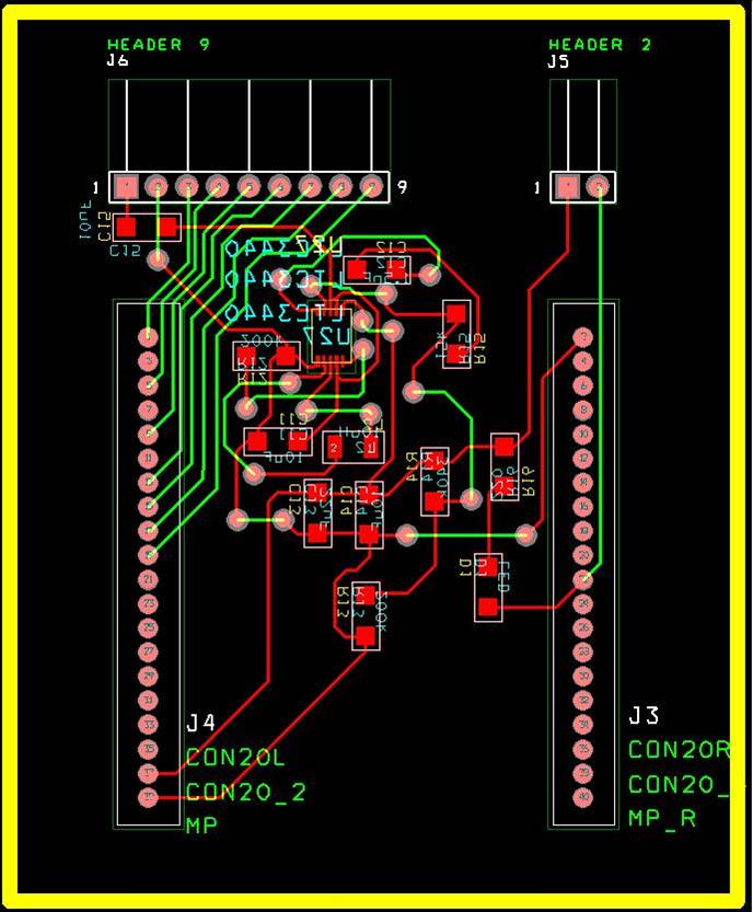
Oct. 9, 2008 (8.5 hours) :
We met and updated the schematics. We added headers to everything so that the separate PCBs could communicate and share power/ground, also for the testing.
Having completed the schematics, we moved on to fill out footprints for all of the parts. With the footprints done, the components were layed out in Layout and a quick auto route was completed to give us a rough idea of what a final circuit might look like. In the future, i would suggest never doing an auto route. They aren't pretty when they have completed, even for our simple PCBs.
Accomplishments:
-Power schematic updated
-PCB Layout presented
-Rough Draft PCB's created
Weekly Work Total: 27
Project Work Total: 78
Week 08
Oct. 13, 2008 (5 hours) :
Worked Matchport PCB. I started from scratch about 3 times and rewrote the Matchport footprint to be a single unit instead of two separate sockets. The LTC3400 is now complete. It was a little rough to keep the caps in close, but it looks good.
Oct. 13, 2008 (7 hours) :
Once again working on PCBs to get a better layout for them. I finished laying out the Matchport, however it did require another starting from scratch because i had a few errors in the initial setup of layout. I still have to make the lines thicker and fix a few things with footprints.
Oct. 14, 2008 (6 hours) :
Today we had a meeting with Karl and professor Johnson for our Progress briefing. They believe we are well on our way however there were several changes that needed to be made. The Matchport needs to have thicker traces mainly.
After making changes to the Matchport PCB, I outlined the slide for our group presentation over our project. Ill do the intro and the design considerations. And the Software considerations so far. I'm thinking about playing with vectors some. My initial stuff looks like this.
Oct. 15, 2008 (3 hours) :
We put together the presentation. One of the major notes on all of our boards is that we need to review our capacitors to ensure the correct type are selected for the right areas, it appears as if we completely spaced polarized vs non polarized selections. The other big suggestion was that we should consolidate our SD and Power PCB's onto the micro controller PCB. We started working at this ad noticed that that SD PCB is the same size as the header to the SD card. This should be doable.
Accomplishments:
-Finished a good but not final draft of our PCBs
-Prepared and gave presentation on current status of our Design
-Began implementing new version of Micro/SD PCB
Weekly Work Total: 21
Project Work Total: 99
Week 09
Oct. 20, 2008 (5 hours) :
I watched and tried to help as Mike worked on the Micro/SD PCB. I was able to make several significant contributions when it came to optimizing some of our paths. I also looked into making sure we had the correct footprints for the newer parts. I also eliminated the usb lines going into the power select lines since they aren't going to be used. (i asked Prof. Ferguson about that before actually doing it. He approved it and backed my logic with his own).
Oct. 21, 2008 (10 hours) :
Had to re update the Matchport because some of the capacitors were not the correct footprint. Now we have capacitors that are bigger than some of the headers we are using. For the micro pcb, we put all of the components for the power IC on one side of the board this allowed us to place one power IC directly on top of another power IC. This allowed us to minimize the size of our board just a little.
Oct. 22, 2008 (6 hours) :
We tested the Matchport and the Accel PCBs on the web site and found them to work. freedfm to see how whether the board has any major errors. I have not heard back from freedfm yet.
There were a few changes we had to make to the Micro such as trace enlargement and new capacitors (this was a huge problem because we had some of them placed very close and tight to the micro).
Oct. 24, 2008 (2 hours) :
Today we received a large portion of our parts. We received:
2x Charger IC (MCP73838)
2x Coulomb Counter (DS2740U)
3x Buck Boosts (LTC3440)
7x X-axis accels (MMA2301)
4x Z-axis accels (MMA1212)
2x SD Connectors (HR1940CT)
4x Or gates
2x Boost (LT1303)
We still have yet to receive:
micro controller (PIC18F45K20)
Wireless Adapter (MatchPort)
Battery (5169UBBP01)
Connectors
Passive circuit components (these need to be ordered)
Chuck told us that he lost all of his ordering work when the computer crashed. Hopefully the rest of our components will be coming in soon.
Accomplishments:
-Finished our PCBs
Weekly Work Total: 23
Project Work Total: 122
Week 10
Oct. 25, 2008 (5 hours) :
Began working on the Software Design Considerations HW. Mike and Adam helped me outline the report. I also made the power point for the class presentation.
Software Design Considerations
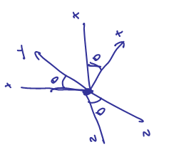
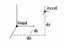
I also made these rough pictures to help analyze the math.
Oct. 26, 2008 (10 hours) :
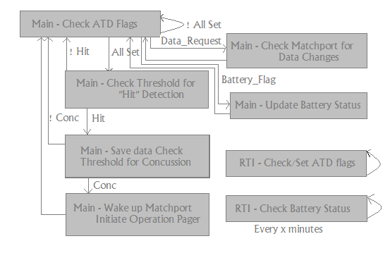
Worked a lot on the paper. I now have a much better Flowchart for code (thanks to Drew)
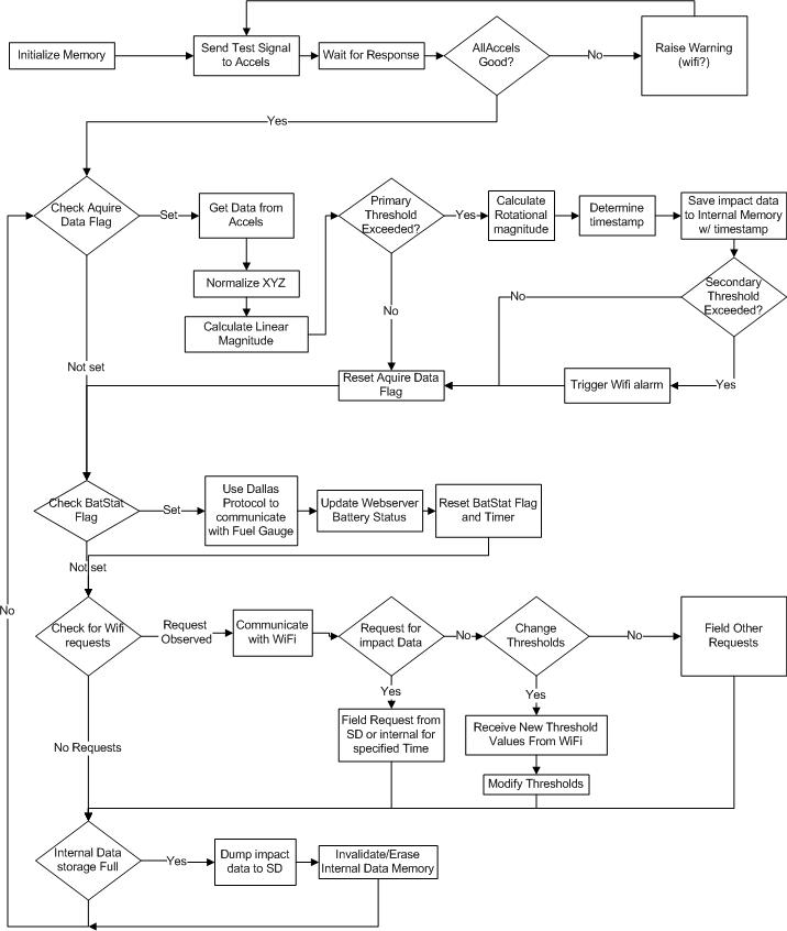
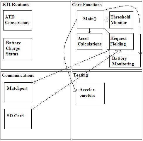
And I created a Code Hierarchy.
Oct. 27, 2008 (3 hours) :
Finalized the HW9 Document.
I cant seem to get it to put in my formulas properly, so feel free to check out the document to see the formulas I am using to calculate the Resultant and the Moment of the impacts. But here are the bad looking ones:
RX = A1X + A2X + A3X
RY = A1Y + A2Y + A3Y
RZ = A1Z + A2Z + A3Z
R = (RX2 + RY2 + RZ2) ^ ½
MX = A1X*D1X + A2X*D2X + A3X*D3X MY = A1Y*D1Y + A2Y*D2Y + A3Y*D3Y
MZ = A1Z*D1Z + A2Z*D2Z + A3Z*D3Z
M = (MX2 + MY2 + MZ2) ^ ½
Week 10 Summary
Accomplishments:
-Finished HW9 and made software advances for the vector calculation
Weekly Work Total: 18
Project Work Total: 140
Week 11
Received our first PCB! (Micro controller PCB)
Also, we installed the software to test the development board
At this time we are unable to get it working correctly, but it is a start.
Mike and I went into lab to work on getting the development board completely working.
We made our first Hello, World! test and then went to playing with LED
The LED test was successful, We are now looking into initializing SPI and maybe using it to send text to the LCD on the development board.
We received our other 4 PCBs today
I tested both of them and confirmed all nets are connected. We received our connectors and tested them, they fit. Drew is going to take care of the soldering of the PCBs sometime this week while me and Mike continue to code in SIM mode of the development board (we are doing this because the ports of the micro that the development board uses are different than the ports that our micro controller uses)
I beefed up the test code for the development board to include an pushbutton functionality as well as an exhaustive led light show. After implementing these i looked into the libraries for SPI, ATD, LCD, and UASART. The library documentation can be found at: Library Documentation
I began writing functions to read/write to the ATD.
Accomplishments:
- Received and verified all of the PCB connections.
- Obtained basic understanding of how the Development Board works.
- Located and began writing code for more advanced features of the micro.
Weekly Work Total: 14
Project Work Total: 154
Week 12
I looked into the ATD library, using their example code (for another processor) I was able to get it working for the PIC18F4520 with only a few modifications.
I was then able to get ADC_CH0 and ADC_CH1 working in series and have mathematical calculation using both of them. This is significant because our final go will have 9 ATD that need to be read and then calculations done. With the progress made i feel confident that it will not pose a problem.
After helping drew with the last of the accelerometer soldering verifications. I was able to successfully hook an accelerometer up to the development board and then see the accelerometer work by measuring both negative and positive accelerations on all 3 axis'. (I need to do this for the other 2 accelerometers as well)
I looked into adding math.h so i could calculate the resultant vector from the 3 inputs of just one accelerometer. I then calculated the average value with 1 accel because i wanted to see how much memory it took up. The memory totaled pretty high at 29k (of 32k):
This is simply unacceptable. Each ATD Conversion takes almost 6k of memory to use and we need 9 of them! This is 54k of memory, and we only have 32k available. I am going to try and figure out why an ATD conversion occupies so much memory.
Mike and I identified why the files were taking up so much space. Actually, it was that we were looking at the wrong file. we were looking at the object file made by the compiler because the software wasn't generating a hex file. Now that we have corrected that and have a hex file we decide to implement some changes to reduce the size. The changes are that we implemented are:
We began talking about what we need to make the rest of the project work. We forgot to buy a micro SD Card, so we need to get on that right away.
I looked into SD Cards to buy and decided that research isn't my thing. Ill save it for reading packages at Wal-Mart or Radio Shack. I began writing code that would use SPI to check the thermometer that is installed into the development board.
Drew and I met today to get the power circuitry completed in the Micro and the Matchport PCBs. We managed to get the matchport soldered up, minus a few components, but the entire power section. We then tested it to see if it generated 3.3V from any inputs given. It generated 3.24V in the range from 2.5~4.0 volts. We think that once the rest of the components are soldered on that it will regulate to 3.3V as promised. We still need to work on the Micro PCB and finish up the Matchport.
Accomplishments:
- Finalized ATD on the Development Board.
- Verified that Accelerometers work on the PCBs (except the status).
- Began working with SPI.
- Soldered the power section onto the matchport and verified its functionality.
Weekly Work Total: 16
Project Work Total: 170
Week 13
Mike and I added interrupt functionality to the USART, and verified that it works correctly, we now believe we have what it takes to drive RS232 communications.
Adam and Drew soldered the power components onto to Micro PCB while we handed parts to them or talked about orientation problems. We still have some more to do though.
We got the Matchport up and running, it connects to the PC now via an AD Hock connection, I haven't put any security on it but i did change the default password and SSID that it broadcasts.
I'm planning on looking into putting a web page onto the matchport.
I started off polishing the security of the Matchport, it now uses wep with a password that is visible from our lab station. Also, i noticed that we need to use one of the configurable pins for resetting the wireless settings to default. Its an option that is selectable from the online configuration menu. I also set the matchport to have a static ip address so it wont change every time we turn it on.
After that, i set up a really basic web page on the matchport that displayed some text.
After I demonstrated basic functionality, Mike and I used a java applet found on the lantronix technical help web site, it will mirror any communications to the matchport on the web site and allows us to send data to the micro from the web site
We realized that our way of thinking was wrong. You don't store variables on the Matchport, or communicate with the matchport, you communicate through the matchport and store defaults on the micro and/or the web page The matchport is really just a tunnel for communication.
We tried connecting the micro pcb to the mplab software but were not able to get it working correctly. I spent the evening trying to figure out why.
My first route was to make sure voltages are what they need to be. For all of the power circuitry the voltages are correct. I then made sure that we were connecting the board to the mplab device correctly. My derivations are:
I checked the micro data sheet and the pins are correctly inserted in the right places. My next course of action is to verify that the voltages are as follows:
- pin 1 = Don't care
- pin 2 = 2v
- pin 3 = 0v
- pin 4 = 0v
- pin 5 = 5v
- pin 6 = < .5v
The above data is from the lantronix help site.
Accomplishments:
- Got everything ready for programming chip.
- Matchport is up and running with web site
- Began figuring out how to program micro
Weekly Work Total: 21
Project Work Total: 191
Week 14
I looked into the Voltages and they were being outputted correctly. After that I noticed that we had a really long cord. Adam cut the cord from about 4ft to 4 inches. I then spliced the two pieces together and went to verify that it was working. I noticed that the yellow (PGC line) wasn't connected at both ends. It turned out that the pin wasn't placed properly so there had not been a connection between the PGC on our board and the PGC on the ICD. I took the pin out, re-set it, and it now works. Our device connects correctly and programs. The erase program memory, verify erase and verify programmed works properly. However when i switch the device over to debugger, i get errors, so i cant verify that it is working on the board yet. I'm not even sure the debugger is supposed to work, we just need to run tests on it.
If debugger doesn't work then my first step is going to be making the connection between the micro and the matchport and verifying that serial works. Because the matchports web server is a mirror of what goes across the serial, if I send something over the serial on the micro i can verify its working from the web site
If the debugger is supposed to work though, Ill check out this site for more troubleshooting in the matter.
Drew and I came in and made a cable from the micro to the matchport. My first attempt at running the matchport from the micro failed miserably, the following was my pin layout:
Matchport Micro Actual Matchport
- pin 1 = PWR PWR GND
- pin 2 = GND GND PWR
- pin 3 = RST RST
- pin 4 = Tx Tx
- pin 5 = Rx Rx
- pin 6 = C1 C4
- pin 7 = C2 C3
- pin 8 = C3 C2
- pin 9 = C4 C1
This shows quite accurately how i managed to burn out the LTC3440 of the matchport power circuitry. The PWR and GND pins are switched on the schematic. After the point i do remember we moved them during the PCB design because it made the layout easier. I had never soldered before this point, so i learned how to remove and put on a chip. Removal was pretty easy, however i asked Brian from team1 to help me put it on. He attempted to solder it on but was unsuccessful and left the chip looking bad. I got over my fear of soldering and sat down to fix up the pins that needed it. The matchports power system was repaired! I then hooked up the matchport to the Micro for take 2.
I found out that the micro doesn't power the matchport properly. The voltage is right at the lower threshold, so the matchport will power up, but at random times it will reset because it needs more power than it has available. This can be a problem in the final design. Also, our RS232 communications must not be properly configured because we argent getting the right data back from the micro.
With that, I'm off for break and will be back saturday. (Also I cant forget to cut the traces coming from the MCLR pin (pin #3).
Accomplishments:
- Got the ICD connected and programming the micro.
- Verified that the Matchport isn't recieving communications from the Micro.
- I went home for Thanksgiving break so nothing else accomplished.
Weekly Work Total: 10
Project Work Total: 201
Week 15
Mike and I worked with the programing. We have a problem where we can program the board but it simply doesnt run. I spent most of my time making changes and testing. We removed a diode on the PCB that improved the voltage to the board by 1V (this fixes the problem where the matchport would fail and restart occasionally) We also found out what was wrong with the matchport. I updated its firmware and reinstalled the website for configuration online. With that I identified some of the problems that might have been causing the rs232 to not work, after this failed Mike and I went a a much simpler program to toggle port pins.
This test is still not working. We are attempting to figure out why.
Mike and I continued to work on finding out why the micro controller is unresponsive. (before class) Also, I offered feedback on the accelerometer placement and asked for one accelerometer to be moved to the edge of the helmet for convenience.
To facilitate identifying the problems, we:
Then we tried toggling portD on and off. This helped us determine we were running the code at the correct freq of 16MHz and then we tried to get timers working. After countless hours we couldnt get the timers running correctly, they appeared to force portD high even without and code to do so.
We took a break and worked on the USART, on out first try we got gibberish. more like
XX XXXX XX XX
We deduced that the matchprt was interpretting data much faster than the micro was sending it so we upped the speed. This gave us
XXX fff~FFX
We upped the speed again and got perfect outputs!
0123456789ab..zAB..Z
With this success we called it a night. Tomorrow morning we are going to get the micro to regurgitate anything that the webpage sends to it right back. This will allows us to create user defined outputs.
Mike and I started off getting the micro to recieve transmitions from the webpage. We then parsed these inputs to recognize commands that would Set one of our 4 threshold values, or request one of our 4 variables. We successfully have the micro storing and sending data now.
We moved the threshold values into eeprom memory and thy successfully load upon startup.
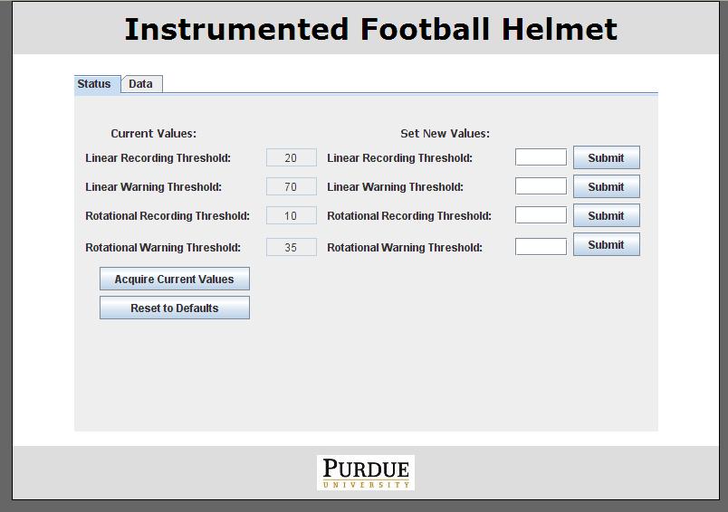
We then updated the website on the matchport to be more professional (and to prevent people from exploiting the unlimited access to the send buffer). I have pictures:
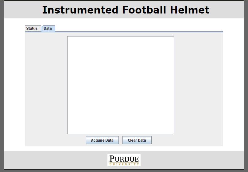
While I was looking Mike added in support for timer2, and we integrated that into our command lines. It can be toggled using the matchport.
We began the Product Support Manual by adding tutorials for connecting to the helmet, changing settings, and troublshooting errors.
Our next step may be to make the new webpage fully functional. We then will get the timer working, then the ATD, then the attery monitor and SD Card.
I set up the accelerometers such that their pins from the micro are correctly configured to enable proper use. After this, i wrote a test for each accelerometer that determines if the accelerometer is operating correctly. These correctly determine the status of each cluster of accelerometers and then tells the matchport if their are any problems.
I did find one error though. It looks as if our micro has 4 pins reserved for porte, however they cannot be used by the micro. We have pins 1,2 of porte for the status and test lines to accelerometer 3. We will have to cut these traces and flywire another pin to them.
We spent alot of time trying to incorporate the microchip SD card library into our code, however we found out that the library takes up 30k of program memory and 2.1k of data memory, both of these values exceed our total available memory. We wasted alot of time working on this so we decided to call it quits afterwards.
We wrote accelerometer code that would check all of the values and do proper value changing on them. atm we have the axis coordinated as follows:
Then we went to work on the SD card again...
Accomplishments:
- Got Matchport communications working.
- Built new webpage.
- Made Variables writeable on the fly.
- Added code that tests accelerometers.
- Added code to evaluate the accel data and detect threshold values.
Weekly Work Total: 55
Project Work Total: 256
Week 16
We continued making small optimizations to the accelrometer calculations and the way we store values into eeprom. Also, we tried to use different techniques to identiyfy how the SD card communications were working.
We decided to hook up the CD Card traces to the logic analyser to further perfect our communications. At this point we completely updated the gui to support additional features, and i coded a the battery monitor to be used by the software. My battery monitor can be reset by the webserver and stores the curent estimated battery charge into eeprom every 5 minutes. at this rate, it will take about 2 years of continual use for this device to go bad...
We perfected the battery monitor and added that functionality into the webserver. Also, we researched additional techniques to talk with the SD Card, I looked at the Sandisk site to see if sandisk cards supported SPI, their technical support is lacking, however i was able to find a compatablility page which looked to be terribly incomplete. (no help found there). We started to manually code the lines because we cant figure out what the problem is.
We came in early to find that Adam had made a huge breakthrough in how the SD Card needed to be configured. We cut a few traces and re-routed them to find out that we have SD Card communications. We can initialize the card, but need to figure out reads and writes.
In the morning we looked into why the SD Card wouldnt be writting and reading properly. I added in a larger buffer size (512) so that we could use the whole buffer, however this didnt solve the problem. We then began looking into the manuals to see if there was a specific sector we knew for sure was read/write enabled.
Mike and I solved the readign and writing problems by modifiying the linker script to not include a 512 buffer. Apparantly, the space we reserved was read-only memory so we could never change anything in the buffer... We are using a smaller buffer located in read/write memory. This new buffer is 64 bytes long. We then tested the full functionality of our helmet while it was battery powered. We noticed impacts were getting past us, but this was because we were testing it only a few times a second. We increased this to 400 times a second (the maximum freq of the accelerometers) and found that we didnt miss anything. This however possed a problem with our calculations. Because the calculations took so long, we had to take the max measurements, over an interval. our first try was 1 sec, but we changed it to be .5 secs. Then we perform the calculations outside of our main loop which improved our computation time.
Accomplishments:
- Obtained access to the SD Card and began working on coding in R/Ws.
- Updated webpage.
- Coded in battery monitor to keep realtime charge accumulation.
- Upgraded the response time of the helmet to not miss impacts.
Weekly Work Total: 47
Project Work Total: 303
Week 17
We finalized the SD Card and functionality, revised papers for the final paper, made changes to the java applet on the webserver, and discussed the final presentation.
Accomplishments:
- Successfully completed the Instrumented Football Helmet
- Began working on the final deliverables
Weekly Work Total: 5
Project Work Total: 308