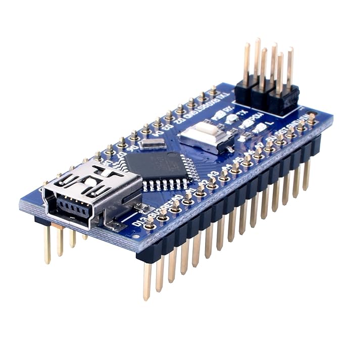
Our SensorKit is built based on Arduino microprocessor, which include 5 types of sensors at the moment. It is built to be a wearable and wireless bio-signal-sensor kit.
Our purpose is to use this sensor to collect the bio-signals (including skin temperature/conductivity, arm/hand motion, pulse rate and muscle intension) of students in real-time. Our target is to make it small, light and comfortable to wear.
The total cost for the current design is around $150 each. Based on the robustness of the sensors and the battery life, the reliable time is around 2 hours.
* Note that these instructions are PC/Windows-orientated. *
Sensor Descriptions
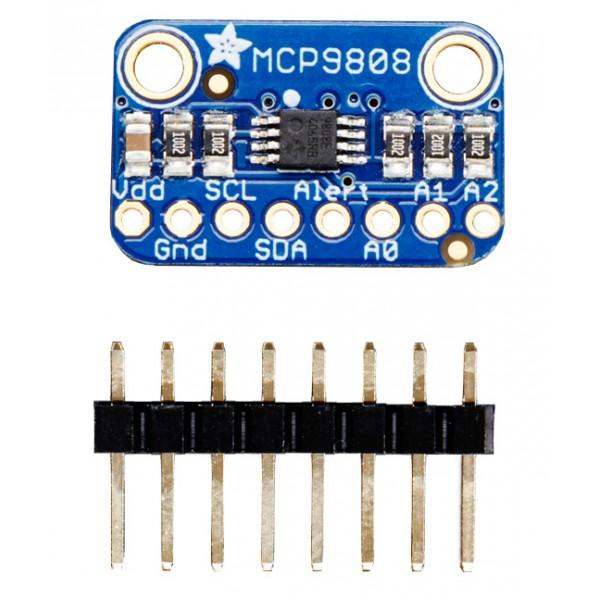
Temperature Sensor
MCP9808 High Accuracy 12C Temp Sensor Breakout board
Manufactured by: Adafruit
Part #: 1782
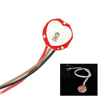
Pulse Sensor
Pulse Heart Rate Sensor Module for Arduino - RED
Manufactured by: Asiawill
Galvanic Skin Response Sensor
Grove - GSR Sensor
Manufactured by: Seeed
Part #: 101020052
Bluetooth Connection
Bluetooth Seiral Pass-through Module Wireless Serial Communication with Button for Arduino
Manufactured by: DSD Tech
Part #: HC-05
Other Materials Needed
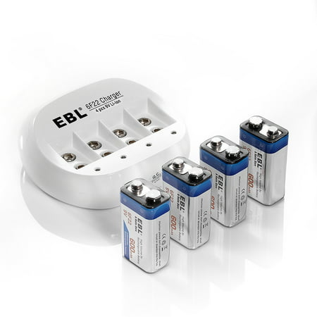
Rechargeable 9V Batteries
We chose: EBL 4 pack 9V 6F22 600mAh High Volume Lithium-ion Rechargeable 9V Li-ion Batteries
Manufactured by: EBL
Part #: 6F22
Battery Connector
Faux Leather Housing T Type Clip Connector for 9V Battery
Manufactured by: IDS
Hook-Up Wire Spool Set
22AWG Stranded-Core 6 x 25ft
Manufactured by: Adafruit
Part #: 3111
Wrist Brace
Manufactured by: Mueller
Part #: 86271
Velcro Strap
Black Nylon Onewrap Velcro Strap, Hook and Loop, 1/2" Width, 5' Length
Manufactured by: Velcro
Part #: 1801-OW-PB/B
Adhesive Velcro Patches
Hook and Loop Type Reclosable Fastener Shapes with Rubber Adhesive, Black, 7/8" x 7/8", 12PK
Manufactured by: Velcro
Part #: 6PXV4
You will also need other materials such as thread and needles to attach the sensors to the velcro tabs as well as to sew components directly to the glove or hat, scissors, solder and a soldering iron for making wire connections, and wire cutting/crimping/stripping tools.
Description of Data Flow
Steps to upload
1. Disconnect battery
2. Disconnect Bluetooth
3. Connect Arduino to PC with a mini-usb cable
4. On the Arduino IDE, set up the port and board on the tools menu bar (You will need to know which port is the Arduino connected to and which Arduino board you have)
5. Upload
6. Disconnect Arduino from PC
Steps to collect data through the Arduino IDE (With Bluetooth)
1. Connect Bluetooth (RX0, TX1)
2. Connect Battery
3. Turn on PC Bluetooth
4. Pair PC with Arduino devise, the name of the Arduino devise is HC-05 and the pin is 1234
5. In the Arduino IDE, set up the port (again) on the tools menu bar, the board should be the same
6. In the Arduino IDE, open the serial monitor from the tools menu bar
7. The Arduino will show some data configuration on the serial monitor, please wait
8. When the message “We are ready to go, please enter 1 and send to start” appears on the serial monitor, please enter “1” on the upper writing box and the click on “send”. This will collect 1 datum of each sensor.
9. To collect more data, one at a time, keep sending 1s to the Arduino. To collect multiple data, send “2” to the Arduino.
Steps to collect data through Python
1. Set up the Arduino and sensors.
2. Connect the Arduino to the computer (if using Bluetooth, please use the first 4 steps from the section above)
3. If the Arduino does not have the sensorkit software version you are going to use, please upload it to the Arduino by following the “Steps to upload” section.
4. Open Spyder (Python 3.6) and the file “serial_real_time_graph_test.py” (This is a developing process, it is still a test and the software is not for release version yet). The script sets up the connection with the Arduino and for every data collecting cycle: a) reads the output from Arduino, b) shows the output in screen and writes it in a txt file, c) process the data received, d) if figures are requested (with a flag at the top of the code), creates or updates the figures. At the end, the script saves all the figures in a “figures” folder. The script can be stopped at any time with a keyboard interruption (ctrl+c). This script will need the other scripts below. They should be in a “lib” folder, for more information about them please see the file.
a. func_cd # Provides the function to change directories with relative addresses
b. func_data_read # Contains the functions to read sensor-kit data
c. data_plot_scheme # Contains the functions to create, plot (in real-time) and save sensor-kit data
5. Run the file in a dedicated console. You might have to change the graphics backend configuration of the IPython console. To do this in Spyder go to a) tools, b) preferences, c) IPython console, d) graphics tab, e) in the graphics backend section select “Automatic” from the drop-down menu, f) click OK.
6. Collect data
7. The program exits when it has collected the number of data you specified in the “num_data” variable.
Fast Data Acquisition Procedure Fast Data Acquisition is a modified version of the python data acquisition scheme which increases the available data rate, but also makes the resulting text file more difficult to read. A special set of python tools has been created to capture data more quickly.
1. Upload the “fast_sensor” Arduino code to the Arduino.
2. Open Spyder (Python 3.6) and the file “fast_sensor_from_COM.py” Ensure the indicated port is accurate, as indicated by the device manager or other port monitoring service. Baud rate should be 230400.
3. A file dialog will appear. Select a directory to save the acquired data. The data is saved as a raw output .txt file and an interpreted .csv file with a more usable organization, both with a filename of the time and date.
4. After selecting the directory, the computer begins logging data and will continue to do so until a Keyboard Interrupt is sent. Always end the data acquisition session with a Keyboard Interrupt (Ctrl+C).
The data is transmitted in ASCII as three-column, tab-delimitated text with \r\n line separators:
data_channel \t timestamp \t value \r\n
data_channel is an unsigned integer indicating which sensor’s value and time is being transmitted. Each sensor (and axis of sensor if applicable) has a unique data_channel number.
timestamp is an integer indicating milliseconds since Arudino was last reset.Resets occur at a power cycle, pressing the reset button, or reconnecting to the serial bus. It overflows after about 90 days of continuous use.
value is the value of the indicated sensor at the indicated time. Floating point data is converted to text with precision at the hundredths before transmission.
There is also channel configuration metadata that is transmitted at the top of the file, also in ASCII, three-column, tab-delimitated text with \r\n line separators:
data_channel \t sensor_description \t units \r\n
data_channel is the same integer used in data transmission.
sensor_description is a string indicating which sensor is using this channel
units is a string indicating the units for this sensor
Upon shutdown with a keyboard interrupt, the Python interpreter tool will generate an easily importable csv file containing each data point and its associated timestamp for each channel. The header row contains a reformatted version of the sensor configuration metadata, with each datum separated by a pipe “|”, ending with either “timestamp” if this column has timestamp data or “value” if it has value data.
data_channel | sensor_description | units | {"value","timestamp"}
Data is then sorted into each column as indicated by the header. Value and timestamp data is always pairwise, with corresponding datapoints always on the same row.
How to Build a SensorKit
Within our study we created two different versions of our SensorKit Wearables: a glove and a hat. The original device was built as a wrist glove, and was later rebuilt as a hat in order to test different areas of the body for signals of stress.
Use the tabs below to view the information pertaining to each device.
Schematic for SensorKit
Glove SensorKit Details
Please see the Schematic Tab for connections between the sensors and the Arduino.
Glove SensorKit 1.0
Glove SensorKit 2.0
Hat SensorKit Details
In order to create a Hat SensorKit, one will need to obtain a ballcap (or any type of hat) with a fabric strong enough to support the sensors that are going to be attached to it. Before assembly of the SensorKit onto the hat can begin, however, it is imparative that the sensors and boards are tested to make sure they are operational.
* All Hat SensorKit connections can be viewed on the schematic. NOTE: Not all sensors are used in the Hat SensorKit. *
Please Note: the SensorKit boards are attached to the hat via Velcro patches, making it easy to detach and reattach them to different areas of the hat in order to keep the wires separated. Future versions will have the wires and electronics encased.
Hat SensorKit
Steps to Epoxy Sensors
This portion of the assembly is optional and by no means necessary, however by applying epoxy to the sensors in your sensor kit you are protecting them from wear and tear, as well as preventing a malfunction do to moisture getting into the hardware.
!! Before you get too far ahead, we recommend attempting this step after you have already made the wire connections. This is so the holes where the connections are made do not get filled, and it also helps to solidify the placement of the wires.
You can find epoxy kits online or at your local craft store. They are easy to use, however you may want to wear protective gear (such as a breathing mask) for this process, as the chemicals give off strong fumes that can prove to be irritating.
Step 1: The first step of this process is mixing together the resin and hardener to create the epoxy solution. Once these two are mixed together, it is essential that you apply the epoxy to the sensors right away, or it will harden and become unsuable. That being said, be sure to follow the measurement instructions included with your epoxy kit and only mix together a small amount of the fluid at a time.
Step 2: Once you have your epoxy solution mixed fully, begin to prepare your sensors for coating. It is essential that they lay flat during this proccess, as the Epoxy (though thick) is a liquid and will move toward one side or the other of the surface. As stated before, this step is probably best completed after the wire connections have already been made with the sensor boards. This is so the necessary holes don't become filled with epoxy, rendering them useless and unable to form a proper connection.
Since most of the sensors have uneven undersides due to solder and connection points, it can be difficult to get them to lay flat. As you can see in the following photos, we solved this problem by taping down the wires attached to the sensors. It's okay if the sensors are not completely parallel to the surface they are resting on, however depending on how even you want your coating to turn out you may wish to try other methods of propping up the sensors in a flat manner.
!! IMPORTANT: Do NOT allow epoxy to cover the small sensor patch in the center of your sensors. It is crucial that they remain bare in order to make proper connections with the skin. (If you intend on epoxying other boards that do not need to make contact with skin then you don't need to worry about this.)
Step 3: Using a small applicator (such as a toothpick or, in our case, a small straw) carefully place drops of epoxy around the surface of the sensor board. It is best to use small amounts at a time and try to spread it evenly rather than drop large amounts onto the board as it can be difficult to control. Once you have the board initially covered, wait a moment before you add more epoxy in order to see how the fluid will flow around the surface.
If you find your board too heavily covered by epoxy, or if you believe there is epoxy on your sensor, quickly wipe it off with a paper towel or cloth and start again. Be sure to clean the sensor as best as possible in order to maintain a clean contact between the sensor patch and the skin.
Step 4: Once you have coated your sensor boards and wire connections to your liking, leave them in a safe place to dry. For our specific epoxy kit this process took 24 – 72 hours depending on how hard we wanted the solution to become.
SensorKit Research Team
Prof. Mireille Boutin
about
Tiberius Wehrly
about
Deena Alabed
about
Emma Bonham
Emma is an undergraduate student in Purdue's Polytechnic School majoring in Robotics Engineering Technology. She reassembled the Glove SensorKit in order to create the Hat SensorKit v1.0, along with providing aid in refining the Glove SensorKit 2.0.
Biao Ma
Part of the Original SensorKit Team, Biao Ma helped to create the first version of the SensorKit Glove.
William Sanchez
Part of the Original SensorKit Team, William Sanchez helped to create the first version of the SensorKit Glove.