ME 200 – Thermodynamics I – Spring 2020
Homework 40: Brayton Cycle Gas Turbine Engine
Part (a): air pressure (kPa) and temperature (K) at the diffuser exit
Part (b): air pressure (kPa) and temperature (K) at the compressor exit
Part (c): specific compressor specific work (kJ/kg)
Part (d): specific heat transfer in the combustor (kJ/kg)
Part (e): turbine exit temperature (K) and pressure (kPa), and
Part (f): nozzle exit velocity
Given:
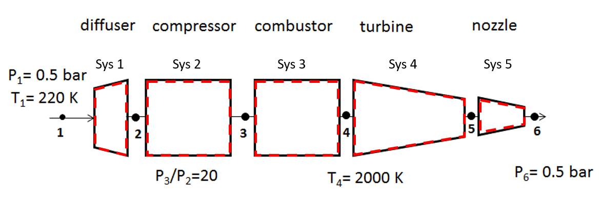
The engine is attached to an aircraft moving at 260 m/s through air at 220 K and 0.5 bar. The compressor pressure ratio is 20:1 and the combustor exit temperature is 2000 K. Assume the diffuser exit velocity (State 2) is small compared to the inlet (State 1) and the nozzle inlet velocity (State 5) is small compared to its exit (State 6).
#Given Inputs:

V_1 = 260          # aircraft velocity [m/s]
P_1 = 50           # pressure at state 1 [kPa]
T_1 = 220          # temperature at state 1 [K]
T_4 = 2000         # temperature at state 4 [K]
P_6 = 50           # pressure at state 6 [kPa]
r_comp = 20        # compressor pressure ratio [-]
R = 0.287          # air gas constant [KJ/kg-K]
Find:
Part (a): air pressure (kPa) and temperature (K) the diffuser exit
Part (b): air pressure (kPa) and temperature (K) the compressor exit
Part (c): specific compressor work (kJ/kg)
Part (d): specific heat transfer in the combustor (kJ/kg)
Part (e): turbine exit temperature (K) and pressure (kPa)
Part (f): nozzle exit velocity
System Diagram:
Each component is analyzed as a control volume as shown on the diagrams (sys 1-5).
Assumptions:
Following are the common assumptions for all the control volumes:
1) Open system,
2) Steady state, steady flow (SSSF),
3) Ideal gas for air,
4) Negligible changes in potential energy,
For different components, there are additional assumptions needed:
5) Reversible and adiabatic processes (isentropic) for the diffuser, compressor, nozzle and turbine,
6) No pressure drop across the combustor,
7) Negligible changes in kinetic energy for the compressor, combustor, and turbine
8) The compressor input work is equal to the turbine work output (back-work ratio of 1),
9) Diffuser exit velocity (State 2) is small compared to the inlet (State 1),
10) Nozzle inlet velocity (State 5) is small compared to its exit (State 6).
Basic Equations:
$$Pv = RT$$$$\dfrac{dm}{dt}=\Sigma \dot m_{in}-\Sigma \dot m_{out}$$$$\dfrac{dE}{dt} = \dot Q- \dot W + \displaystyle\sum_{in} \dot m_{in} (h+ke+pe)_{in}-\displaystyle\sum_{out} \dot m_{out}(h+ke+pe)_{out}$$$$\bigg (\dfrac{P_2}{P_1}\bigg )_s=\bigg (\dfrac{P_{r2}}{P_{r1}} \bigg)_s$$# State 1:
P_r1 = 0.4690 # relative pressure at state 1 from the ideal gas table
u_1 = 156.8 # internal energy of air at state 1 from the ideal gas table [kJ/kg]
h_1 = 220.0 # enthalpy of air at state 1 from the ideal gas table [kJ/kg]
State 2:
Mass and energy balances are applied to the diffuser (state 1 to 2) to determine the exit enthalpy using the assumptions of steady steady, steady flow ($dm/dt=0, dE/dt=0$), adiabatic, no work, negligible changes in potential energy, and negligible exit kinetic energy
$$ h_2 = h_1 + \dfrac{V_1^2}{2} $$# State 2:
h_2 = h_1 + V_1*V_1/2/1000 # enthalpy of air at state 2, pay attention to the unit [kJ/kg]
print('h_2 = ',round(h_2,4),'kJ\kg')
The exit enthalpy is used along with the ideal gas table to determine the exit temperature and relative pressure. Since the process is isentropic, the exit pressure can be found from the following isentropic relation for an ideal gas.
$$\bigg (\dfrac{P_2}{P_1}\bigg )_s=\bigg (\dfrac{P_{r2}}{P_{r1}} \bigg)_s$$$$ P_2=P_1\dfrac{P_{r2}}{P_{r1}}$$# State 2 properties can be found using the ideal gas table:
T_2 = 253.8 # temperature at the state 2 from the ideal gas table at h_2, using interpolation [K]
P_r2 = 0.7738 # relative pressure at state 2 from the ideal gas table
P_2 = P_1*P_r2/P_r1 # diffuser exit pressure [kPa]
print('P_2',round(P_2,2),'kPa')
print('T_2',round(T_2,2),'K')
Part(b): air pressure (kPa) and temperature (K) at the compressor exit
State 3:
The compressor pressure ratio and the inlet pressure are used to determine the compressor exit pressure at state 3. Since the process is also isentropic, the relative pressure can be calculated and used to find the exit temperature and enthalpy at state 3 from the ideal gas table.
$$\dfrac{P_3}{P_2}=r_{comp}$$$$P_3=P_2r_{comp}$$$$\bigg (\dfrac{P_3}{P_2}\bigg )_s=\bigg (\dfrac{P_{r3}}{P_{r2}} \bigg)_s$$$$P_{r3}=P_{r2}r_{comp}$$# State 3 properties can be found using the ideal gas table:
P_3 = P_2*r_comp # pressure at state 3 [kPa]
P_r3 = P_r2*r_comp # relative pressure at state 3
print('P_3 = ',round(P_3,2),'kPa')
print('P_r3 = ',round(P_r3,2))
T_3 = 591.7 # temperature at state 3 from the ideal gas table, using interpolation [K]
h_3 = 598.5 # enthalpy of air at state 3 from the ideal gas table [kJ/kg]
print('T_3 = ',round(T_3,2),'K')
Part(c): specific compressor work (kJ/kg)
Since the compressor is adiabatic with no heat transfer and SSSF, mass and energy balances lead to:
$$w_{23} = h_2 - h_3 $$w_23 = h_2 - h_3 # specific compressor work [kJ/kg]
print('w_23 = ',round(w_23,2),'kJ/kg')
Part(d): specific heat transfer in the combustor (kJ/kg)
State 4:
The combustor outlet (state 4) temperature is given and there is no pressure drop through the combustor. Since there is no work and the assumptions include steady state, steady flow ($dm/dt=0, dE/dt=0$) and negligible changes in $ke$ and $pe$, then mass and energy balances lead to
$$q_{34} = h_4 - h_3 $$# State 4:
P_4 = P_3 # pressure at the state 4 [kPa]
u_4 = 1678 # internal energy of air at state 4 from the ideal gas table [kJ/kg]
h_4 = 2252 # enthalpy of air at state 4 from the ideal gas table [kJ/kg]
P_r4 = 2068 # relative pressure at state 4
q_34 = h_4 - h_3 # specific heat transfer in combustor [kJ/kg]
print('q_34',round(q_34,2),'kJ/kg')
Part(e): turbine exit temperature (K) and pressure (kPa)
State 5:
Assuming SSSF, negiligible changes in kinetic and potential energy, and adiabatic, then the work output from the turbine per unit mass of flow is
$$w_{45} = h_4 - h_5$$Since the back-work ratio is 1, the work output from the turbine is equal to the compressor work input or $w_{45} = -w_{23}$. Thus, the turbine exit enthalpy can be determined as
$$h_5 = h_4 + w_{23}$$# State 5:
w_45 = -w_23 # turbine specific work [kJ/kg]
h_5 = h_4 - w_45 # enthalpy of air at state 5 [kJ/kg]
print('h_5 =',round(h_5,2),'kJ/kg')
The exit turbine enthalpy can then be used to calculate the temperature of the air along with the relative pressure using the ideal gas tables. Since the process from 4 to 5 is isentropic, then the exit pressure can be determined from the inlet pressure and relative pressures using the isentropic relation for an ideal gas.
$$\bigg (\dfrac{P_5}{P_4}\bigg )_s=\bigg (\dfrac{P_{r5}}{P_{r4}} \bigg)_s$$$$P_{5}=P_{4}\dfrac{P_{r5}}{P_{r4}}$$# State 5:
T_5 = 1722.0 # temperature at state 5 from ideal gas table, interpolation uesed [K]
P_r5 = 1084.9 # relative pressure at state 5
P_5 = P_4*P_r5/P_r4 # pressure at the state 5 [kPa]
print('T_5 = ',round(T_5,1),'K')
print('P_5 = ',round(P_5,1),'kPa')
Part(f): nozzle exit velocity (m/s)
State 6:
The process 5-6 across the nozzle is also isentropic and the pressure at state 6 is known. The relative pressure at state 6 can then be calculated to find the temperature and other air properties.
$$\bigg (\dfrac{P_6}{P_5}\bigg )_s=\bigg (\dfrac{P_{r6}}{P_{r5}} \bigg)_s$$$$P_{r6}=P_{r5}\dfrac{P_{6}}{P_{5}}$$# State 6:
P_r6 = P_r5*P_6/P_5 # relative pressure at state 6
print('P_r6 = ',round(P_r6,2))
# State 6:
T_6 = 858.5           # temperature at state 6 from ideal gas table, interpolation uesed [K]
h_6 = 886.5           # enthalpy of air at state 6 from ideal gas table [kJ/kg]
Finally, the nozzle exit air velocity is determined from mass and energy balances on the nozzle under the assumptions of SSSF, no work, no heat transfer, negligible changes in potential energy, and negligible inlet kinetic energy.
$$ \dfrac{V_6^2}{2} = h_5 - h_6 $$# Exit velocity
import math
V_6 = math.sqrt(2*(h_5-h_6)*1000) # nozzle exit velocity [m/s]. Pay attention to the unit conversion!
print('V_6 = ',round(V_6,2),'m/s')