ME 200 – Thermodynamics I – Spring 2020
Homework 39: Diesel Cycles
Part (a): Thermal Efficiency
Part (b): Mean effective pressure
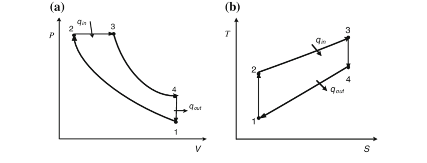
Part (c): P-v and T-s diagram
Given:
An ideal Diesel engine has a compression ratio of 20 and uses air as the working fluid. The state of air at the beginning of the compression process is 95 kPa and 295 K. The maximum temperature in the cycle is 2200 K.
#Given Inputs:
P_1 = 95           # pressure at the begining of the compression process (state 1) [kPa]
T_1 = 295          # temperature at the begining of the compression process (state 1) [K]
T_3 = 2200         # maximum temperature in the cycle [K]
r = 20             # compression ratio of 20 [-]
R = 0.287          # air gas constant [KJ/kgK]
Find:
Part (a): Thermal efficiency
Part (b): Mean effective pressure
Part (c): P-v and T-s diagram
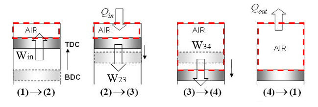
System Diagram:
The system diagram shows all the processes for the diesel cycle with states labeled. We select the air in the piston-cylinder assembly as the closed system.
Assumptions:
1) closed system,
2) all the processes are internally reversible,
3) adiabatic compression (1-2),
4) adiabatic for the second expansion process (3-4),
5) negligible changes in kinetic and potential energy,
6) ideal gas for air
Basic Equations:
$$\dfrac{dE}{dt} = \dot Q- \dot W + \displaystyle\sum_{in} \dot m_{in} (h+ke+pe)_{in}-\displaystyle\sum_{out} \dot m_{out}(h+ke+pe)_{out}$$$$Pv = RT$$$$ W = \int P dv $$$$\bigg (\dfrac{v_2}{v_1}\bigg )_s=\bigg (\dfrac{v_{r2}}{v_{r1}} \bigg)_s$$$$\eta _{th} = \dfrac{W_{net,out}}{Q_{in}}$$$$mep = \dfrac{w_{net,out}}{v_{max}-v_{min}}$$Solution:
Part (a): Thermal Efficiency
States 1 and 2:
The analysis begins by determining the properties at each state point of the cycle. The pressure and temperature at state 1 are known and the ideal gas law can be used to determine the specific volume. The compression process from state 1 to 2 is isentropic (adibatic + internaly reversible), so that the relative volume at state 2 can be determined using the isentropic relation for an ideal gas along with the compression ratio. This can then be used to find the temperature and internal energy at state 2 using interpolation in the ideal gas table. The pressure at state 2 can be found using ideal gas law.
$$v_1 = \dfrac{RT_1}{P_1}$$$$\dfrac{v_2}{v_1}=r=\dfrac{v_{r2}}{v_{r1}}$$$$v_{r2}=\dfrac{v_{r1}}{r}$$$$P_2 = P_1\dfrac{T_2}{T_1}\dfrac{v_1}{v_2}$$# State 1:
v_1 = R*T_1/P_1 # specific volume at state 1 [m^3/kg]
v_r1 = 647.9 # relative volume at state 1 from the ideal gas table
u_1 = 210.5 # internal energy of air at state 1 from the ideal gas table [kJ/kg]
h_1 = 295.1 # enthalpy of air at state 1 find in the ideal gas table [kJ/kg]
print('v_1 = ',round(v_1,4),'m^3\kg')
# State 2:
v_2 = v_1/r # specific volume at state 2 [m^3/kg]
v_r2 = v_r1/r # relative volume at state 2
T_2 = 918.0 # temperature at state 2 from ideal gas table, interpolation used [K]
u_2 = 689.6 # internal energy of air at state 2 from ideal gas table, interpolation used [kJ/kg]
h_2 = 953.14 # enthalpy of air at state 2 from ideal gas table [kJ/kg]
P_2 = P_1*T_2*v_1/T_1/v_2 # pressure at state 2 [kPa]
print('v_2 = ',round(v_2,4),'m^3\kg')
print('v_r2 = ',round(v_r2,2))
print('P_2 = ',round(P_2,1),'kPa')
State 3:
For the Diesel cycle, the heat addition process from 2 to 3 occurs at constant pressure. This is meant to represent a "slow" combustion process and occurs in combination with a portion of the work expansion stroke. Since the pressure is constant and temperature at state 3 is given (2200 K), then the specific volume at state 3 can calculated from the ideal gas law.
$$P_2 = P_3$$$$\dfrac{RT_2}{v_2} = \dfrac{RT_3}{v_3}$$$$v_3 = \dfrac{v_2T_3}{T_2}$$# State 3:
P_3 = P_2 # pressure at state 3 [kPa]
v_3 = v_2*T_3/T_2 # specific volume at state 3 [m^3/kg]
v_r3 = 2.012 # relative volume at state 3 from the ideal gas table
u_3 = 1873 # internal energy of air at state 3 from the ideal gas table [kJ/kg]
h_3 = 2503 # enthalpy of air at state 3 from the ideal gas table [kJ/kg]
print('v_3 = ',round(v_3,4),'m^3\kg')
print('P_3 = ',round(P_3,1),'kPa')
State 4:
The process 3 to 4 is an isentropic expansion process, but only occurs over a portion of the overall expansion stroke. The isentropic relation for an ideal gas can be used along with known specific volumes to determine the relative volume at state 4.
$$v_{r4} = v_{r3}\dfrac{v_4}{v_3}$$Note that $v_4 = v_1$. The relative volume at state 4 can then be used to determine the temperature and internal energy at state 4 using the ideal gas table with interpolation. The pressure at state 4 is calculated using the ideal law either and conservation of mass applied to either process 3 to 4 (T, P, and v changing) or 4 to 1 (T and P changing, v is constant). Both give the same result.
# State 4:
v_4 = v_1                                # specific volume at state 4 [m^3/kg]
v_r4 = v_r3*v_4/v_3                      # relative volume at state 4
T_4 = 1143.5                             # temperature at state 4 from the ideal gas table, interpolation used [K]
u_4 = 883.8                              # internal energy of air at state 4 from the ideal gas table, interpolation used [kJ/kg]
h_4 = 1212.04                            # enthalpy of air at state 4 from the ideal gas table [kJ/kg]
P_4 = P_3*T_4*v_3/T_3/v_4                # pressure at state 4 [kPa]
P_4_alt = P_1*T_4/T_1
print('v_4 = ',round(v_4,4),'m^3/kg')
print('v_r4 = ',round(v_r4,3))
print('P_4 = ',round(P_4,1),'kPa')
print('P_4_alt = ',round(P_4_alt,1),'kPa')
With all the states known, the following state table can be used as a summary for the cycle.
| State | T (K) | P (kPa) | u (kJ/kg) | h {kJ/kg) | v (m^3/kg) | v_r |
|---|---|---|---|---|---|---|
| 1 | 295 | 95 | 210.5 | 295.1 | 0.8912 | 647.9 |
| 2 | 918.0 | 5912.5 | 689.6 | 953.14 | 0.0446 | 32.39 |
| 3 | 2200 | 5912.5 | 1873 | 2503 | 0.1068 | 2.012 |
| 4 | 1143.5 | 368.2 | 883.8 | 1212.04 | 0.8912 | 16.791 |
Process analysis for heat addition and rejection:
Heat addition in the Diesel cycle occurs at constant pressure in combination with work output for the process 2 to 3. The boundary work per unit mass for this process is
$$ w_{23} = \int P dv = P_2(v_3 - v_2) $$The heat transfer can then be determined using a first law energy balance for a closed system with negligible changes in kinetic and potential energy.
$$ u_3 - u_2 = q_{23} - w_{23} $$Solving for heat transfer and using $P_3 = P_2$:
$$ q_{23} = (u_3 - u_2) + P_2(v_3 - v_2) = (u_3 + P_3v_3) - (u_2 + P_2v_2) = h_3 - h_2 $$Enthalpy terms show up for this closed system only because it is a constant pressure process.
The heat rejection process from 4 to 1 in the Diesel cycle is the same as the Otto cycle with constant volume. Simplifying the first law using the assumptions of negligible changes in kinetic and potential energy and constant volume (no work) leads to:
$$ q_{41} = u_1 - u_4 $$Then, the net work for the cycle can be determined as the net heat addition to the cycle:
$$ w_{net} = q_{23} + q_{41} = (h_3 - h_2) - (u_4 - u_1) $$q_23 = h_3 - h_2 # heat addition to the cycle [kJ/kg]
q_41 = u_1 - u_4 # heat rejection from the cycle [kJ/kg]
w_net = q_23 + q_41 # net work output of the cycle [kJ/kg]
print('q_23 = ',round(q_23,3),'kJ/kg')
print('q_41 = ',round(q_41,3),'kJ/kg')
print('w_net = ',round(w_net,3),'kJ/kg')
Using the nomenclature of this problem, the thermal efficiency of the cycle is
$$\eta _{th} = \dfrac{w_{net}}{q_{23}}$$eta_th = w_net/q_23
print('q_in = ',round(q_23,3),'kJ/kg')
print('eta_th = ',round(eta_th,3))
Part(b): Mean effective pressure
The mean effective pressure (mep) of the cycle is the ratio of the net work output of the cycle to the displacement volume of the cylinder during the expansion stroke. This reduces to
$$mep = \dfrac{W_{net}}{V_{max}-V_{min}}$$where
$$V_{max} - V_{min} = V_1 - V_2 = m(v_1 - v_2)$$Therefore,
$$mep = \dfrac{w_{net}}{v_1-v_2}$$mep = w_net/(v_1 - v_2)
print('mep = ',round(mep,2),'kPa')
Part(c): P-v and T-s diagrams