ME 200 – Thermodynamics I – Spring 2020
Homework 29: Entropy Generation for Steady-State Open Systems and Cycles
Part (i): Throttling Valve and Heat Exchanger
Part (ii): Compressor
Part (iii): Entire Air Conditioner
#Given Inputs:
P_1 = 1800          # entering pressure of propane to the valve [kPa]
x_1 = 0.0           # entering quality of propane to the valve
T_v = 4             # exiting temperature of propane from the valve [°C]
P_v = 535.1         # exit pressure of propane from the valve [kPa]
x_v = 0.363         # exit quality of propane from the valve
m_dot_a =  1.0      # mass flow of the air through the heat exchanger [kg/s]
m_dot_p =  0.0425   # mass flow of the propane through the heat exchanger [kg/s]
T_a_1 = 20          # inlet air temperature at the heat exchanger [C]
T_a_2 = 10          # outlet air temperature at the heat exchanger [C]
T_p_2 = 4           # outlet propane temperature from the heat exchanger [C]
P_2 = P_v           # outlet propane pressure from the heat exchanger [kPa]
x_p_2 = 1.0         # outlet propane quality from the heat exchanger
Find:
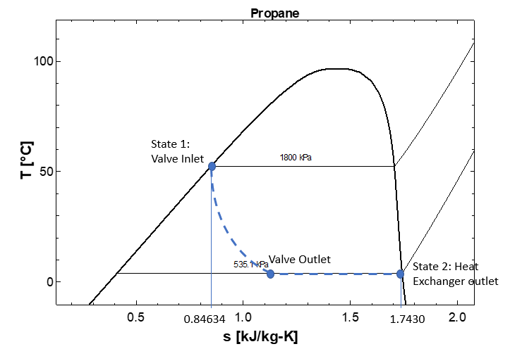
Determine the total rate of entropy generation in kW/K. Sketch a T-s diagram for the propane.
System Diagram:
The system is the throttling valve and heat exchanger. The problem can be done with a single system.
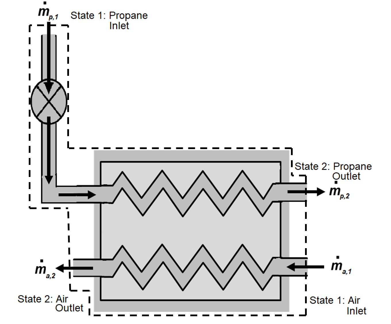
Assumptions:
1) open system, 2) steady state, steady flow (SSSF) 3) adiabatic (no heat transfer to the surroundings), 4) air is an ideal gas, 5) no pressure drop for air or propane in the heat exchanger
Basic Equations:
$$\dfrac{dm}{dt}=\Sigma \dot m_{in}-\Sigma \dot m_{out}$$$$\dfrac{dS}{dt} = \displaystyle\sum_{j} \dfrac{\dot Q_j}{T_{j,boundary}}+ \displaystyle\sum_{in} \dot m_{in} s_{in}-\displaystyle\sum_{out} \dot m_{out}s_{out}+\dot \sigma _{generation}$$$$z_{mix}=xz_g+(1-x)z_f$$$$s_2-s_1=s_2^o-s_1^o-R \cdot ln \Bigg(\dfrac{P_2}{P_1}\Bigg)$$Solution:
Mass balances are applied to each of the two single-inlet, single-outlet flow streams with the assumption of steady flow ($dm/dt=0$).
$$\dot m_{a,2} = \dot m_{a,1} = \dot m_{a}$$$$\dot m_{p,2}=\dot m_{p,1} = \dot m_p$$An entropy balance is applied to the entire system consisting of the valve, heat exchanger, and two flow streams with the assumption of SSSF ($dS/dt=0$). Also, the overall system is adiabatic ($\dot Q=0$) since the heat transfer between the air and refrigerant is internal to the system.The simplified entropy balance becomes
$$0 = 0 + \dot m_{a,1}s_{a,1}+\dot m_{p,1}s_{p,1}- \dot m_{a,2}s_{a,2} - \dot m_{p,2}s_{p,2}+ \dot\sigma _{generation}$$or
$$\dot\sigma _{generation} = \dot m_{p}(s_{p,2}-s_{p,1}) + \dot m_{a}(s_{a,2}-s_{a,1})$$The change in entropy of the air treated as an ideal gas from the basic equations is
$$s_2-s_1=s_2^o-s_1^o-R \cdot ln\Bigg(\dfrac{P_2}{P_1}\Bigg)$$Furthermore, the problem statement states that the heat exchanger can be assumed to have no pressure drop, thus the entropy balance simplifies to the following.
$$\dot \sigma _{generation} = \dot m_{a}(s_{a,2}^o-s_{a,1}^o)+ \dot m_{p}(s_{p,2}-s_{p,1})$$The propane inlet entropy ($s_{p,1}$) can be determined from the specified inlet conditions of saturated liquid propane at 18 bar.
$$s_{p,1}=0.84634 kJ/kgK$$The exit state of the propane is defined as saturated vapor at 4°C and thus can be taken from the SLVM tables.
$$s_{p,2}=1.7430 kJ/kgK$$We probably could assume constant specific heat for the air since the temperature change is small. However, we will use the ideal gas tables to look up values for $s_{a,2}^o$ and $s_{a,1}^o$ at $T_{a,1} = 20°C$ and $T_{a,2} = 10°C$.
$$s_{a,1}^o = 1.680kJ/kgK, s_{a,2}^o = 1.644kJ/kgK$$The total rate of entropy generation can now be determined.
s_a1_o = 1.680              # temperature portion entropy evaluation for air at state 1 [kJ/kg-K]
s_a2_o = 1.644              # temperature portion entropy evaluation for air at state 2 [kJ/kg-K]
s_p1 = 0.84634              # entropy of propane at state 1 [kJ/kg-K]
s_p2 = 1.7430               # entropy of propane at state 2 [kJ/kg-K]

sigma_dot_gen = m_dot_a*(s_a2_o-s_a1_o)+m_dot_p*(s_p2-s_p1)
print('sigma_dot_gen = ',round(sigma_dot_gen,5),'kW/K')
#Given Inputs:
T_1 = 4                 # propane inlet temperature [C]
x_1 = 1                 # propane inlet quality
P_2 = 1800              # propane exit pressure [kPa]
T_2 = 50                # propane exit temperature [C]
W_dot_c = -2.99         # compressor work [kW]
Q_dot_c = 0.1*W_dot_c   # compressor heat transfer [kW]
T_boundary = 42+273.15  # boundary temperature [K]
Find:
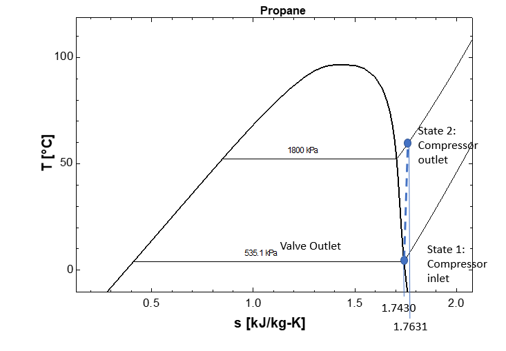
Determine the compressor total entropy generation. Depict the process on a T-s diagram.
What is the exit temperature in the case that the compressor is assumed to be adiabatic and internally reversible? Depict this process on a T-s diagram.
System Diagram:
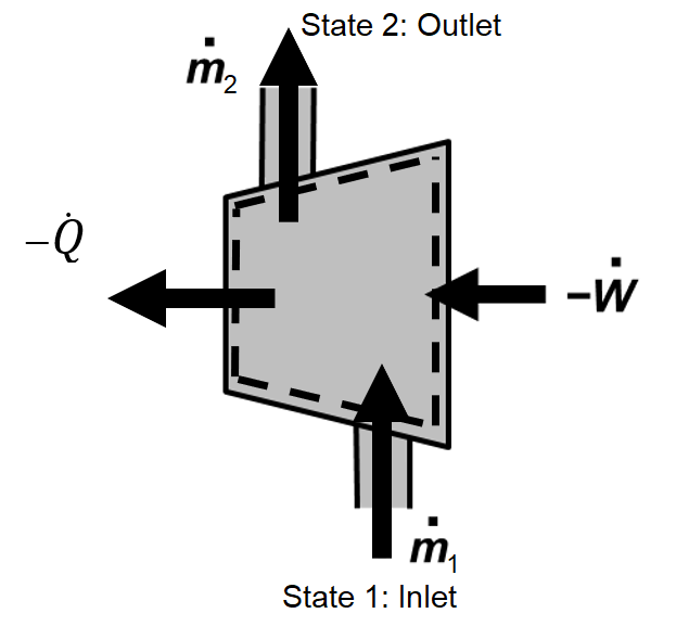
Assumptions:
1) open system, 2) steady state, steady flow (SSSF)
Basic Equation:
$$\dfrac{dm}{dt}=\Sigma \dot m_{in}-\Sigma \dot m_{out}$$$$\dfrac{dS}{dt} = \displaystyle\sum_{j} \dfrac{\dot Q_j}{T_{j,boundary}}+ \displaystyle\sum_{in} \dot m_{in} s_{in}-\displaystyle\sum_{out} \dot m_{out}s_{out}+\dot \sigma _{generation}$$Solution:
For the given nomenclature of this problem, mass and entropy balances can be written for this single inlet, single outlet control volume as
$$\dfrac{dm}{dt} = \dot m_1 - \dot m_2$$$$\dfrac{dS}{dt} = \dfrac{\dot Q}{T_{boundary}}+ \dot m_{1}s_{1} - \dot m_{2}s_{2}+\dot \sigma _{generation}$$For the assumptions of SSSF ($dm/dt=0, dS/dt=0$) these can be rewritten as
$$\dot m_2 = \dot m_1 = \dot m_p$$ $$\dot \sigma _{generation} = \dot m_{p} (s_{2}-s_{1})-\dfrac{\dot Q}{T_{boundary}}$$The value for $s_1$ is taken from the SLVM table at 4°C and a quality of 1 (saturated vapor).
$$s_1=1.7430kJ/kgK$$The value for $s_2$ is taken from the SHV table at 50°C and 18 bar.
$$s_2=1.7631kJ/kgK$$The value for heat transfer comes from HW 16 (iii).
$$\dot Q_c=0.1\dot W_c$$s_1 = 1.7430 # entropy of propane at state 1 [kJ/kg-K]
s_2 = 1.7631 # entropy of propane at state 2 [kJ/kg-K]
sigma_dot_gen = m_dot_p*(s_2-s_1)-Q_dot_c/T_boundary
print('sigma_dot_gen = ','%.5f'%sigma_dot_gen,'kW/K')
Now consider the case where the compressor is adiabatic and internally reversible along with SSSF ($\dot Q_c=0$, $\dot \sigma_{generation} = 0$, and $dS/dt=0$.
$$\dfrac{dS}{dt} = \dfrac{\dot Q}{T_{boundary}}+ \dot m_{p} (s_{1}-s_{2})+\dot \sigma _{generation}$$such that
$$0 = 0 + \dot m_{p} (s_{1}-s_{2})+0$$and
$$s_2=s_1=1.7430kJ/kgK$$Thus, a reversible and adiabatic SSSF process for a single-inlet, single-outlet open system is isentropic. Since the exit pressure is known, then the superheated vapor table and the exit pressure of 18 bar can be used to degtermine the exit temperature of the compressor via interpolation.
$$T_2=T_a+(s_2-s_a)\dfrac{T_b-T_a}{s_b-s_a}=52.27+(1.7430-1.7051)\dfrac{60-52.27}{1.7631-1.7051}$$$$T_2=57.32°C$$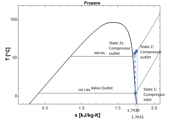
#Given Inputs:
T_C = 20 + 273.15   # temperature of the room [K]
T_H = 42 + 273.15   # temperature of the ambient envoirment [K]
Q_dot_C = 10        # heat transfer rate from the air in the room to the air conditioner [kW]
Find:
Determine the total entropy generation rate.
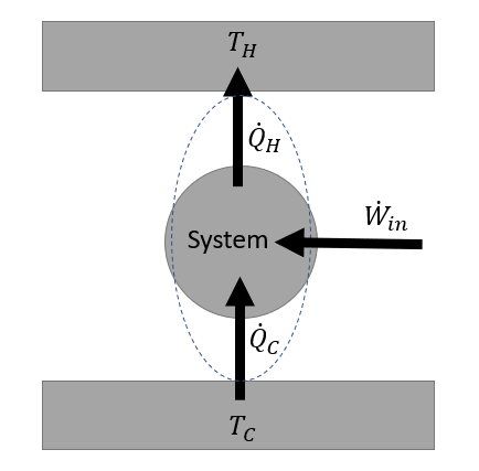
System Diagram:
The system is the entire cycle. The boundary of the system should "touch" the two reservoirs in order to capture all of the heat tranfer irreversibilities.
Assumptions:
1) closed system, 2) steady state, steady flow (SSSF)
Basic Equation:
$$\dfrac{dE}{dt} = \dot Q- \dot W + \displaystyle\sum_{in} \dot m_{in} (h+ke+pe)_{in}-\displaystyle\sum_{out} \dot m_{out}(h+ke+pe)_{out}$$$$\dfrac{dS}{dt} = \displaystyle\sum_{j} \dfrac{\dot Q_j}{T_{j,boundary}}+ \displaystyle\sum_{in} \dot m_{in} s_{in}-\displaystyle\sum_{out} \dot m_{out}s_{out}+\dot\sigma _{generation}$$Solution:
For the given nomenclature and sign convention for this steady-state closed cycle ($dE/dt=0, dS/dt=0$), energy and entropy balances can be written as
$$0 = \dot Q_C - \dot Q_H + \dot W_{in} $$$$0 = \dfrac{\dot Q_C}{T_C} - \dfrac{\dot Q_H}{T_H} + \dot \sigma _{generation}$$where the typical refrigeration cycle convention is employed (positive heat transfer from low temperature source, positive heat transfer to high temperature sink, and positive power input). It should be noted that the heat rejection to the high temperature sink is a result of both heat transfer from condenser and heat loss from the compressor. Since both occur to the same surrounding temperature, these can be treated as a single heat transfer term in the overall energy and entropy balances.
Then, the entropy generation is determined as
$$\dot \sigma_{generation} = \dfrac{\dot Q_H}{T_{H}} - \dfrac{\dot Q_C}{T_{C}}$$where the value for $\dot Q_H$ is
$$\dot Q_H = \dot Q_C + \dot W_{in} $$W_dot_in = 2.99 # compressor power input [kW]
Q_dot_H = Q_dot_C + W_dot_in # total heat transfer to ambient [kW]
sigma_dot_gen = Q_dot_H/T_H - Q_dot_C/T_C # total entropy generation rate [kW/K]
print('Q_dot_H = ',round(Q_dot_H,3),'kW')
print('sigma_dot_gen = ',round(sigma_dot_gen,6),'kW/K')