ME 200 – Thermodynamics I – Spring 2020
Homework 16: More Open System Energy Balances
Part (i): Throttling Valve
Part (ii): Heat Exchanger
Part (iii): Compressor
#Given Input:
P_1 = 1800          # entering pressure of propane [kPa]
x_1 = 0.0           # entering quality of propane
T_2 = 4             # exiting temperature propane [°C]
Find:
Determine the exit pressure and quality. Sketch a P-v diagram.
Assumptions:
1) open system, 2) steady state, steady flow (SSSF) 3) no work 4) negligible changes in potential and kinetic energy, 5) adiabatic (no heat transfer)
Basic Equations:
$$\dfrac{dm}{dt}=\Sigma \dot m_{in}-\Sigma \dot m_{out}$$$$\dfrac{dE}{dt} = \dot Q- \dot W + \displaystyle\sum_{in} \dot m_{in} (h+ke+pe)_{in}-\displaystyle\sum_{out} \dot m_{out}(h+ke+pe)_{out}$$$$z_{mix}=xz_g+(1-x)z_f$$Solution:
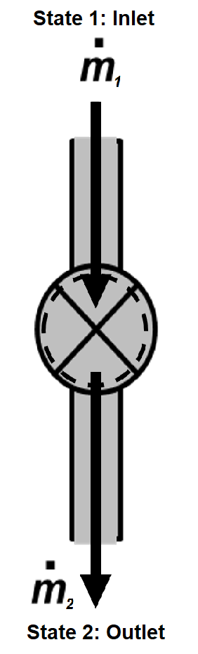
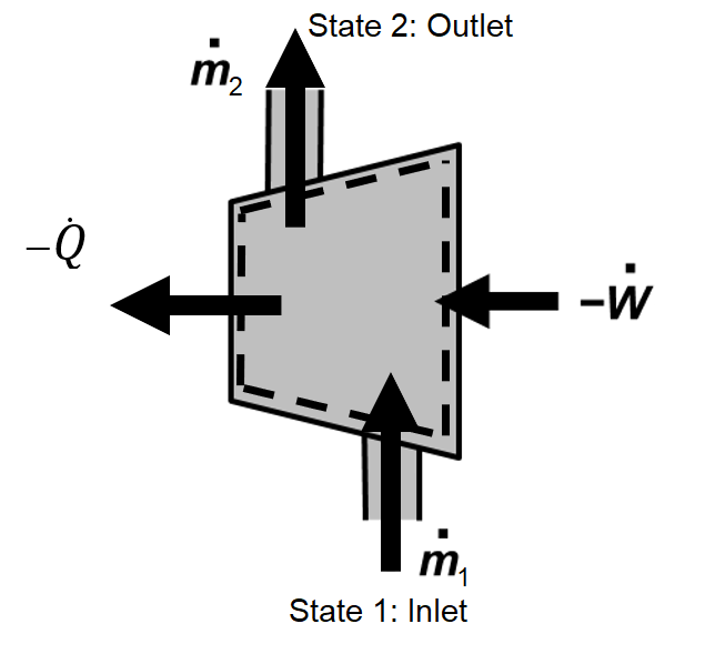
For the given nomenclature of this problem, conservation of mass and energy can be written for this single inlet, single outlet control volume as
$$\dfrac{dm}{dt} = \dot m_1 - \dot m_2$$$$\dfrac{dE}{dt} = \dot Q- \dot W + \dot m_1(h+ke+pe)_1 - \dot m_2(h+ke+pe)_2$$For the assumptions of SSSF ($dm/dt=0, dE/dt=0$), no work ($\dot W=0$), adiabatic ($\dot Q=0$), and negligible changes in potential energy ($pe_2 = pe_1$) and kinetic energy ($ke_2 = ke_1$), these can be rewritten as
$$\dot m_2 = \dot m_1 = \dot m$$ $$0 = \dot m(h_1-h_2)$$Therefore,
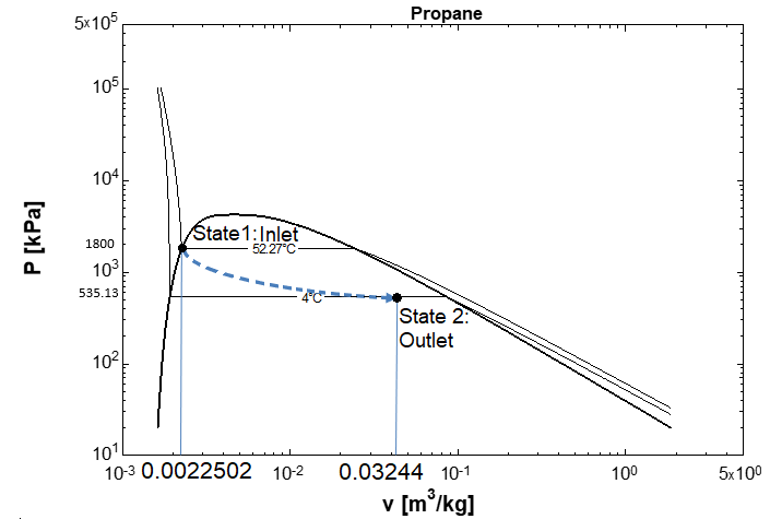
$$h_2=h_1$$This is a typical result for a throttling valve where the inlet and outlet enthalpies are approximately the same. The inlet properties ($h_1, T_1, v_1$) can be determined from the specified inlet conditions of saturated liquid propane at 18 bar.
$$h_1=239.41 kJ/kg, T_1=52.272°C, v_1=0.0022502 m^3/kg$$The exit state is defined since $h_2=h_1$ and $T_2=4°C$. The exit state is a two-phase mixxture and quality can be determined from the known value of h_2 and saturation properties at °4C.
$$x_2 = \dfrac{h_2-h_f}{h_g-h_f}$$We can also determine the exit specific volume for plotting a P-v diagram.
$$v_2=x_2v_g+(1-x_2)v_f$$h_1 = 239.41 # enthalpy of propane entering the valve at 18 bar [kJ/kg]
T_1 = 52.272 # temperature of propane entering the valve [°C]
v_1 = 0.0022502 # specific volume of propane entering the valve [m^3/kg]
h_2 = h_1
h_f = 105.32 # enthalpy of saturated liquid propane at 4°C [kJ/kg]
h_g = 474.73 # enthalpy of saturated vapor propane at 4°C [kJ/kg]
x_2 = (h_2-h_f)/(h_g-h_f) # exit quality of propane
P_2 = 535.13 # saturation pressure of SLVM propane at 4°C [kPa]
v_2 = 0.03244 # specific volume of propane leaving the valve [m^3/kg]
print('P_2 = ',round(P_2,1),'kPa')
print('x_2 = ',round(x_2,3))
Part(ii): Heat Exchanger
Given
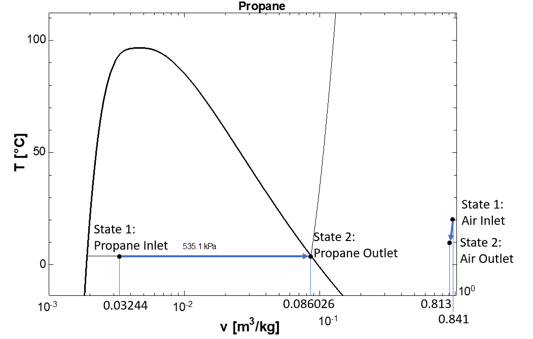
A heat exchanger with a heat transfer rate of 10 kW from the air to the propane has an inlet air temperature of 20°C, an outlet air temperature of 10°C, a propane inlet temperature of 4°C and quality 0f 0.363, and a propane outlet temperature of 4°C with saturated vapor as the state.
#Given Input:
Q_dot_p = 10       # heat transfer rate from air to propane [kW]
T_a_1 = 20         # inlet air temperature [C]
T_a_2 = 10         # outlet air temperature [C]
T_p_1 = 4          # inlet propane temperature [C]
T_p_2 = T_p_1      # outlet propane temperature
x_p_1 = 0.363      # inlet propane quality from part (i)
x_p_2 = 1.0        # outlet propane quality
Find:
Determine the air mass flow rate in kg/s, the propane mass flow rate in kg/s, and sketch a Tv diagram.
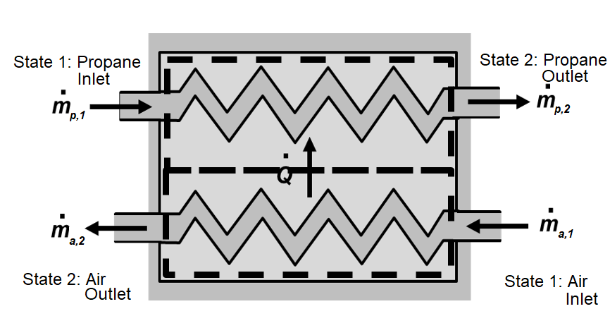
System Diagram:
Two different systems are employed: 1) air within the heat exchanger and 2) propane within the heat exchanger.
Assumptions:
1) open system, 2) steady state, steady flow (SSSF) 3) negligible changes in kinetic and potential energy, 4) no work, 5) air is an ideal gas.
Basic Equation:
$$\dfrac{dm}{dt}=\Sigma \dot m_{in}-\Sigma \dot m_{out}$$$$\dfrac{dE}{dt} = \dot Q- \dot W + \displaystyle\sum_{in} \dot m_{in} (h+ke+pe)_{in}-\displaystyle\sum_{out} \dot m_{out}(h+ke+pe)_{out}$$$$z_{mix}=xz_g+(1-x)z_f$$$$Pv=RT$$Solution:
Mass and energy balances are applied to each of the two single-inlet, single-outlet flow streams with the assumptions of SSSF ($dm/dt=0, dE/dt=0$), no work ($\dot W=0$), and negligible changes in potential energy ($pe_2 = pe_1$) and kinetic energy ($ke_2 = ke_1$). The simplified conservation equations become
$$\dot m_{a,2} = \dot m_{a,1} = \dot m_{a}$$$$\dot m_{p,2}=\dot m_{p,1} = \dot m_p$$$$0=\dot Q_a + \dot m_a(h_{a,1}-h_{a,2})$$$$0=\dot Q_p +\dot m_p(h_{p,1}-h_{p,2})$$The heat transfer rate to the propane ($\dot Q_p$) is $10 kW$ and is equal but opposite in sign to the heat transfer rate for the air.
$$\dot Q_a = -\dot Q = -10 kW$$Then, the required air and propane flow rates can be determined from the known heat transfer rates along with enthalpy changes according to
$$\dot m_a = \dfrac{\dot Q_a}{h_{a,2}-h_{a,1}}$$$$\dot m_p = \dfrac{\dot Q_p}{h_{p,2}-h_{p,1}}$$We could reasonably assume constant specific heat for the air because the temperature change is small. However, it is also relatively easy to use the ideal gas tables to look up values for $h_{2,a}$ and $h_{1,a}$ at $T_{a,1} = 20°C$ and $T_{a,2} = 10°C$.
$$h_{a,1} = 293.25kJ/kg, h_{a,2} = 283.25kJ/kg$$Saturation properties are used to determine the propane enthalpies. The entering propane has a temperature of 4°C and a quality of 0.363. The mixture enthalpy is then
$$h_{p,2} = x_{p,2}h_g+(1-x_{p,2})h_f$$The enthalpy of the exiting propane is evaluated as the saturated vapor value at 4°C.
h_a_1 = 293.25          # enthalpy of air entering the heat exchanger at 20°C [kJ/kg]
h_a_2 = 283.25          # enthalpy of air exiting the heat exchanger at 10°C [kJ/kg]
h_p_2 = 474.73          # enthalpy of propane exiting the heat exchanger at 4°C [kJ/kg]
h_f_4C = 105.32         # enthalpy of saturated liquid propane at 4°C [kJ/kg]
h_g_4C = 474.73         # enthalpy of saturated vapor propane at 4°C [kJ/kg]

h_p_1 = x_p_1*h_g_4C+(1-x_p_1)*h_f_4C # mixture enthalpy of entering propane [kJ/kg]

Q_dot_a = -Q_dot_p               # heat trasfer rate for air [kW]
m_dot_a = Q_dot_a/(h_a_2-h_a_1)  # air mass flow rate [kg/s]
m_dot_p = Q_dot_p/(h_p_2-h_p_1)  # propane mass flow rate [kg/s]

print('m_dot_a = ',round(m_dot_a,3),'kg/s')
print('m_dot_p = ',round(m_dot_p,4),'kg/s')
#Given Inputs:
T_1 = 4.      # propane inlet temperature [C]
P_2 = 1800    # propane exit pressure [kPa]
T_2 = 60      # propane exit temperature [C]
Find:
Determine the compressor input power. Depict the process on a Pv diagram. What is the COP of the cycle?
System Diagram:
Assumptions:
1) open system, 2) steady state, steady flow (SSSF) 3) negligible changes in kinetic and potential energy
Basic Equation:
$$\dfrac{dm}{dt}=\Sigma \dot m_{in}-\Sigma \dot m_{out}$$$$\dfrac{dE}{dt} = \dot Q- \dot W + \displaystyle\sum_{in} \dot m_{in} (h+ke+pe)_{in}-\displaystyle\sum_{out} \dot m_{out}(h+ke+pe)_{out}$$$$COP_R=\dfrac{Q_c}{W_{net,in}}$$Solution:
For the given nomenclature of this problem, conservation of mass and energy can be written for this single inlet, single outlet control volume as
$$\dfrac{dm}{dt} = \dot m_1 - \dot m_2$$$$\dfrac{dE}{dt} = \dot Q_c - \dot W_c + \dot m_1(h+ke+pe)_1 - \dot m_2(h+ke+pe)_2$$For the assumptions of SSSF ($dm/dt=0, dE/dt=0$) and negligible changes in potential energy ($pe_2 = pe_1$) and kinetic energy ($ke_2 = ke_1$), these can be rewritten as
$$\dot m_2 = \dot m_1 = \dot m$$ $$\dot W_c = \dot Q_c + \dot m((h_1-h_2)$$The heat transfer loss rate is 10% of the power input, such $\dot Q_c = 0.1 \dot W_c$ and
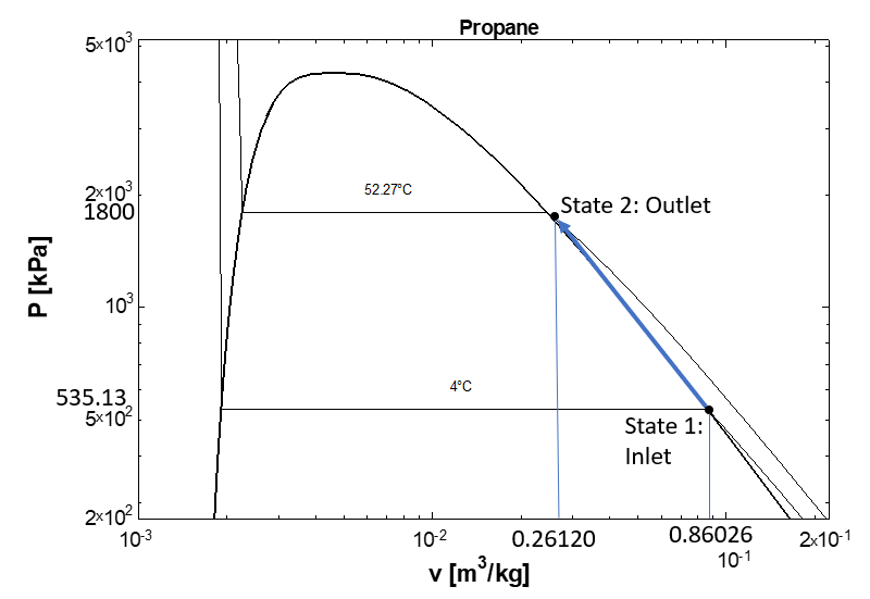
$$0.9\dot W_c = \dot m(h_1-h_2) \rightarrow \dot W_c = \dfrac{\dot m(h_1-h_2)}{0.9}$$Note that $\dot m$ is the mass flow of the propane from 16ii. Values for $h_1$ and $h_2$ are taken from the SLVM and superheated vapor tables, repectively. State 1 is a saturated vapor at 4°C and state 2 is superheated vapor at 18 bar and 60°C.
| State | T$[C]$ | P$[kPa]$ | X | h$[kJ/kg]$ | v$[m^3/kg]$ |
|---|---|---|---|---|---|
| 1 | 4.000 | 535.13 | 1 | 474.73 | 0.086026 |
| 2 | 60.000 | 1800 | NA | 537.95 | 0.026120 |
Finally,the COP for this cooling cycle is determined from the following definition.
$$COP_R=\dfrac{\dot Q_{cool}}{\mid \dot W_c \mid}$$where $\dot Q_{cool}$ is the cooling rate of $10 kW$ specified in problem 16ii ($\dot Q_p$).
m_dot_c = 0.0425         # mass flow entering the compressor [kg/s]
h_1 = 474.73             # rnthalpy of saturated vapor propane at 4°C [kJ/kg]
h_2 = 537.95             # enthalpy of superheated propane at 18 bar and 60°C [kJ/kg]

Q_dot_cool = 10                 # cycle cooling rate [kW\]
W_dot_c = m_dot_c*(h_1-h_2)/.9  # compressor power requirement [kW]
COP = Q_dot_cool/abs(W_dot_c)   # cycle COP

print('W_dot_c = ',round(W_dot_c,2),'kW')
print('COP = ',round(COP,3))