ME 200 – Thermodynamics I – Spring 2020
Homework 15: Open System Energy Balances
Part (i): Hair Dryer
Part (ii): Hoover Dam
Part (iii): Steam Power Plant
#Given Input:
V_1 = 1              # inlet air velocity [m/s]
V_dot_1 = 0.02832    # inlet air volumetric flow rate [m^3/s]
T_1 = 293.15         # inlet air temperature [K]
P_1 = 100            # inlet air pressure [kPa]
R = 8.314/28.97      # specific gas constant for air [kJ/kg-K]
Find:
Estimate the electrical power and comment on whether ignoring kinetic energy is reasonable
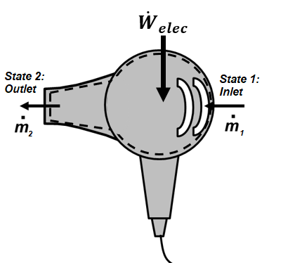
System Diagram:
The system chosen includes the air, electric resistance heater, and fan within the hair dryer.
Assumptions:
1) open system, 2) steady flow and steady state (SSSF), 3) no changes in potential energy, 4) negligible heat transfer for the system (adiabatic), 5) air treated as an ideal gas
Basic Equations:
$$\dfrac{dm}{dt}=\Sigma \dot m_{in}-\Sigma \dot m_{out}$$$$\dfrac{dE}{dt} = \dot Q- \dot W + \displaystyle\sum_{in} \dot m_{in} (h+ke+pe)_{in}-\displaystyle\sum_{out} \dot m_{out}(h+ke+pe)_{out}$$$$\dot m=\rho VA$$$$Pv=RT, dh=c_pdT$$Solution:
For the given nomenclature of this problem, conservation of mass and energy can be written for this single inlet, single outlet control volume as
$$\dfrac{dm}{dt} = \dot m_1 - \dot m_2$$$$\dfrac{dE}{dt} = \dot Q- \dot W_{elec} + \dot m_1(h+ke+pe)_1 - \dot m_2(h+ke+pe)_2$$For the assumptions of SSSF ($dm/dt=0, dE/dt=0$), adiabatic ($\dot Q=0$), and negligible changes in potential energy ($pe_2 = pe_1$), these can be rewritten as
$$\dot m_2 = \dot m_1 = \dot m$$ $$\dot W_{elec}=\dot m((h_1-h_2)+\dfrac{1}{2}(V_1^2-V_2^2))$$The mass flow rate can be determined from the inlet volumetric flow as
$$\dot m=\rho_1 A_1V_1=\dfrac{\dot V_1}{v_1}$$The specific volume of the air at the inlet can be determined from the ideal gas law as
$$v_1=RT_1/P_1$$such that $$\dot m = \dfrac{\dot V_1P_1}{RT_1}$$
The temperature change across the dryer is fairly significant and so we choose to use the ideal gas air tables to determine the enthalpy ($h = \int_{0}^{T_2}c_pdT$). Note that state 2 is state 2 from problem 14.i (T=60°C).
$$h_1(293.15K) = 293.25 kJ/kg$$$$h_2(333.15K) = 333.48k J/kg$$To evaluate whether it is important to consider kinetic energy changes for this problem, we evaluate the ratio of the change in kinetic energy to the change in enthalpy across the devices
$$\dfrac{\Delta ke}{\Delta h} = \dfrac{ke_2-ke_1}{h_2-h_1}$$V_2 = 15 # velocity of air leaving the hair dryer[m/s]
h_1 = 293.25 # specific enthalpy of air entering the hair dryer [kJ/kg]
h_2 = 333.48 # specific enthalpy of air leaving the hair dryer [kJ/kg]
ke_1 = 0.5*V_1**2/1000. # specific kinetic energy of air entering the hair dryer [kJ/kg]
ke_2 = 0.5*V_2**2/1000. # specific kinetic energy of air leaving the hair dryer [kJ/kg]
m_dot = V_dot_1*P_1/R/T_1 # mass flow rate of air through hair dryer [kg/s]
W_dot_elec = m_dot*((h_1-h_2)+(ke_1-ke_2)) # electrical power requirement for hair dryver [kW]
ke_ratio = (ke_2-ke_1)/(h_2-h_1) # ratio of kinetic energy to enthalpy differences across the dryer
print('W_dot_elec = ',round(W_dot_elec,2),'kW')
print('ke_ratio = ',round(ke_ratio,5))
At these conditions, the dryer consumes power at a rate of 1.35 kW. Neglecting kinetic enerygy differences in estimating this power is a very reasonable assumption since most of the electricity goes into raising the enthalpy (i.e., temperature) of the air.
#Given Input:
H = 220              # height of the Hoover Dam [m]
V_dot_1 = 850        # volumetric flow rate of water at inlet state [m^3/s]
P_1 = 100            # pressure at inlet state [kPa]
T_1 = 20             # temperature at inlet state [C]
Find:
a) minimum power requirement (MW),
b) pump outlet pressure if the pump is at the bottom of the dam.
System Diagram:
The water in the piping and pump are considered to be the system for part a. For part b, the system is chosen as the pump.


Assumptions:
1) open system, 2) steady state, steady flow (SSSF) 3) changes in kinetic energy are negligible 4) adiabatic (no heat transfer) 5) isothermal (no temperature changes) 6) water is assumed to be incompressible 7) changes in potential energy are negligible for the pump (part b)
Basic Equations:
$$\dfrac{dm}{dt}=\Sigma \dot m_{in}-\Sigma \dot m_{out}$$$$\dfrac{dE}{dt} = \dot Q- \dot W + \displaystyle\sum_{in} \dot m_{in} (h+ke+pe)_{in}-\displaystyle\sum_{out} \dot m_{out}(h+ke+pe)_{out}$$$$\dot m=\rho VA$$$$dh=du+vdP$$Solution:
Part a)
For the given nomenclature of this problem, conservation of mass and energy can be written for this single inlet, single outlet control volume as
$$\dfrac{dm}{dt} = \dot m_1 - \dot m_2$$$$\dfrac{dE}{dt} = \dot Q- \dot W_{pump} + \dot m_1(h+ke+pe)_1 - \dot m_2(h+ke+pe)_2$$For the assumptions of SSSF ($dm/dt=0, dE/dt=0$), adiabatic ($\dot Q=0$), and negligible changes in kinetic energy ($ke_2 = ke_1$), these can be rewritten as
$$\dot m_2 = \dot m_1 = \dot m$$ $$\dot W_{pump}=\dot m((h_1-h_2)+g(z_1-z_2))$$The mass flow rate can be determined from the inlet volumetric flow as
$$\dot m=\rho_1 A_1V_1=\dfrac{\dot V_1}{v_1}$$The specific volume of the water can be estimated as the saturated liquid specific volume at $T_1$ or
$$v_1 = v_f(20°C) = 0.0010018 m^3/kg$$The enthalpy change of an incompressible can be determined with
$$h_1-h_2 = (u_1-u_2) + v_1(P_1-P_2)$$Since internal energy of an incompressible only depends on temperature and $T_2=T_1$, then $u_2=u_1$. Also, $P_2=P_1$ so $h_2=h_1$ and
$$\dot W_{pump} = \dot mg(z_1-z_2)$$Note that $z_1-z_2 = -H$ so that
$$\dot W_{pump} = -\dot mgH$$v_1 = 0.0010018 # specific volume of water at 20°C [m^3/kg]
m_dot = V_dot_1/v_1 # mass flow rate of water [kg/s]
g = 9.81 # acceleration due to gravity (m/s^2)
W_dot_pump = -m_dot*g*H/1000 # pump power [kW]
print('W_dot_pump = ',round(W_dot_pump/1000,1),'MW')
Part b)
We can determine the pressure at the pump outlet using an energy balance on the pump under the same assumptions as considered in part a, except that the potential energy changes are negligible. Then, the energy balance reduces to
$$\dot W_{pump}=\dot m(h_1-h_{1a})$$where state $1a$ is at the exit of the pump. The enthalpy change of the incompressible water is
$$h_{1a}-h_1 = (u_{1a}-u_1) + v_1(P_{1a}-P_1)$$However $u_{1a}=u_1$ since $T_{1a}=T_1$ and the internal energy of an incompressible only depends on temperature. Then, the pressure exiting the pump can be determined as
$$P_{1a} = P_1 - \dfrac{\dot W_{pump}}{\dot V_1}$$P_1a = P_1 - W_dot_pump/V_dot_1 # pump exit pressure [kPa]
print('P_1a = ',round(P_1a,1),'kPa')
#Given Input:
T_1 = 50            # temperature of entering feedwater [C]
P_1 = 1000          # pressure of entering feedwater [kPa]
T_2 = 200           # temperature of entering superheated steam [C]
P_2 = 1000          # pressure of entering superheat steam [kPa]
P_3 = 1000          # pressure of exit stream [kPa]
x_3 = 0.0           # quality of exit stream
Find:
Determine the ratio of mass flow rates of the feedwater and superheated vapor.
Assumptions:
1) open system 2) steady state, steady flow (SSSF), 3) negligible effects of kinetic and potential energy, 4) adiabatric (no heat transfer), 5) no work device
Basic Equations:
$$\dfrac{dm}{dt}=\Sigma \dot m_{in}-\Sigma \dot m_{out}$$$$\dfrac{dE}{dt} = \dot Q- \dot W + \displaystyle\sum_{in} \dot m_{in} (h+ke+pe)_{in}-\displaystyle\sum_{out} \dot m_{out}(h+ke+pe)_{out}$$$$\dot m=\rho VA$$Solution:
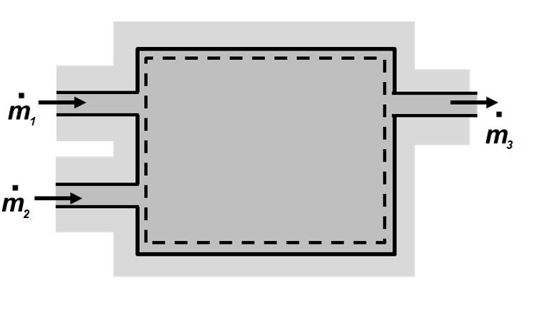
For the given nomenclature of this problem, conservation of mass and energy can be written for this dual inlet, single outlet control volume as
$$\dfrac{dm}{dt} = \dot m_{1} +\dot m_{2}-\dot m_{3}$$$$\dfrac{dE}{dt} = \dot Q- \dot W + \dot m_1(h+ke+pe)_1 + \dot m_2(h+ke+pe)_2 - \dot m_3(h+ke+pe)_3$$For the assumptions of SSSF ($dm/dt=0, dE/dt=0$), adiabatic ($\dot Q=0$), no work ($\dot W=0$) and negligible kinetic energy and potential energy terms, these can be rewritten as
$$\dot m_{3}=\dot m_{1} +\dot m_{2}$$$$\dot m_3 h_3 = \dot m_1 h_1 + \dot m_2 h_2$$These two equations can be combined to give the following
$$\dot m_1(h_1-h_3)=\dot m_2(h_3-h_2)$$Then, the ratio of feedwater to the superheated vapor flow rates must satisfy
$$\dfrac{\dot m_1}{\dot m_2}=\dfrac{h_3-h_2}{h_1-h_3}$$It is now just necessary to determine the enthalpies for the three states. State 1 is a compressed liquid 50°C and 10 bar and its enthalpy can be approximated as
$$h_1 = h_f(50°C)+v_f(50°C)(P_1-P_{sat}(50°C))$$State 2 is found in the superheated vapor table at 200°C and 10 bar, whereas state 3 is a saturated liquid at 50°C.
h_f_50C = 209.34       # saturated liquid enthalpy at 50°C [kJ/kg]
v_f_50C = 0.0010121    # saturated liquid specific volume at 50°C [m^3/kg]
P_sat_50C = 123.52     # saturation pressure at 50C [kPa]
h_2 = 2828.3           # superheated vapor enthalpy at 200°C and 10 bar [kJ/kg]
h_3 = 762.52           # saturated liquid enthalpy at 10 bar [kJ/kg]

h_1 = h_f_50C + v_f_50C*(P_1-P_sat_50C) # enthalpy of feedwater at (state 1) [kJ/kg]
m_dot_ratio = (h_3-h_2)/(h_1-h_3)       # ratio of feedwater to superheated vapor flow

print('h_1 = ',round(h_1),'kJ/kg')
print('m_dot_ratio = ',round(m_dot_ratio,3))