Weno-Hydro Buoyant Gallery
Lock Exchange problem.
The
lock-exchange system consists of fluids of different densities separated by a
sharp vertical interface. Small disturbances are amplified to form large scale
vortical motions which break down into random turbulent motions accompanied by
scalar mixing.
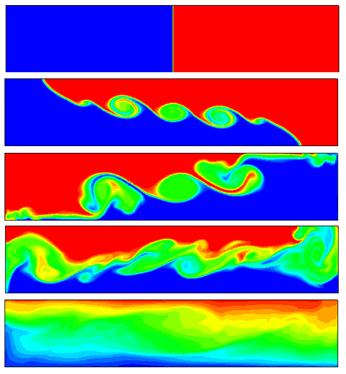
Figure 1.
Density contours at different time instances in a lock exchange system. Time
increases from top to bottom. Red denotes lighter and blue denotes denser
fluid.
Thermal instability
Denser
fluid overlies lighter fluid, separated by a horizontal interface. This
essentially unstable system forms finger-like structures as it undergoes
overturning and mixing
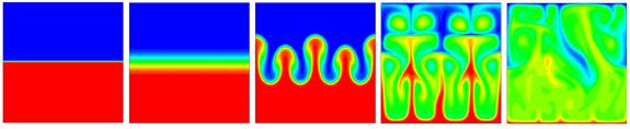
Figure 2.
Snapshots of density contours in a thermal instability
system. Time increases from left to right. Red denotes lighter fluid
while blue denotes denser fluid.
Steady buoyant jet
A
lighter fluid jet is injected horizontally into surroundings of heavier
density. The lighter jet rises vertically due to buoyancy as it moves across
the length of the domain. The figure below shows a non-buoyant jet adjacent to
a buoyant jet. The vertical displacement of the buoyant jet (right panel) is
apparent.
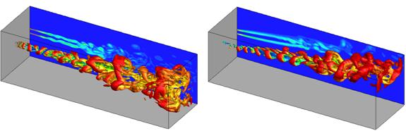
Figure 3.
Vorticity iso-surfaces with vorticity magnitude
projected on the transverse plane for a non-buoyant jet (left) and buoyant jet
(right).
Differentially heated cavity
A three-dimensional box
containing fluid is heated on one side and cooled on the other side. Fluid near
the heated wall becomes lighter and rises to the top, while fluid near the
cooled wall becomes denser and sinks to the bottom setting up convection
currents.

Figure 4.
Temperature iso-surfaces (left) and vorticity iso-surfaces (right) in a differentially heated cavity.
Starting buoyant jet
Lighter fluid is injected for
a short interval of time into an initially stationary surrounding. The fluid
rolls up into a starting head vortex, followed by a trailing stem. The figure
below shows snapshots at different instances of time as the lighter fluid
penetrates into the stationary fluid. The turbulent structures are dissipated
once injection into the domain ceases.
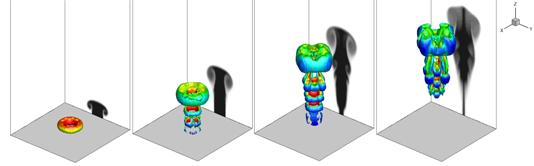
Figure 5.
Vorticity iso-surfaces with transported scalar contours
projected on the transverse plane for a starting buoyant jet. The four images
represent snapshots at four different time instances with time increasing from
left to right.